ESAB Inverter Arc Welder Model 130 GTS & S CC/TIG Manuel utilisateur
- Catégorie
- Système de soudage
- Taper
- Manuel utilisateur

INVERTER
ARC
WELDER
MODEL 130 GTS & S CC/TIG
• STICK
• TIG - HIGH FREQUENCY
- LIFT START
OPERATING MANUAL
July 1, 1997
TM
R
Manual No. 0-2620


GENERALMANUAL 0-2620
WARNING Read and understand this entire Operating Manual and your
employer’s safety practices before installing, operating, or servicing
the equipment.
WARNING While the information contained in this Operating Manual represents
our best judgement, Thermal Dynamics Corporation assumes no
liability for its use.
Thermal Arc Models 130 GTS & S CC/TIG Welder
Operating Manual Number 0-2620
Published by:
Thermal Dynamics Corporation
Industrial Park No. 2
West Lebanon, New Hampshire, USA 03784
(603) 298-5711
Copyright 1997 by
Thermal Dynamics Corporation
All rights reserved.
Reproduction of this work, in whole or in part, without written
permission of the publisher is prohibited.
The publisher does not assume and hereby disclaims any liability to
any party for any loss or damage caused by any error or omission in
this Operating Manual, whether such error results from negligence,
accident, or any other cause.
Printed in the United States of America
July 1, 1997

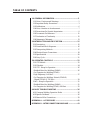
TABLE OF CONTENTS
1.0 GENERAL INFORMATION .....................................................2
1.01 Notes, Cautions and Warnings ................................................2
1.02 Important Safety Precautions ...................................................3
1.03 Publications .................................................................................6
1.04 Note, Attention et Avertissement ............................................7
1.05 Precautions De Securite Importantes ......................................8
1.06 Documents De Reference ........................................................ 11
1.07 Declaration of Conformity ......................................................12
1.08 Statement of Warranty .............................................................13
2.0 INTRODUCTION AND DESCRIPTION.................................15
2.01 Description ................................................................................15
2.02 Functional Block Diagrams.....................................................16
2.03 Transporting Methods .............................................................17
2.04 Electrical Input Connections...................................................18
2.05 Specifications.............................................................................20
2.06 Duty Cycle.................................................................................21
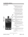
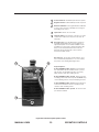
3.0 OPERATOR CONTROLS .....................................................22
3.01 GTS Models ...............................................................................22
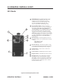
3.02 S Models.....................................................................................24
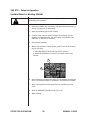
3.03 GTS – Setup for Operation......................................................26
Shielded Metal Arc Welding (SMAW) .........................................26
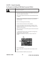
Gas Tungsten Arc Welding (GTAW)
High Frequency/Lift Start.............................................................27
Gas Tungsten Arc Welding -Pulsed (GTAW-P)
-Sloped (GTAW-S) -TIG Spot.........................................................29
3.04 S – Setup for Operation ...........................................................31
Shielded Metal Arc Welding (SMAW) .........................................31
Gas Tungsten Arc Welding (GTAW) Lift Start ...........................32
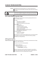
4.0 BASIC TROUBLESHOOTING ..............................................36
4.01 Common Welding Operation Faults .....................................36
4.02 Specific Problems......................................................................36
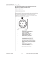
4.03 Remote 8-Pin Connections......................................................39
APPENDIX A – ACCESSORIES ................................................41
APPENDIX B – INTERCONNECTION DIAGRAMS ...................43

2
GENERAL MANUAL 0-2620
1.0 GENERAL INFORMATION
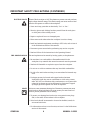
1.01 NOTES, CAUTIONS AND WARNINGS
Throughout this manual, notes, cautions, and warnings are used to
highlight important information. These highlights are categorized as
follows:
NOTE An operation, procedure, or background information which requires
additional emphasis or is helpful in efficient operation of the system.
CAUTION A procedure which, if not properly followed, may cause damage to the
equipment.
WARNING A procedure which, if not properly followed, may cause injury to the
operator or others in the operating area.

3
GENERALMANUAL 0-2620
WARNING
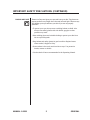
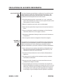
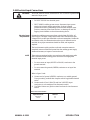
1.02 IMPORTANT SAFETY PRECAUTIONS
OPERATION AND MAINTENANCE OF PLASMA ARC EQUIPMENT
CAN BE DANGEROUS AND HAZARDOUS TO YOUR HEALTH.
To prevent possible injury, read, understand and follow all warnings, safety precautions and
instructions before using the equipment. Call 1-603-298-5711 or your local distributor if you have any
questions.
GASES AND FUMES Gases and fumes produced during the plasma cutting process can be
dangerous and hazardous to your health.
• Keep all fumes and gases from the breathing area. Keep your head out
of the welding fume plume.
• Use an air-supplied respirator if ventilation is not adequate to remove
all fumes and gases.
• The kinds of fumes and gases from the plasma arc depend on the kind
of metal being used, coatings on the metal, and the different
processes. You must be very careful when cutting or welding any
metals which may contain one or more of the following:
Antimony Chromium Mercury
Arsenic Cobalt Nickel
Barium Copper Selenium
Beryllium Lead Silver
Cadmium Manganese Vanadium
• Always read the Material Safety Data Sheets (MSDS) that should be
supplied with the material you are using. These MSDSs will give
you the information regarding the kind and amount of fumes and
gases that may be dangerous to your health.
• For information on how to test for fumes and gases in your
workplace, refer to item 1 in the Publications Section in this manual.
• Use special equipment, such as water or down draft cutting tables, to
capture fumes and gases.
• Do not use the plasma torch in an area where combustible or
explosive gases or materials are located.
• Phosgene, a toxic gas, is generated from the vapors of chlorinated
solvents and cleansers. Remove all sources of these vapors.

4
GENERAL MANUAL 0-2620
IMPORTANT SAFETY PRECAUTIONS (CONTINUED)
ELECTRIC SHOCK Electric Shock can injure or kill. The plasma arc process uses and produces
high voltage electrical energy. This electric energy can cause severe or fatal
shock to the operator or others in the workplace.
• Never touch any parts that are electrically “live” or “hot.”
• Wear dry gloves and clothing. Insulate yourself from the work piece
or other parts of the welding circuit.
• Repair or replace all worn or damaged parts.
• Extra care must be taken when the workplace is moist or damp.
• Install and maintain equipment according to NEC code, refer to item 4
in the Publications section of this manual.
• Disconnect power source before performing any service or repairs.
• Read and follow all the instructions in the Operating Manual.
FIRE AND EXPLOSION Fire and explosion can be caused by hot slag, sparks, or the plasma arc.
• Be sure there is no combustible or flammable material in the
workplace. Any material that cannot be removed must be protected.
• Ventilate all flammable or explosive vapors from the workplace.
• Do not cut or weld on containers that may have held combustibles.
• Provide a fire watch when working in an area where fire hazards may
exist.
• Hydrogen gas may be formed and trapped under aluminum
workpieces when they are cut underwater or while using a water
table. DO NOT cut aluminum alloys underwater or on a water table
unless the hydrogen gas can be eliminated or dissipated. Trapped
hydrogen gas that is ignited will cause an explosion.
NOISE Noise can cause permanent hearing loss. Plasma arc processes can cause
noise levels to exceed safe limits. You must protect your ears from loud
noise to prevent permanent loss of hearing.
• To protect your hearing from loud noise, wear protective ear plugs
and/or ear muffs. Protect others in the workplace.
• Noise levels should be measured to be sure the decibels (sound) do
not exceed safe levels.
• For information on how to test for noise, see item 1 in the Publications
section of this manual.

5
GENERALMANUAL 0-2620
IMPORTANT SAFETY PRECAUTIONS (CONTINUED)
PLASMA ARC RAYS Plasma Arc Rays can injure your eyes and burn your skin. The plasma arc
process produces very bright ultra violet and infra red light. These arc rays
will damage your eyes and burn your skin if you are not properly
protected.
• To protect your eyes, always wear a welding helmet or shield. Also
always wear safety glasses with side shields, goggles or other
protective eye wear.
• Wear welding gloves and suitable clothing to protect your skin from
the arc rays and sparks.
• Keep helmet and safety glasses in good condition. Replace lenses
when cracked, chipped or dirty.
• Protect others in the work area from the arc rays. Use protective
booths, screens or shields.
• Use the shade of lens as recommended in the Operating Manual.

6GENERAL
MANUAL 0-2620
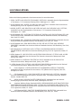
1.03 PUBLICATIONS
Refer to the following standards or their latest revisions for more information:
1. OSHA, SAFETY AND HEALTH STANDARDS, 29CFR 1910, obtainable from the Superintendent
of Documents, U.S. Government Printing Office, Washington, D.C. 20402
2. ANSI Standard Z49.1, SAFETY IN WELDING AND CUTTING, obtainable from the American
Welding Society, 550 N.W. LeJeune Rd, Miami, FL 33126
3. NIOSH, SAFETY AND HEALTH IN ARC WELDING AND GAS WELDING AND CUTTING,
obtainable from the Superintendent of Documents, U.S. Government Printing Office,
Washington, D.C. 20402
4. ANSI Standard Z87.1, SAFE PRACTICES FOR OCCUPATION AND EDUCATIONAL EYE AND
FACE PROTECTION, obtainable from American National Standards Institute, 1430 Broadway,
New York, NY 10018
5. ANSI Standard Z41.1, STANDARD FOR MEN’S SAFETY-TOE FOOTWEAR, obtainable from the
American National Standards Institute, 1430 Broadway, New York, NY 10018
6. ANSI Standard Z49.2, FIRE PREVENTION IN THE USE OF CUTTING AND WELDING
PROCESSES, obtainable from American National Standards Institute, 1430 Broadway, New York,
NY 10018
7. AWS Standard A6.0, WELDING AND CUTTING CONTAINERS WHICH HAVE HELD
COMBUSTIBLES, obtainable from American Welding Society, 550 N.W. LeJeune Rd, Miami, FL
33126
8. NFPA Standard 51, OXYGEN-FUEL GAS SYSTEMS FOR WELDING, CUTTING AND ALLIED
PROCESSES, obtainable from the National Fire Protection Association, Batterymarch Park,
Quincy, MA 02269
9. NFPA Standard 70, NATIONAL ELECTRICAL CODE, obtainable from the National Fire
Protection Association, Batterymarch Park, Quincy, MA 02269
10. NFPA Standard 51B, CUTTING AND WELDING PROCESSES, obtainable from the National
Fire Protection Association, Batterymarch Park, Quincy, MA 02269
11. CGA Pamphlet P-1, SAFE HANDLING OF COMPRESSED GASES IN CYLINDERS,
obtainable from the Compressed Gas Association, 1235 Jefferson Davis Highway, Suite 501,
Arlington, VA 22202
12. CSA Standard W117.2, CODE FOR SAFETY IN WELDING AND CUTTING, obtainable
from the Canadian Standards Association, Standards Sales, 178 Rexdale Boulevard, Rexdale,
Ontario, Canada M9W 1R3
13. NWSA booklet, WELDING SAFETY BIBLIOGRAPHY obtainable from the National
Welding Supply Association, 1900 Arch Street, Philadelphia, PA 19103
14. American Welding Society Standard AWSF4.1, RECOMMENDED SAFE PRACTICES FOR
THE PREPARATION FOR WELDING AND CUTTING OF CONTAINERS AND PIPING THAT
HAVE HELD HAZARDOUS SUBSTANCES, obtainable from the American Welding Society, 550
N.W. LeJeune Rd, Miami, FL 33126
15. ANSI Standard Z88.2, PRACTICE FOR RESPIRATORY PROTECTION, obtainable from
American National Standards Institute, 1430 Broadway, New York, NY 10018

7
GENERALMANUAL 0-2620
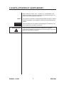
1.04 NOTE, ATTENTION ET AVERTISSEMENT
Dans ce manuel, les mots “note,” “attention,” et “avertissement” sont
utilisés pour mettre en relief des informations à caractère important. Ces
mises en relief sont classifiées comme suit :
NOTET oute opération, procédure ou renseignement général sur lequel il importe
d’insister davantage ou qui contribue à l’efficacité de fonctionnement du
système.
ATTENTION Toute procédure pouvant résulter l’endommagement du matériel en cas
de non-respect de la procédure en question.
AVERTISSEMENT Toute procédure pouvant provoquer des blessures de l’opérateur
ou des autres personnes se trouvant dans la zone de travail en cas de non-
respect de la procédure en question.

8
GENERAL MANUAL 0-2620
AVERTISSEMENT
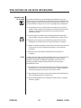
1.05 PRECAUTIONS DE SECURITE IMPORTANTES
L’OPÉRATION ET LA MAINTENANCE DU MATÉRIEL DE SOUDAGE
À L’ARC AU JET DE PLASMA PEUVENT PRÉSENTER
DES RISQUES ET DES DANGERS DE SANTÉ.
Il faut communiquer aux opérateurs et au personnel TOUS les dangers possibles. Afin d’éviter les
blessures possibles, lisez, comprenez et suivez tous les avertissements, toutes les précautions de
sécurité et toutes les consignes avant d’utiliser le matériel. Composez le + 603-298-5711 ou votre
distributeur local si vous avez des questions.
FUMÉE et GAZ La fumée et les gaz produits par le procédé de jet de plasma peuvent
présenter des risques et des dangers de santé.
• Eloignez toute fumée et gaz de votre zone de respiration. Gardez
votre tête hors de la plume de fumée provenant du chalumeau.
• Utilisez un appareil respiratoire à alimentation en air si l’aération
fournie ne permet pas d’éliminer la fumée et les gaz.
• Les sortes de gaz et de fumée provenant de l’arc de plasma dépendent
du genre de métal utilisé, des revêtements se trouvant sur le métal
et des différents procédés. Vous devez prendre soin lorsque vous
coupez ou soudez tout métal pouvant contenir un ou plusieurs des
éléments suivants:
antimoine cadmium mercure
argent chrome nickel
arsenic cobalt plomb
baryum cuivre sélénium
béryllium manganèse vanadium
• Lisez toujours les fiches de données sur la sécurité des matières (sigle
américain “MSDS”); celles-ci devraient être fournies avec le matériel
que vous utilisez. Les MSDS contiennent des renseignements quant
à la quantité et la nature de la fumée et des gaz pouvant poser des
dangers de santé.
• Pour des informations sur la manière de tester la fumée et les gaz de
votre lieu de travail, consultez lparticle 1 et les documents cités à la
page 11.
• Utilisez un équipement spécial tel que des tables de coupe à débit
d’eau ou à courant descendant pour capter la fumée et les gaz.
• N’utilisez pas le chalumeau au jet de plasma dans une zone où se
trouvent des matières ou des gaz combustibles ou explosifs.
• Le phosgène, un gaz toxique, est généré par la fumée provenant des
solvants et des produits de nettoyage chlorés. Eliminez toute source
de telle fumée.

9
GENERALMANUAL 0-2620
PRECAUTIONS DE SECURITE IMPORTANTES
CHOC ELECTRIQUE Les chocs électriques peuvent blesser ou même tuer. Le procédé au jet de
plasma requiert et produit de l’énergie électrique haute tension. Cette
énergie électrique peut produire des chocs graves, voire mortels, pour
l’opérateur et les autres personnes sur le lieu de travail.
• Ne touchez jamais une pièce “sous tension” ou “vive”; portez des
gants et des vêtements secs. Isolez-vous de la pièce de travail ou des
autres parties du circuit de soudage.
• Réparez ou remplacez toute pièce usée ou endommagée.
• Prenez des soins particuliers lorsque la zone de travail est humide ou
moite.
• Montez et maintenez le matériel conformément au Code électrique
national des Etats-Unis. (Voir la page 6, article 9.)
• Débranchez l’alimentation électrique avant tout travail d’entretien ou
de réparation.
• Lisez et respectez toutes les consignes du Manuel de consignes.
INCENDIE ET
EXPLOSION Les incendies et les explosions peuvent résulter des scories chaudes, des
étincelles ou de l’arc de plasma. Le procédé à l’arc de plasma produit du
métal, des étincelles, des scories chaudes pouvant mettre le feu aux
matières combustibles ou provoquer l’explosion de fumées inflammables.
• Soyez certain qu’aucune matière combustible ou inflammable ne se
trouve sur le lieu de travail. Protégez toute telle matière qu’il est
impossible de retirer de la zone de travail.
• Procurez une bonne aération de toutes les fumées inflammables ou
explosives.
• Ne coupez pas et ne soudez pas les conteneurs ayant pu renfermer
des matières combustibles.
• Prévoyez une veille d’incendie lors de tout travail dans une zone
présentant des dangers d’incendie.
• Le gas hydrogène peut se former ou s’accumuler sous les pièces de
travail en aluminium lors’quelles sont coupeés sous l’eau ou sur une
table d’eau. NE PAS couper les alliages en aluminium sous l’eau ou
sur une table d’eau à mains que le gas hydrogène peut s’échapper
ou se dissiper. Le gas hydrogène accumulé explosera si enflammé.

10
GENERAL MANUAL 0-2620
PRECAUTIONS DE SECURITE IMPORTANTES
RAYONS D’ARC
DE PLASMA Les rayons provenant de l’arc de plasma peuvent blesser vos yeux et
brûler votre peau. Le procédé à l’arc de plasma produit une lumière infra-
rouge et des rayons ultra-violets très forts. Ces rayons d’arc nuiront à vos
yeux et brûleront votre peau si vous ne vous protégez pas correctement.
• Pour protéger vos yeux, portez toujours un casque ou un écran de
soudeur. Portez toujours des lunettes de sécurité munies de parois
latérales ou des lunettes de protection ou une autre sorte de
protection oculaire.
• Portez des gants de soudeur et un vêtement protecteur approprié
pour protéger votre peau contre les étincelles et les rayons de l’arc.
• Maintenez votre casque et vos lunettes de protection en bon état.
Remplacez toute lentille sale ou comportant fissure ou rognure.
• Protégez les autres personnes se trouvant sur la zone de travail contre
les rayons de l’arc en fournissant des cabines ou des écrans de
protection.
• Respectez le teint de lentille recommandé dans le manuel de
consignes.
BRUIT Le bruit peut provoquer une perte permanente de l’ouïe. Les procédés de
soudage à l’arc de plasma peuvent provoquer des niveaux sonores
supérieurs aux limites normalement acceptables. Vous dúvez vous
protéger les oreilles contre les bruits forts afin d’éviter une perte
permanente de l’ouïe.
• Pour protéger votre ouïe contre les bruits forts, portez des tampons
protecteurs et/ou des protections auriculaires. Protégez également
les autres personnes se trouvant sur le lieu de travail.
• Il faut mesurer les niveaux sonores afin d’assurer que les décibels (le
bruit) ne dépassent pas les niveaux sûrs.
• Pour des renseignements sur la manière de tester le bruit, consultez
l’article 1, page 11.

11 GENERAL
MANUAL 0-2620
1.06 DOCUMENTS DE REFERENCE
Consultez les normes suivantes ou les révisions les plus récentes ayant été faites à celles-ci pour de plus
amples renseignements :
1. OSHA, NORMES DE SÉCURITÉ DU TRAVAIL ET DE PROTECTION DE LA SANTÉ, 29CFR
1910, disponible auprès du Superintendent of Documents, U.S. Government Printing Office,
Washington, D.C. 20402
2. Norme ANSI Z49.1, LA SÉCURITÉ DES OPÉRATIONS DE COUPE ET DE SOUDAGE,
disponible auprès de la Société Américaine de Soudage (American Welding Society), 550 N.W.
LeJeune Rd., Miami, FL 33126
3. NIOSH, LA SÉCURITÉ ET LA SANTÉ LORS DES OPÉRATIONS DE COUPE ET DE SOUDAGE
À L’ARC ET AU GAZ, disponible auprès du Superintendent of Documents, U.S. Government
Printing Office, Washington, D.C. 20402
4. Norme ANSI Z87.1, PRATIQUES SURES POUR LA PROTECTION DES YEUX ET DU VISAGE
AU TRAVAIL ET DANS LES ECOLES, disponible de l’Institut Américain des Normes Nationales
(American National Standards Institute), 1430 Broadway, New York, NY 10018
5. Norme ANSI Z41.1, NORMES POUR LES CHAUSSURES PROTECTRICES, disponible auprès de
l’American National Standards Institute, 1430 Broadway, New York, NY 10018
6. Norme ANSI Z49.2, PRÉVENTION DES INCENDIES LORS DE L’EMPLOI DE PROCÉDÉS DE
COUPE ET DE SOUDAGE, disponible auprès de l’American National Standards Institute, 1430
Broadway, New York, NY 10018
7. Norme A6.0 de l’Association Américaine du Soudage (AWS), LE SOUDAGE ET LA COUPE DE
CONTENEURS AYANT RENFERMÉ DES PRODUITS COMBUSTIBLES, disponible auprès de la
American Welding Society, 550 N.W. LeJeune Rd., Miami, FL 33126
8. Norme 51 de l’Association Américaine pour la Protection contre les Incendies (NFPA), LES
SYSTEMES À GAZ AVEC ALIMENTATION EN OXYGENE POUR LE SOUDAGE, LA COUPE
ET LES PROCÉDÉS ASSOCIÉS, disponible auprès de la National Fire Protection Association,
Batterymarch Park, Quincy, MA 02269
9. Norme 70 de la NFPA, CODE ELECTRIQUE NATIONAL, disponible auprès de la National Fire
Protection Association, Batterymarch Park, Quincy, MA 02269
10. Norme 51B de la NFPA, LES PROCÉDÉS DE COUPE ET DE SOUDAGE, disponible auprès
de la National Fire Protection Association, Batterymarch Park, Quincy, MA 02269
11. Brochure GCA P-1, LA MANIPULATION SANS RISQUE DES GAZ COMPRIMÉS EN
CYLINDRES, disponible auprès de l’Association des Gaz Comprimés (Compressed Gas
Association), 1235 Jefferson Davis Highway, Suite 501, Arlington, VA 22202
12. Norme CSA W117.2, CODE DE SÉCURITÉ POUR LE SOUDAGE ET LA COUPE,
disponible auprès de l’Association des Normes Canadiennes, Standards Sales, 178 Rexdale
Boulevard, Rexdale, Ontario, Canada, M9W 1R3
13. ivret NWSA, BIBLIOGRAPHIE SUR LA SÉCURITÉ DU SOUDAGE, disponible auprès de
l’Association Nationale de Fournitures de Soudage (National Welding Supply Association), 1900
Arch Street, Philadelphia, PA 19103
14. Norme AWSF4.1 de l’Association Américaine de Soudage, RECOMMANDATIONS DE
PRATIQUES SURES POUR LA PRÉPARATION À LA COUPE ET AU SOUDAGE DE
CONTENEURS ET TUYAUX AYANT RENFERMÉ DES PRODUITS DANGEREUX , disponible
auprès de la American Welding Society, 550 N.W. LeJeune Rd., Miami, FL 33126
15. Norme ANSI Z88.2, PRATIQUES DE PROTECTION RESPIRATOIRE, disponible auprès de
l’American National Standards Institute, 1430 Broadway, New York, NY 10018

12GENERAL
MANUAL 0-2620
1.07 DECLARATION OF CONFORMITY
Manufacturer: Thermal Dynamics Corporation
Address: Industrial Park #2
West Lebanon, New Hampshire 03784
USA
The equipment described in this manual conforms to all applicable aspects and regulations of the ‘Low
Voltage Directive’ (European Council Directive 73/23/EU, as recently changed in Directive 93/63/EU)
and to the National legislation for the enforcement of this Directive.
The equipment described in this manual conforms to all applicable aspects and regulations of the “EMC
Directive” (European Council Directive 89/336/EEC) and to the National legislation for the
enforcement of this Directive.
Serial numbers are unique with each individual piece of equipment and details description, parts used
to manufacture a unit and date of manufacture.
National Standard and Technical Specifications
The product is designed and manufactured to a number of standards and technical requirements
among them are:
* CSA (Canadian Standards Association) standard C22.2 number 60-M1990 for Arc welding equipment.
* UL (Underwriters Laboratory) rating 94VO flammability testing for all printed-circuit boards used.
* CENELEC EN50199 EMC Product Standard for Arc Welding Equipment March 1995.
* IEC 974-1 (BS 638-PT10) (EN 60 974-1) applicable to welding equipment and associated accessories.
* Extensive product design verification is conducted at the manufacturing facility as part of the routine
design and manufacturing process, to ensure the product is safe and performs as specified. Rigorous
testing is incorporated into the manufacturing process to ensure the manufactured product meets or
exceeds all design specifications.
Thermal Dynamics has been manufacturing products that perform in a safe manner for more than 30
years and will continue to achieve excellence in our area of manufacture.
Manufacturers responsible representative: David Ashworth
Vice President & Managing Director
Thermadyne Europe
Chorley England.

13 GENERAL
MANUAL 0-2620
1.08 STATEMENT OF WARRANTY
LIMITED WARRANTY: Thermal Dynamics Corporation (hereinafter “Thermal”) warrants that its
products will be free of defects in workmanship or material. Should any failure to conform to this
warranty appear within the time period applicable to the Thermal products as stated below, Thermal
shall, upon notification thereof and substantiation that the product has been stored, installed, operated,
and maintained in accordance with Thermal’s specifications, instructions, recommen dations and
recognized standard industry practice, and not subject to misuse, repair, neglect, alteration, or accident,
correct such defects by suitable repair or replacement, at Thermal’s sole option, of any components or
parts of the product determined by Thermal to be defective.
THIS WARRANTY IS EXCLUSIVE AND IS IN LIEU OF ANY WARRANTY OF MERCHANTABILITY
OR FITNESS FOR A PARTICULAR PURPOSE.
LIMITATION OF LIABILITY: Thermal shall not under any circumstances be liable for special or
consequential damages, such as, but not limited to, damage or loss of purchased or replacement goods,
or claims of customers of distributor (hereinafter “Purchaser”) for service interruption. The remedies of
the Purchaser set forth herein are exclusive and the liability of Thermal with respect to any contract, or
anything done in connection therewith such as the performance or breach thereof, or from the
manufacture, sale, delivery, resale, or use of any goods covered by or furnished by Thermal whether
arising out of contract, negligence, strict tort, or under any warranty, or otherwise, shall not, except as
expressly provided herein, exceed the price of the goods upon which such liability is based.
THIS WARRANTY BECOMES INVALID IF REPLACEMENT PARTS OR ACCESSORIES ARE USED
WHICH MAY IMPAIR THE SAFETY OR PERFORMANCE OF ANY THERMAL PRODUCT.
THIS WARRANTY IS INVALID IF THE PRODUCT IS SOLD BY NON-AUTHORIZED PERSONS.
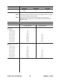
The limited warranty periods for Thermal products shall be as follows: A maximum of three (3) years
from date of sale to an authorized distributor and a maximum of two (2) years from date of sale by such
distributor to the Purchaser, and with the following further limitations on such two (2) year period:
PAK UNITS, POWER SUPPLIES PARTS LABOR
MAIN POWER MAGNETICS ....................................... 2 YEARS ..................1 YEAR
ORIGINAL MAIN POWER RECTIFIER ...................... 2 YEARS ..................1 YEAR
CONTROL PC BOARD .................................................. 2 YEARS ..................1 YEAR
ALL OTHER CIRCUITS AND COMPONENTS .......... 1 YEAR ...................1 YEAR
INCLUDING, BUT NOT LIMITED TO, STARTING
CIRCUIT, CONTACTORS, RELAYS, SOLENOIDS,
PUMPS, POWER SWITCHING SEMI-CONDUCTORS
CONSOLES, CONTROL EQUIPMENT, HEAT...................... 1 YEAR ...................1 YEAR
EXCHANGES, AND ACCESSORY EQUIPMENT
TORCH AND LEADS............................................................ 180 DAYS................180 DAYS
REPAIR/REPLACEMENT PARTS ......................................... 90 DAYS..................90 DAYS
Warranty repairs or replacement claims under this limited warranty must be submitted by an
authorized Thermal Arc
®
repair facility within thirty (30) days of the repair. Authorized Thermal Arc
®
repair facilities are authorized distributors and authorized Thermal Arc
®
Service Centers. No
transportation costs of any kind will be paid under this warranty. Transportation charges to send
products to an authorized warranty repair facility shall be the responsibility of the customer. All
returned goods shall be at the customer’s risk and expense. This warranty supersedes all previous
Thermal warranties.
Thermal Arc
®
is a Registered Trademark of Thermal Dynamics.
Effective January 18, 1991

MANUAL 0-2620 14 INTRODUCTION
2.0 INTRODUCTION AND DESCRIPTION
2.01 Description
The Thermal Arc
™
Model 130 GTS and S are single-phase DC arc welding
power sources with Constant Current (CC) output characteristics. Each
GTS unit is equipped with a built-in Sloper, Pulser, gas control solenoid,
Lift Start TIG, and a High-Frequency arc starter for use with Gas Tungsten
Arc Welding (GTAW). All units are designed for use with Shielded Metal
Arc Welding (SMAW) and Gas Tungsten Arc Welding-Lift Start processes.
19
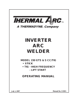
1305
AMPS
VOLTS
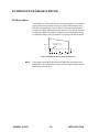
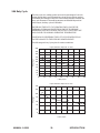
Arc Characteristics
"CURRENT" Control
Figure 1. Model 130 GTS and S CC/TIG Volt-Ampere curves
NOTE Volt-Ampere curves show the maximum Voltage and Amperage output
capabilities of the welding power source. Curves of other settings will fall
between the curves shown.

MANUAL 0-2620 15 INTRODUCTION
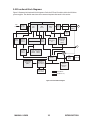
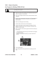
2.02 Functional Block Diagrams
Figure 2 illustrates the functional block diagram of both the GTS and S models within the 100 Series
power supplies. The shaded areas show the common subsystems discussed in this section.
Main
Circuit
Breaker
Input
Diode
IGBT
Inverter
Output
Diode
Thermal Detector Power Module (IPM)
Input
Power
Output
Inductor
Coupling
High
Frequency
Unit
Lift Tig Mode
Output Short
Sensing
Circuit
Output
Transformer
(TI)
Coil
Current
Transformer
(CT-1)
Capacitor
Sequence
Control
Current
Adjustment
Circuit
Reference
Adjustments &
Control Switches
Torch Control
Connection
(CON1)
Logic Circuit
Board (PCB4)
Thermal
Sensor
Circuit
Trouble
Sensor
Circuit
To each control circuit
+12VDC +20VDC
+24VDC +10VDC
Voltage
Sensor
Drive
Circuit
(PCB2)
DC Power
Gas
Control
Circuit
+
+
–
–
Solenoid
GTS/S Models
GTS Models only
+
Figure 2. Functional block diagram

MANUAL 0-2620 16 INTRODUCTION
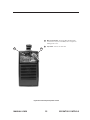
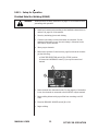
2.03 Transporting Methods
These units are equipped with one handle and a shoulder strap for
carrying purposes.
WARNING ELECTRIC SHOCK can kill.
• DO NOT TOUCH live electrical parts.
• Disconnect input power conductors from de-energized supply line
before moving welding power source.
WARNING FALLING EQUIPMENT can cause serious personal injury and equipment
damage.
• Lift unit with handle or shoulder strap on top of case.
• Use hand cart or similar device of adequate capacity.
• If using a fork lift vehicle, place and secure unit on a proper skid
before transporting.
• This unit has a built-in handle and shoulder strap on top of case for
lifting. Be sure unit is lifted and transported safely and securely.

MANUAL 0-2620 17 INTRODUCTION
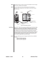
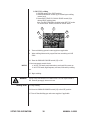
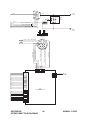
2.04 Electrical Input Connections
WARNING ELECTRIC SHOCK can kill; SIGNIFICANT DC VOLTAGE is present after
removal of input power.
• DO NOT TOUCH live electrical parts.
• SHUT DOWN welding power source, disconnect input power
employing lockout/tagging procedures. Lockout/tagging
procedures consist of padlocking line disconnect switch in open
position, removing fuses from fuse box, or shutting off and red-
tagging circuit breaker or other disconnecting device.
Electrical Input Operate the welding power source from a single-phase 50/60 Hz, AC
Requirements power supply. The input voltage must match one of the electrical input
voltages shown on the input data label on the unit nameplate. Contact the
local electric utility for information about the type of electrical service
available, how proper connections should be made, and inspection
required.
The line disconnect switch provides a safe and convenient means to
completely remove all electrical power from the welding power supply
whenever necessary to inspect or service the unit.
NOTE These units are equipped with a two-conductor with earth power cable
that is connected at the welding power source end for single-phase
electrical input power.
• Do not connect an input (WHITE or BLACK) conductor to the
ground terminal.
• Do not connect the ground (GREEN) conductor to an input line
terminal.
Refer to figure 3 and:
1) Connect end of ground (GREEN) conductor to a suitable ground.
Use a grounding method that complies with all applicable electrical
codes.
2) Connect ends of line 1 (BLACK) and line 2 (WHITE) input
conductors to a de-energized line disconnect switch.
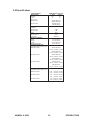
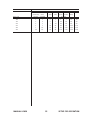
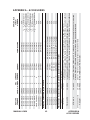
3) Use Table 1 below as a guide to select line fuses for the disconnect
switch.
Table 1. Fuse Size Selection
Input Power/Input Voltage Fuse Size (Amperes)
Single-Phase Model 130GTS/S
208-230 VAC 30
115 VAC 25
La page est en cours de chargement...
La page est en cours de chargement...
La page est en cours de chargement...
La page est en cours de chargement...
La page est en cours de chargement...
La page est en cours de chargement...
La page est en cours de chargement...
La page est en cours de chargement...
La page est en cours de chargement...
La page est en cours de chargement...
La page est en cours de chargement...
La page est en cours de chargement...
La page est en cours de chargement...
La page est en cours de chargement...
La page est en cours de chargement...
La page est en cours de chargement...
La page est en cours de chargement...
La page est en cours de chargement...
La page est en cours de chargement...
La page est en cours de chargement...
La page est en cours de chargement...
La page est en cours de chargement...
La page est en cours de chargement...
La page est en cours de chargement...
La page est en cours de chargement...
La page est en cours de chargement...
La page est en cours de chargement...
La page est en cours de chargement...
La page est en cours de chargement...
La page est en cours de chargement...
-
 1
1
-
 2
2
-
 3
3
-
 4
4
-
 5
5
-
 6
6
-
 7
7
-
 8
8
-
 9
9
-
 10
10
-
 11
11
-
 12
12
-
 13
13
-
 14
14
-
 15
15
-
 16
16
-
 17
17
-
 18
18
-
 19
19
-
 20
20
-
 21
21
-
 22
22
-
 23
23
-
 24
24
-
 25
25
-
 26
26
-
 27
27
-
 28
28
-
 29
29
-
 30
30
-
 31
31
-
 32
32
-
 33
33
-
 34
34
-
 35
35
-
 36
36
-
 37
37
-
 38
38
-
 39
39
-
 40
40
-
 41
41
-
 42
42
-
 43
43
-
 44
44
-
 45
45
-
 46
46
-
 47
47
-
 48
48
-
 49
49
-
 50
50


ESAB Inverter Arc Welder Model 130 GTS & S CC/TIG Manuel utilisateur
- Catégorie
- Système de soudage
- Taper
- Manuel utilisateur
dans d''autres langues
Documents connexes
-
 Firepower Plasma Cutting Power Supply Firepower™ PC-800 Manuel utilisateur
-
 Firepower Plasma Cutting Power Supply Firepower PC-500 Manuel utilisateur
-
 Thermal Arc Inverter Arc Welder Model LT300 CC/Tig Manuel utilisateur
-
 Thermal Arc Inverter Arc Welder Model 400GMS CC/CV Manuel utilisateur
-
 Thermal Dynamics Plasma Welding Torch Model PWH/M-2A Manuel utilisateur
-
 Thermal Arc Inverter Arc Welder Model PS-3000 Manuel utilisateur
-
 Thermal Dynamics 38 CUTMASTER™ Plasma Cutting System Manuel utilisateur
-
ESAB DRAG-GUN™ Plasma Cutter with Built-In Air Manuel utilisateur
-
 Thermal Arc Inverter Arc Welder Model 150 GTS & S CC/TIG Manuel utilisateur
-
 Firepower Plasma Cutting Power Supply Manuel utilisateur


