Dell PowerEdge C6320 Guide de démarrage rapide
- Taper
- Guide de démarrage rapide

Dell PowerEdge C6320
Getting Started Guide
Příručka Začínáme
Guide de mise en route
Handbuch zum Einstieg
Οδηγός «Τα πρώτα βήματα»
Instrukcja uruchomienia
Руководство по началу работы
Priručnik za početak rada
Guía de introducción
Başlangıç Kılavuzu
הדובע תליחת ךירדמ
Scan to see how-to videos, documentation,
andtroubleshooting information


Dell PowerEdge C6320
Getting Started Guide

NOTE: A NOTE indicates important information that helps you make better use
of your computer.
CAUTION: A CAUTION indicates either potential damage to hardware or loss
of data and tells you how to avoid the problem.
WARNING: A WARNING indicates a potential for property damage, personal
injury, or death.
Dell End User License Agreement
Before using your system, read the Dell Software License Agreement that shipped with your
system. If you do not accept the terms of agreement, see Dell.com/contactdell.
Save all software media that shipped with your system. These media are backup copies of the
software installed on your system.
Copyright © 2016 Dell Inc. All rights reserved. This product is protected by U.S. and
international copyright and intellectual property laws. Dell
™
and the Dell logo are trademarks of
Dell Inc. in the United States and/or other jurisdictions. All other marks and names mentioned
herein may be trademarks of their respective companies.
2016 – 01
P/N CFK9F Rev. A01

Installation and configuration │ 5
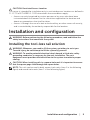
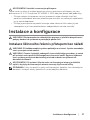
CAUTION: Restricted Access Location
This server is intended for installation only in restricted access locations as defined in
Cl. 1.2.7.3 of IEC 60950-1: 2001 where both these conditions apply:
• Access can only be gained by service persons or by users who have been
instructed about the reasons for the restrictions applied to the location and
about any precautions that shall be taken.
• Access is through the use of a tool or lock and key, or other means of security,
and is controlled by the authority responsible for the location.
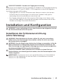
Installation and configuration
WARNING: Before performing the following procedure, read and follow the
safety instructions that came with the system.
Installing the tool-less rail solution
WARNING: Whenever you need to lift the system, get others to assist you.
To avoid injury, do not attempt to lift the system by yourself.
WARNING: To avoid a potential electrical shock hazard, a third wire safety
grounding conductor is necessary for the rack installation. The rack
equipment must provide sufficient airflow to the system to maintain proper
cooling.
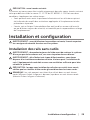
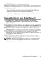
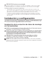
CAUTION: When installing rails in a square-hole rack it is important to ensure
that the square pegs slide through the square holes.
NOTE: The rails can be used in both square-hole racks (item 1 in the following
figure) and round-hole racks (item 2 in the following figure).

6 │ Installation and configuration
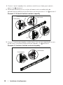
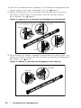
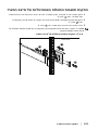
1. To open the rail latches, push the latch release buttons on the midpoints of the
end pieces of the rails. See
1
in figure 1.
2. Align the end pieces of the rails on the vertical rack flanges to seat the pegs in
the bottom and top holes of the desired U spaces. See
2
in figure 1.
Figure 1: Pushing the latch release buttons
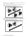
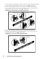
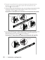
3. To lock the latches in place, engage the end of the rails until they seat on the
vertical rack flanges, and release the latch release buttons. See
3
in Figure 2.
Figure 2: Releasing the latch release buttons
1
2
1
1
2
2
Back View
Latch Release Button
Front View
3
3
Back View
Front View

Installation and configuration │ 7
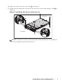
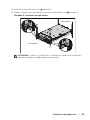
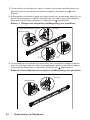
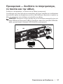
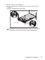
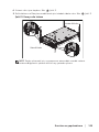
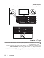
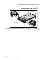
4. Slide the system into the rack. See
4
in Figure 3.
5. Tighten the thumbscrews to secure the rack ears to the rack flanges. See
5
in
Figure 3.
Figure 3: Installing the chassis onto the rack
NOTE: To remove the rails, push the latch release button on the midpoints
of the end piece and unseat each rail.
5
5
4
Back View
Front View

8 │ Installation and configuration
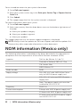
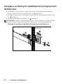
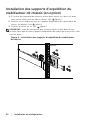
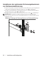
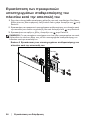
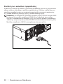
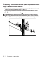
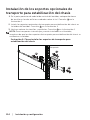
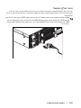
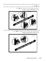
Installing the optional chassis stabilizer
shipping brackets
1. At the back of each vertical rack flange, put two screw bases into the two
square holes above the rail. See
6
in Figure 4.
2. Install the optional chassis stabilizer shipping brackets on the rack flanges.
See
7
in Figure 4.
3. Install and tighten the screws. See
8
in Figure 4.
NOTE: To transport systems already installed in the rack, ensure that the two
chassis stabilizer shipping brackets are in place.
Figure 4: Installing the chassis stabilizer shipping brackets
6
7
8
Back View

Installation and configuration │ 9
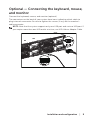
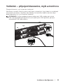
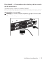
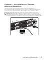
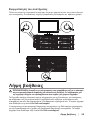
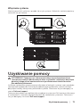
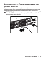
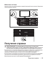
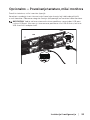
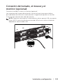
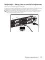
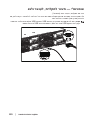
Optional — Connecting the keyboard, mouse,
and monitor
Connect the keyboard, mouse, and monitor (optional).
The connectors on the back of your system have icons indicating which cable to
plug into each connector. Be sure to tighten the screws (if any) on the monitor’s
cable connector.
NOTE: Note that the system supports only one USB port and a micro USB port. If
you require more than one USB outlet at a time, use USB Hub or Adapter Cable.

10 │ Installation and configuration
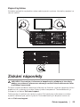
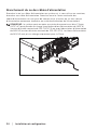
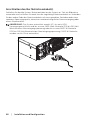
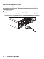
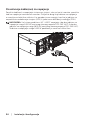
Connecting the power cable(s)
Connect the system’s power cable(s) to the system, and if a monitor is used,
connect the monitor’s power cable to the monitor. Plug the other end of the power
cables into a grounded electrical outlet or a separate power source such as an
uninterrupted power supply or a power distribution unit.
NOTE: The system supports both AC and HVDC power inputs and up to
two1400 W power supply units (200-240 VAC nominal input voltage) or up to
two 1600 W power supply units (200-240 VAC nominal input voltage).
1400 W power supply unit is supported only for China.

Getting help │ 11
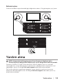
Turning on the system
Press the power button(s) either on the front or at the back of the system. The power
indicators turn green.
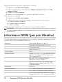
Getting help
WARNING: See the safety and regulatory information that shipped with your
system. Warranty information may be included within this document or as a
separate document.
The Hardware Owner’s Manual provides information about system features and
describes how to troubleshoot the system and install or replace system components.
This document is available at Dell.com/support.
Dell systems management application documentation provides information about
installing and using the systems management software. This document is available
online at Dell.com/support.

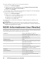
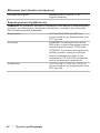
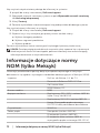
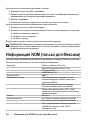
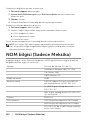
12 │ NOM information (Mexico only)
For an immediate access to your system information:
1. Go to Dell.com/support.
2. Enter your system service tag in the Enter your Service Tag or Express Service
Code field.
3. Click Submit.
4. The support page that lists the system manuals is displayed.
For more information about your system:
1. Go to Dell.com/support.
2. Select your country from the drop-down menu on the bottom right corner of
the page.
a. Select your product category.
b. Select your product segment.
c. Select your product.
The support page that lists the various support categories is displayed.
NOTE: Always check for updates on Dell.com/support and read the updates first
because they often supersede information in other documents.
NOM information (Mexico only)
The following information is provided on the device described in this document in
compliance with the requirements of the official Mexican standards (NOM):
Importer Dell Inc. de México, S.A. de C.V.
Paseo de la Reforma 2620-11° Piso
Col. Lomas Atlas
11950 México, D.F.
Model number B08S
Supply voltage 200-240 V AC with 1400 W (for China
only) or 1600 W power supply unit
100-120 V AC with two 1600 W power
supply units
Note: Two power supply units must be
installed for 100-120 V AC
Frequency 50/60 Hz
Current consumption 9 Amps with 1400 W power supply unit
10 Amps with 1600 W power supply unit
12 Amps with two 1600 W power supply
units at 100-120 V AC

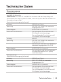
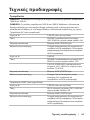
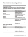
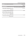
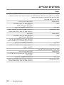
Technical specifications │ 13
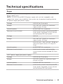
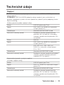
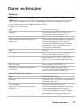
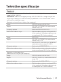
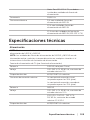
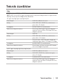
Technical specifications
Power
NOTE: The system does not support mixed installation of 1400 W and 1600 W
power supply units.
NOTE: The 1400 W and 1600 W power supply units are hot swappable, and
support hot swap in any condition if the system has the power throttling feature.
AC power supply (per power supply)
Wattage 1400 W (for China only)
Voltage 200-240 VAC, 50/60 Hz, maximum
input current: 9 Amps
Heat dissipation 6024.376 BTU/hr maximum
Maximum inrush current Initial inrush current cannot exceed 55
Amps (peak). Secondary inrush current
cannot exceed 25 Amps (peak).
Wattage 1600 W
Voltage 200-240 VAC, 50/60 Hz, maximum
input current: 10 Amps
100-120 VAC / 200-240 VAC, 50/60 Hz,
maximum input current: 12 Amps/10
Amps
Heat dissipation 6033.979 BTU/hr maximum
Maximum inrush current Initial inrush current and secondary
inrush current cannot exceed 50 Amps
(peak).
HVDC power supply (per power supply)
Wattage 1400 W (for China only)
Voltage 240 VDC, 50/60 Hz, maximum input
current: 9 Amps
Heat dissipation 5440.614 BTU/hr maximum
Maximum inrush current Initial inrush current cannot exceed 55
Amps (peak). Secondary inrush current
cannot exceed 25 Amps (peak).

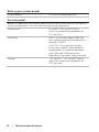
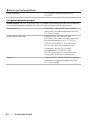
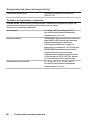
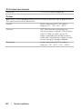
14 │ Technical specifications
Battery (per system board)
System battery 3 V CR2032 lithium coin cell
Environmental
NOTE: For additional information about environmental measurements for specific
system configurations, see Dell.com/environmental_datasheets.
Temperature 10° to 35°C (50° to 95°F) with a
maximum temperature gradation of
10°C per hour
Operating NOTE: For altitudes above 2950 feet,
the maximum operating temperature is
derated 1°F/550 ft.
CAUTION: The maximum number
of memory modules and hard drives
supported on 1U node configuration
with 135W and 145W processors
depends on the power supply installed.
Storage –40° to 65°C (–40° to 149°F) with a
maximum temperature gradation of
20°C per hour

Dell PowerEdge C6320
Příručka Začínáme
Naleznete zde videa s postupy, dokumentaci
ainformace o řešení potíží

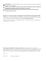
POZNÁMKA: POZNÁMKA označuje důležité informace, které pomáhají klepšímu
využití počítače.
UPOZORNĚNÍ: UPOZORNĚNÍ varuje před možným poškozením hardwaru
nebo ztrátou dat aobsahuje pokyny, jak těmto problémům předejít.
VAROVÁNÍ: VAROVÁNÍ upozorňuje na potenciální poškození majetku a riziko
úrazu nebo smrti.
Licenční smlouva společnosti Dell skoncovým uživatelem
Než začnete systém používat, přečtěte si licenční smlouvu společnosti Dell ksoftwaru
dodávanou se systémem. Jestliže podmínky dané smlouvy nepřijímáte, přejděte na adresu
Dell.com/contactdell.
Veškerá média se softwarem dodávaná se systémem si uložte. Tato média představují záložní
kopie daného softwaru nainstalovaného do systému.
Copyright © 2016 Dell Inc. Všechna práva vyhrazena. Tento produkt je chráněn americkými
amezinárodními autorskými právy adalšími zákony oochraně duševního vlastnictví. Dell
™
alogo
Dell jsou ochranné známky společnosti Dell Inc., vUSA a/nebo dalších jurisdikcích. Všechny
ostatní zde zmiňované značky anázvy mohou být ochrannými známkami příslušných vlastníků.
2016 – 01
Č. dílu CFK9F Rev. A01

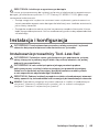
Instalace a konfigurace │ 17
UPOZORNĚNÍ: Umístění somezeným přístupem
Tento server je určen k instalaci pouze na místa s omezeným přístupem, jak jsou
definována v čl. 1.2.7.3 směrnice IEC 60950-1: 2001 kde jsou platné obě podmínky:
• Přístup mohou získat pouze servisní pracovníci nebo uživatelé, kteří byli
poučeni o důvodech omezení platného pro umístění a o veškerých opatřeních,
jež je nutné dodržovat.
• Přístup je poskytován za použití nástroje nebo zámku a klíče nebo je jinak
zabezpečen a je řízen představitelem zodpovědným za toto umístění.
Instalace a konfigurace
VAROVÁNÍ: Před provedením následujícího postupu si přečtěte bezpečnostní
pokyny dodané se systémem apostupujte podle nich.
Instalace ližinového řešení spřístupem bez nářadí
VAROVÁNÍ: Při každém zvedání systému požádejte oasistenci. Systém nezvedejte
sami, vyvarujete se tak zranění.
VAROVÁNÍ: Chcete-li předejít nebezpečí úrazu elektrickým proudem, je nutné
při instalaci racku použít třetí bezpečnostní zemnicí vodič. Rackové vybavení
musí systému poskytovat dostatečný průchod vzduchu a zajišťovat tak
dostatečné chlazení.
UPOZORNĚNÍ: Při instalaci ližin do racku se čtvercovými otvory je důležité
zajistit, aby byly do čtvercových otvorů zasunuty čtyřhranné kolíky.
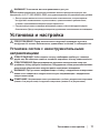
POZNÁMKA: Ližiny lze použít vracku se čtvercovými (položka 1 na následujícím
obrázku) i kulatými otvory (položka 2 na následujícím obrázku).

18 │ Instalace a konfigurace
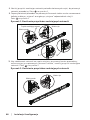
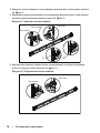
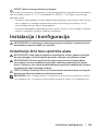
1. Chcete-li otevřít západky ližin, zatlačte na tlačítka ve středu jejich zadních
konců. Viz
1
obrázek1.
2. Zarovnejte koncovky ližin se svislými přírubami racku ausaďte kolíky do
požadovaného spodního ahorního otvoru ve tvaru písmene U. Viz
2
obrázek1.
Obrázek1: Stisknutí tlačítek uvolnění západky
3. Chcete-li uzamknout západky, usaďte konce ližin tak, aby zapadly do svislých
přírub racku, auvolněte tlačítka uvolnění západky. Viz
3
obrázek2.
Obrázek2: Uvolnění tlačítek uvolnění západky
1
2
1
1
2
2
Pohled zezadu
Tlačítko uvolnění západky
Pohled zepředu
3
3
Pohled zezadu
Pohled zepředu

Instalace a konfigurace │ 19
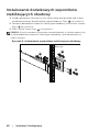
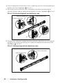
4. Zasuňte systém do racku. Viz
4
obrázek3.
5. Pomocí šroubu upevněte držáky racku kjeho přírubám. Viz
5
obrázek3.
Obrázek3: Instalace šasi do racku
POZNÁMKA: Chcete-li vyjmout ližiny, uvolněte je zatlačením na tlačítko
uvolnění západky ve středu zadního konce ližin.
5
5
4
Pohled zezadu
Pohled zepředu

20 │ Instalace a konfigurace
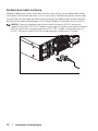
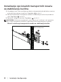
Instalace volitelných stabilizačních přepravních
držáků šasi
1. Na každou svislou přírubu v zadní části racku vložte do dvou čtvercových
otvorů nad ližinou dvě závitové patice. Viz
6
obrázek4.
2. Na zadní příruby racku nainstalujte volitelné stabilizační přepravní držáky šasi.
Viz
7
obrázek4.
3. Namontujte a utáhněte šrouby. Viz
8
obrázek4.
POZNÁMKA: Chcete-li přepravovat systémy již nainstalované vracku, zajistěte,
aby byly tyto dva stabilizační přepravní držáky šasi správně namontovány.
Obrázek4: Instalace stabilizačních přepravních držáků šasi
6
7
8
Pohled zezadu
La page est en cours de chargement...
La page est en cours de chargement...
La page est en cours de chargement...
La page est en cours de chargement...
La page est en cours de chargement...
La page est en cours de chargement...
La page est en cours de chargement...
La page est en cours de chargement...
La page est en cours de chargement...
La page est en cours de chargement...
La page est en cours de chargement...
La page est en cours de chargement...
La page est en cours de chargement...
La page est en cours de chargement...
La page est en cours de chargement...
La page est en cours de chargement...
La page est en cours de chargement...
La page est en cours de chargement...
La page est en cours de chargement...
La page est en cours de chargement...
La page est en cours de chargement...
La page est en cours de chargement...
La page est en cours de chargement...
La page est en cours de chargement...
La page est en cours de chargement...
La page est en cours de chargement...
La page est en cours de chargement...
La page est en cours de chargement...
La page est en cours de chargement...
La page est en cours de chargement...
La page est en cours de chargement...
La page est en cours de chargement...
La page est en cours de chargement...
La page est en cours de chargement...
La page est en cours de chargement...
La page est en cours de chargement...
La page est en cours de chargement...
La page est en cours de chargement...
La page est en cours de chargement...
La page est en cours de chargement...
La page est en cours de chargement...
La page est en cours de chargement...
La page est en cours de chargement...
La page est en cours de chargement...
La page est en cours de chargement...
La page est en cours de chargement...
La page est en cours de chargement...
La page est en cours de chargement...
La page est en cours de chargement...
La page est en cours de chargement...
La page est en cours de chargement...
La page est en cours de chargement...
La page est en cours de chargement...
La page est en cours de chargement...
La page est en cours de chargement...
La page est en cours de chargement...
La page est en cours de chargement...
La page est en cours de chargement...
La page est en cours de chargement...
La page est en cours de chargement...
La page est en cours de chargement...
La page est en cours de chargement...
La page est en cours de chargement...
La page est en cours de chargement...
La page est en cours de chargement...
La page est en cours de chargement...
La page est en cours de chargement...
La page est en cours de chargement...
La page est en cours de chargement...
La page est en cours de chargement...
La page est en cours de chargement...
La page est en cours de chargement...
La page est en cours de chargement...
La page est en cours de chargement...
La page est en cours de chargement...
La page est en cours de chargement...
La page est en cours de chargement...
La page est en cours de chargement...
La page est en cours de chargement...
La page est en cours de chargement...
La page est en cours de chargement...
La page est en cours de chargement...
La page est en cours de chargement...
La page est en cours de chargement...
La page est en cours de chargement...
La page est en cours de chargement...
La page est en cours de chargement...
La page est en cours de chargement...
La page est en cours de chargement...
La page est en cours de chargement...
La page est en cours de chargement...
La page est en cours de chargement...
La page est en cours de chargement...
La page est en cours de chargement...
La page est en cours de chargement...
La page est en cours de chargement...
La page est en cours de chargement...
La page est en cours de chargement...
La page est en cours de chargement...
La page est en cours de chargement...
La page est en cours de chargement...
La page est en cours de chargement...
La page est en cours de chargement...
La page est en cours de chargement...
La page est en cours de chargement...
La page est en cours de chargement...
La page est en cours de chargement...
La page est en cours de chargement...
La page est en cours de chargement...
La page est en cours de chargement...
La page est en cours de chargement...
La page est en cours de chargement...
La page est en cours de chargement...
La page est en cours de chargement...
La page est en cours de chargement...
La page est en cours de chargement...
-
 1
1
-
 2
2
-
 3
3
-
 4
4
-
 5
5
-
 6
6
-
 7
7
-
 8
8
-
 9
9
-
 10
10
-
 11
11
-
 12
12
-
 13
13
-
 14
14
-
 15
15
-
 16
16
-
 17
17
-
 18
18
-
 19
19
-
 20
20
-
 21
21
-
 22
22
-
 23
23
-
 24
24
-
 25
25
-
 26
26
-
 27
27
-
 28
28
-
 29
29
-
 30
30
-
 31
31
-
 32
32
-
 33
33
-
 34
34
-
 35
35
-
 36
36
-
 37
37
-
 38
38
-
 39
39
-
 40
40
-
 41
41
-
 42
42
-
 43
43
-
 44
44
-
 45
45
-
 46
46
-
 47
47
-
 48
48
-
 49
49
-
 50
50
-
 51
51
-
 52
52
-
 53
53
-
 54
54
-
 55
55
-
 56
56
-
 57
57
-
 58
58
-
 59
59
-
 60
60
-
 61
61
-
 62
62
-
 63
63
-
 64
64
-
 65
65
-
 66
66
-
 67
67
-
 68
68
-
 69
69
-
 70
70
-
 71
71
-
 72
72
-
 73
73
-
 74
74
-
 75
75
-
 76
76
-
 77
77
-
 78
78
-
 79
79
-
 80
80
-
 81
81
-
 82
82
-
 83
83
-
 84
84
-
 85
85
-
 86
86
-
 87
87
-
 88
88
-
 89
89
-
 90
90
-
 91
91
-
 92
92
-
 93
93
-
 94
94
-
 95
95
-
 96
96
-
 97
97
-
 98
98
-
 99
99
-
 100
100
-
 101
101
-
 102
102
-
 103
103
-
 104
104
-
 105
105
-
 106
106
-
 107
107
-
 108
108
-
 109
109
-
 110
110
-
 111
111
-
 112
112
-
 113
113
-
 114
114
-
 115
115
-
 116
116
-
 117
117
-
 118
118
-
 119
119
-
 120
120
-
 121
121
-
 122
122
-
 123
123
-
 124
124
-
 125
125
-
 126
126
-
 127
127
-
 128
128
-
 129
129
-
 130
130
-
 131
131
-
 132
132
-
 133
133
-
 134
134
-
 135
135
-
 136
136


