Genius Orion Mode d'emploi
- Catégorie
- Éclairage de confort
- Taper
- Mode d'emploi
La page charge ...

ORION
Guida per l’installatore-Guide for the installer-Guide pour l’installateur
Guía para el instalador-Leitfaden für den Installateur-Gids voor de installateur
Pagina 2
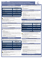
ITALIANO
La fotocellula direzionale con allineamento ORION, composta da un Trasmettitore ed un
Ricevitore a raggi infrarossi modulati, è un dispositivo di sicurezza. L’oscuramento del
fascio luminoso, provoca il cambiamento di stato del contatto elettrico sul Ricevitore.
Alimentazione
24V (19÷35 V )
24V~(21,5÷25,5 V~)
Assorbimento
Tx= 20mA
Rx= 30mA
Portata max. 30 m
IP 54
Tempo rilevamento ostacolo 10mSec
Tipo contatti NO/NC
Portata max. contatti 100mA / 24V
Angolo di rilevazione +/- 4°
Temperatura ambiente -20°C / +55°C
Installazione a parete / su colonnetta
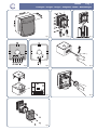
Dimensioni vedi g.1
1. MONTAGGIO
Per un funzionamento ottimale, collocare il Ricevitore e il Trasmettitore allineati.
Nel caso siano previste due coppie di fotocellule, per evitare interferenze
reciproche, disporre i Ricevitori su lati opposti.
Sono possibili due installazioni:
A parete con tubo ad incasso (g. 2 rif. a) o con tubo/guaina esterni (g. 2 rif. b)
Su apposita colonnetta (g. 3)
Eseguire le predisposizioni per i collegamenti elettrici.
Nel caso di installazione a parete, ssare i contenitori ORION con la relativa guarni-
zione utilizzando viti e tasselli idonei.
2. COLLEGAMENTI ELETTRICI
Eseguire i collegamenti elettrici sulle morsettiere del Ricevitore (g. 4) e del Tra-
smettitore (g. 5).
Eseguire i cablaggi elettrici all’apparecchiatura elettronica di comando e ad altre
eventuali fotocellule presenti nell’impianto.
Fare riferimento agli schemi riportati nelle istruzioni delle apparecchiature per le
diverse congurazioni.
Procedere all’allineamento .
3. ALLINEAMENTO
Se la distanza fra il Ricevitore e il Trasmettitore è minore di 15 metri, non eseguire
i punti a,b,c ma saltare direttamente al punto d.
Facendo delicatamente leva con un cacciavite (g.6 ) sollevare il coperchio del
Ricevitore.
Tagliare il ponticello LK1 (g. 7).
Rimontare il coperchio.
Alimentare la fotocellula vericando l’accensione del Led DL1 sul Ricevitore (g.
4) e sul Trasmettitore (g. 5).
Allineare manualmente il Ricevitore e il Trasmettitore orientandoli in senso verticale
e orizzontale, cercando la posizione in cui il Led DL2 sul Ricevitore (g. 4) inizia a
lampeggiare sempre più velocemente.
L’allineamento ottimale si ha quando la frequenza di lampeggio è tale da mantenere
il Led acceso.
Effettuato l’allineamento, serrare la vite di ssaggio (g. 8).
Assemblare la ORION mediante i particolari a corredo (g. 9).
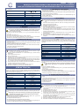
ENGLISH
ORION is a directional photocell with alignment facility consisting of a modular infrared
Transmitter and Receiver. It is classed as a safety device. Breaking the luminous beam
causes the state of the electric contact on the Receiver to be switched.
Power supply
24V (19÷35 V )
24V~(21,5÷25,5 V~)
Input
Tx= 20mA
Rx= 30mA
Max. range 30 m
IP 54
Beam response time 10mSec
Type of contacts NO/NC
Contact rating 100mA / 24V
Detection angle +/- 4°
Ambient temperature -20°C / +55°C
Installation wall / stand
Dimensions see g.1
1. FITTING
In order to ensure optimum working efciency, the Receiver and Transmitter should
be properly aligned.
If two pairs of photocells are to be employed, place the Receivers on opposite
sides in order to avoid mutual interference.
Two types of installation are possible:
Wall with embedded tube (g. 2 item a) or with outer tube/sheath (g. 2- item b).
On special stand (g. 3).
Carry out the work necessary for the electrical connections.
In the case of wall installation, x the ORION enclosures and respective gaskets using
suitable screws and screw anchors.
•
•
•
•
•
•
•
•
a.
b.
c.
d.
e.
f.
g.
h.
•
•
•
•
2. ELECTRICAL CONNECTIONS
Effect the necessary electrical connections to the terminal blocks of the Receiver
(g. 4) and Transmitter (g. 5).
Connect wiring to the electronic control unit and any other photocells present in the
system.
Refer to the diagrams contained in the electronic control unit instructions for details
of the various congurations.
Proceed with alignment.
3. ALIGNMENT
If the distance between Receiver and Transmitter is less than 15 metres, do not
carry out points a,-b,c, but go directly to point d.
Lift the cover of the Receiver by levering slightly with a screwdriver (g. 6).
Cut the jumper LK1 (g. 7).
Ret the cover.
Energise the photocell and check that LED DL1 is lit on both Receiver (g. 4) and
Transmitter (g. 5).
Align the Receiver and Transmitter manually by pointing in a vertical and horizontal
direction, whilst seeking the position in which the LED DL2 on the Receiver (g. 4)
begins ashing ever more rapidly.
Optimum alignment is obtained when the ashing frequency is such as to keep
the LED lit.
Having completed alignment, tighten the xing screws (g. 8).
Assemble the ORION using the components supplied (g. 9).
FRANÇAIS
La photocellule directionelle avec alignement ORION, composée d’un Emetteur et
d’un Récepteur à rayons infrarouges modulés, est un dispositif de sécurité. Quand
le rayon lumineux est couvert, l’état du contact électrique sur le Récepteur subit un
changement.
Alimentation
24V (19÷35 V )
24V~(21,5÷25,5 V~)
Absorption
Tx= 20mA
Rx= 30mA
Portée max 30 m
IP 54
Temps détection obstacle 10mSec
Type contacts NO/NC
Portée max. contacts 100mA / 24V
Angle de détection +/- 4°
Température ambiante -20°C / +55°C
Installation au mur / sur une petite colonne
Dimensions voir g.1
1. MONTAGE
Pour un fonctionnement optimal, placez le Récepteur et l’Emetteur alignés.
Si deux couples de photocellules ont été prévus, pour éviter des interféren-
ces réciproques, placez les Récepteurs sur des côtés opposés.
Il existe deux types d’installation :
Au mur, à l’aide d’un tube à encastrement (g. 2 réf. a) ou avec un tube/gaine
externe (g. 2 réf.b).
Sur une petite colonne prévue à cet effet (g. 3).
Effectuez les préparations nécessaires aux connexions électriques.
En cas d’installation au mur, xez les conteneurs ORION avec leur joint au moyen
de vis et de chevilles adéquates.
2. CONNEXIONS ELECTRIQUES
Effectuez les connexions électriques sur les bornes du Récepteur (g. 4) et de
l’Emetteur (g. 5).
Effectuez les câblages électriques à l’équipement électronique de commande et aux
autres photocellules éventuellement présentes dans l’installation.
Pour les différentes congurations, consultez les schémas gurant dans les instruc-
tions des appareils.
Procédez à l’alignement.
3. ALIGNEMENT
Si la distance entre le Récepteur et l’Emetteur est inférieure à 15 mètres, n’exé-
cutez pas les opérations des points a,b,c mais passez directement au point
d.
En vous servant délicatement d’un tournevis comme levier (g.6), soulevez le
couvercle du Récepteur.
Coupez la barrette LK1 (g. 7).
Remontez le couvercle.
Alimentez la photocellule en contrôlant l’allumage du voyant DL1 sur le Récepteur
(g. 4) et sur l’Emetteur (g. 5).
Alignez manuellement le Récepteur et l’Emetteur en les orientant verticalement et
horizontalement, en cherchant la position dans laquelle le voyant DL2 placé sur le
Récepteur (g. 4) commence à clignoter de plus en plus vite.
L’alignement optimal est atteint lorsque la fréquence de clignotement est telle, que
le voyant reste allumé.
Après avoir effectué l’alignement, serrez la vis de xage (g. 8).
Assemblez la ORION à l’aide des éléments fournis avec l’appareil (g.9).
ESPAÑOL
La fotocélula direccional con alineamiento ORION, está formada por un Transmisor
y un Receptor de rayos infrarrojos modulados, y un mecanismo de seguridad El
•
•
•
•
a.
b.
c.
d.
e.
f.
g.
h.
•
•
•
•
•
•
•
•
a.
b.
c.
d.
e.
f.
g.
h.
La page charge ...

Le descrizioni e le illustrazioni del presente manuale non sono impegnative. GENIUS si riserva il diritto, lasciando inalterate le caratteristiche essenziali dell’apparecchiatura,
di apportare in qualunque momento e senza impegnarsi ad aggiornare la presente pubblicazione, le modiche che essa ritiene convenienti per miglioramenti tecnici o per
qualsiasi altra esigenza di carattere costruttivo o commerciale.
The descriptions and illustrations contained in the present manual are not binding. GENIUS reserves the right, whils leaving the main features of the equipments unaltered,
to undertake any modications to holds necessary for either technical or commercial reasons, at any time and without revising the present publication.
Les descriptions et les illustrations du présent manuel sont fournies à titre indicatif. GENIUS se réserve le droit d’apporter à tout moment les modications qu’elle jugera
utiles sur ce produit tout en conservant les caractéristiques essentielles, sans devoir pour autant mettre à jour cette publication .
Las descripciones y las ilustraciones de este manual no comportan compromiso alguno. GENIUS se reserva el derecho, dejando inmutadas las características esenciales
de los aparatos, de aportar, en cualquier momento y sin comprometerse a poner al día la presente publicación, todas las modicaciones que considere oportunas para el
perfeccionamiento técnico o para cualquier otro tipo de exigencia de carácter constructivo o comercial.
Die Beschreibungen und Abbildungen in vorliegendem Handbuch sind unverbindlich. GENIUS behält sich das Recht vor, ohne die wesentlichen Eigenschaften dieses Gerätes
zu verändern und ohne Verbindlichkeiten in Bezung auf die Neufassung der vorliegenden Anleitungen, technisch bzw, konstruktiv / kommerziell bedingte Verbesserungen
vorzunehmen.
De beschrijvingen in deze handleiding zijn niet bindend. GENIUS behoudt zich het recht voor op elk willekeurig moment de veranderingen aan te brengen die het bedrijf
nuttig acht met het oog op technische verbeteringen of alle mogelijke andere productie- of commerciële eisen, waarbij de fundamentele eigenschappen van het apparaat
gehandhaafd blijven, zonder zich daardoor te verplichten deze publicatie bij te werken.
Timbro rivenditore: / Distributor’s stamp: / Timbre de l’agent: / Sello del reven-
dedor: / Fachhändlerstempel: / Stempel dealer:
Via Padre Elzi, 32
24050 - Grassobbio
BERGAMO-ITALY
tel. 0039.035.4242511
fax. 0039.035.4242600
www.geniusg.com
00058I0258 Rev.2
DICHIARAZIONE CE DI
CONFORMITÁ
Fabbricante: GENIUS S.p.A.
Indirizzo: Via Padre Elzi, 32 - 24050 - Grassobbio-
Bergamo - ITALIA
Dichiara che: Il dispositivo di protezione attiva opto-
elettronico mod. ORION
è conforme ai requisiti essenziali di sicurezza delle
seguenti direttive CEE:
2006/95/CE direttiva Bassa Tensione.
2004/108/CE direttiva Compatibilità Elettro-
magnetica
Nota aggiuntiva:
Questo prodotto è stato sottoposto a test in una
configurazione tipica omogenea (tutti prodotti di
costruzione GENIUS S.p.A.)
Grassobbio, 30 Dicembre 2009
L’Amministratore Delegato
D. Gianantoni
•
•
•
CE DECLARATION OF
CONFORMITY
Manufacturer: GENIUS S.p.A.
Address: Via Padre Elzi, 32 - 24050 - Grassobbio-
Bergamo - ITALY
Declares that: the active optoelectronic safety device
mod. ORION
conforms to the essential safety requirements of
the following EEC directives:
2006/95/EC Low Voltage directive.
2004/108/EC Electromagnetic Compatibility
directive.
Additional information:
This product underwent a test in a typical uniform
conguration (all products manufactured by GENIUS
S.p.A.).
Grassobbio, December 30, 2009
Managing Director
D. Gianantoni
•
•
•
DÉCLARATION CE DE
CONFORMITÉ
Fabricant: GENIUS S.p.A.
Adresse: Via Padre Elzi, 32 - 24050 - Grassobbio-
Bergamo - ITALIE
Déclare que: le dispositif de protection active optoé-
lectronique mod. ORION
est conforme aux exigences essentielles de sécu-
rité des directives CEE suivantes:
2006/95/CE directive Basse Tension.
2004/108/CE directive Compatibilité Électro-
magnétique.
Note supplémentaire:
Ce produit a été testé dans une conguration typi-
que homogène (tous les produits sont fabriqués par
GENIUS S.p.A.)
Grassobbio, 30 décembre 2009
L’Administrateur Délégué
D. Gianantoni
•
•
•
DECLARACIÓN CE DE
CONFORMIDAD
Fabricante: GENIUS S.p.A.
Dirección: Via Padre Elzi, 32 - 24050 - Grassobbio-
Bergamo - ITALIA
Declara que: El dispositivo de protección activa
opto-electrónica mod. ORION
cumple con los requisitos esenciales de seguridad
de las siguientes directivas CEE:
2006/95/CE directiva de Baja Tensión.
2004/108/CE directiva de Compatibilidad
Electromagnética.
Nota adicional:
El presente producto ha sido sometido a ensayos
en una conguración típica uniforme (todos los pro-
ductos han sido fabricados por GENIUS S.p.A.).
Grassobbio, 30 de diciembre 2009
El Administrador Delegado
D. Gianantoni
•
•
•
CE-
KONFORMITÄTSERKLÄRUNG
Hersteller: GENIUS S.p.A.
Adresse: Via Padre Elzi, 32 - 24050 - Grassobbio-
Bergamo – ITALIEN
Erklärt, dass: die aktive optoelektronische Schut-
zeinrichtung Mod. ORION
den wesentlichen Sicherheitsbestimmungen der
folgenden EWG-Richtlinien entspricht:
2006/95/EG Niederspannungsrichtlinie.
2004/108/EG Richtlinie zur elektromagneti-
schen verträglichkeit.
Zusätzliche Anmerkungen:
Dieses Produkt wurde in einer typischen, homoge-
nen Konguration getestet (alle von GENIUS S.p.A.
hergestellten Produkte).
Grassobbio, 30. Dezember 2009
Geschäftsführer
D. Gianantoni
•
•
•
CE VERKLARING VAN
OVEREENSTEMMING
Fabrikant: GENIUS S.p.A.
Adres: Via Padre Elzi, 32 - 24050 - Grassobbio
- Bergamo - ITALIE
Verklaart dat: de actieve opto-elektronische bevei-
liging mod. ORION
in overeenstemming is met de fundamentele
veiligheidseisen van de volgende EEG-richtlijnen:
2006/95/EG Laagspanningsrichtijn.
2004/108/EG richtlijn Elektromagnetische
Compatibiliteit.
Aanvullende opmerking:
Dit product is getest in een specieke homogene
conguratie (alle door GENIUS S.p.A. vervaardigde
producten).
Grassobbio, 30 december 2009
De Algemeen Directeur
D. Gianantoni
•
•
•
-
 1
1
-
 2
2
-
 3
3
-
 4
4


Genius Orion Mode d'emploi
- Catégorie
- Éclairage de confort
- Taper
- Mode d'emploi
dans d''autres langues
- italiano: Genius Orion Istruzioni per l'uso
- English: Genius Orion Operating instructions
- español: Genius Orion Instrucciones de operación
- Deutsch: Genius Orion Bedienungsanleitung
- Nederlands: Genius Orion Handleiding