Sioux Tools 5038B Manuel utilisateur
- Catégorie
- Outils électroportatifs
- Taper
- Manuel utilisateur
Ce manuel convient également à

Operator
Instructions
Includes
-
Foreseen
Use,
Work
Stations,
Putting
Into
Service,
Operating,
Dismantling,
Assembly
and
Safety
Ruies.
Sioux
Tools,
Inc.
1
17
Wi
Drive
Murphy,
NC
28906
U.S.A.
Tel
No.
828-835-9765
Fax
No.
828-835-9685
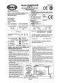
Air
Pressure
- -
--
Product
Net Weight
Recommendedworking
6.2
bar
90
PSI
Maximum
6.2
bar
90
PSI
Recommended
Use
Of
-
---
SAFETY
MESSAGES
I
A
WARNING
Personal
Safety
Equipment
Use-S&tyGIase~
YES
1
Always
Wear
Safety
Use
-
Safety
Gloves
3.75
Ibs
1.70
Kg
Balancer
Or
Support
NO
recommended
conditions.
1
Use
-
Safety
Boots
Use
-
Breathing
Masks
USB
-
Ear
Pme3oss
YES
-If
the
tool
appears
to malfunction,
remove
from
use
immediately
and
arrange for
service
and
repair.
If
it
is
not
practical
to
remove
tool
from
service,
then
shut
off
the
air supply
to
the
tool
and
write
or
have written
a
warning
note
and
attach
it
to
the
tool.
-
If
toot
is
to
be
used
with
a
balancer
or
other
suspension device,
ensure
that
the
tool
is
firmly
attached
lo
the
suspension/support device.
@
Wegr
Hearing
Protection
Avoid
Prolonged
Exposure
A
Important
Read
these
instructions
carefully
before
installing,
operating,
servicing
or
repairing
this
tool.
Keep these
instructions
in
a
safe
Safety
rules
when
using
50380
and
5039B
Impact
Wrenches
-Use
only
impact
sockets
and
extensions,
universal
joints,
etc.
rated
as
being suitable for use
with
impact
wrenches.
-Prolonged
exposure
to
vibration
may cause
injury.
-Read
all
instructions
before
using
this
tool.
AH
operators
must
be
fully
trained
in
its
use
and
aware
of
these
safety
rules.
-
Do
not
exceed
the
maximum
working
air
pressure.
-
Use
personal
protection
equipment
as
recommended.
-
Some
dust
created
by
power sanding,
sawing,
grinding,
drilling,
and
other construction activities contains
chemicals
known
to
cause
cancer,
birth
defects
and
other
reproductive harm.
-Use
only
compressed
air
a?
the
,
accessible
(dace.
Product
Type
3/8"
Square
Drive
Pistol
Grip
Impact
Wrenches
Model
No/Nos
50388
Steel
Nose
Case
Chrome
Plated
5039B
Steel
Nose
Case
Black
Recommended
Hose
Bore
Size
-
Minimum
318ins
10mm
1
Serial
No.
Recommended
Max.
Hose
Length
30
Ft
10
M
Noise
Level:
Sound
Pressure
Level
84.6
dB(A)
Sound
Power
Level
95.6
dB{A)
Test
Method:
Tested
in
accordance
with
Pneurop
test code
PN8KTC1
and
IS0
Standard
3744
Vibration
Level
3.5
Meters
1
Sec2
Test
Method:
Tested
in
accordance
with
IS0
standards
8662
Parts
1
&
7
the body
and
particularly
the
hands
away
from
the
working attachment
fixed
to
the
toot.
-The
tool
is n'ot electrically insulated.
Never
use
the
tool
if
there
is
any
chance
of
corning
into
contact
with
live
electricity.
-
Always
when
using
the
too!,
adopt
a
firm
footing
andfor
position
and
grip
the
tool sufficiently
only
to
overcome
any
reaction
forces
that
may
result
from
the
tool
doing
work.
Do
not
overgrip.
-Use
only
correct
spare
parts
for maintenance
and
repair.
Do
not
improvise
or
make
temporary
repairs.
Major
servicing
and
repairs should only
be
carried
out
by
persons
trained
to
do
so.
-Do
not
lock,
tape,
wire.
etc.
the
'OnIOff'
valve
in
'On'
position.
The
triggernever,
etc.
must
always
be
free
to
Take
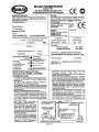
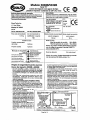
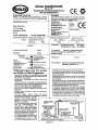
Air
From
Top
A*
Pipe
And
Finings
Stwufd
Se
Iff"
0
Larger
Low
Spot
To
Compressor
with
Sufficient
Capacity
To
Maintain
Recommended
Workig Pressure
Ai
-When
operatinittie
tool.
always
keep
1
Recommended
Air
Supply
System
Figure
1
Page
No
1

return
to
the
'Off'
position when released.
-Always
shut
off
the
air
supply
to
the
tool
and
press
the
'OntOff'
valve
to
exhaust
the
air
from
the
feed
hose
before
fitting,
removing
or
adjusting the working
attachment fitted
to
the
tool.
-Before
using
the
tool,
make
sure
that
a
shut
off
device
has
been
fitted
to
the
air
supply line
and
the
position
is
known and
easily
accessible
so
that
the
air supply to
the
tool
can
be
shut
off in
an
emergency.
-Check
hose
and
fittings
regularly
for
wear-
-Take
care against entanglement
of
the
moving
parts
of
the tool with
clothing,
hair,
ties,
cleaning
rags,
rings,
jewelry,
watches,
bracelets,
etc.
This
could
cause
the
body
or
parts
of
the
body
to
be
drawn towards
and
in
contact
with
the
moving
parts
of
the
tool
and
could
be
very dangerous.
-It
is
expected that users will
adopt
safe
working
practices
and observe all
local,
regional
and
country
legal
requirements
when
installing,
using
or
maintaining the
tool.
-Take
care
that
the
exhaust
air
does
not
point
towards
any
other person or material
or
substance
that
could
be
contaminated
by
oil
droplets.
When first lubricating
a
tool
or
if
the
tool
exhaust
has
a
high
oil
content,
do
not
allow
the
exhaust
air
to
come
near
very
hot
surfaces
or
flames.
Never
lay
the
tool
down
until
the
working
attachment
has
stopped
moving.
-When
the
tool
is
no?
in
use,
shut
off
the air
supply
and
press the triggerflever
to
drain the
supply
line.
If
the
toot
is
not
to
be
used
for
a
period
of
time,
first
lubricate,
disconnect
from air
supply
and
store
in
a
dry
average
room
temperature
environment.
-If the tool
is
passed
from
one
user
to
a
new
or
inexperienced
user,
make
sure
these instructions are
passed
with
the
tool.
-
Do
not remove
any
manufacturer fitted
safety
devices
where
fitted,
i.e.,
wheel
guards,
safety
trigger,
speed
governors,
etc.
-Wherever
possible,
secure
workplace
with
clamps,
a
vise, etc.
to
make
it
rigid
so
it
does
not
move
during
the
work operation.
Keep
good
balance
at
all
times.
Do
not
stretch
or
overreach.
-Try
to
match
the
too!
to
the
work
operation.
Do
not
use
a
tool
that
is
too
light
or
heavy
for the work
operation.
If
in
doubt,
seek
advice.
-in general
terms,
this
too!
is
not suitable
for
underwater
use
or
use
in
explosive
environments
-
seek
advice
from
manufacturer.
-Try to
make
sure
that
the
work
area
is dear
to
enable
the
work
task to
be
performed
safely.
If
practical
and
possible,
try
to
clear
unnecessary
obstructions
before
starting
work.
-Always
use
air
hose
and
couplings with minimum
working
pressure
ratings
at
least
1
112
times
the
maximum
working
pressure
rating
of
the
tool.
Foreseen
Use
Of
The
Tool
-
5038Bl
50396
The
impact wrench
is
designed
for
the tightening
and
loosening
of
threaded fasteners within the range
as
specified
by
the
manufacturer It
should
only
be
used
10
conjunction with
suitable
impact
type
318'
square
female
drive
nut running
sockets.
Only
use
sockets
which
are
of
the impact
type.
It is allowed to use suitable extension
bars.
univefsat
joints
and
socket
adaptors between
the
square output drive
of
the
impact
wrench and the square
female
drive
oi
the socket.
Do
not
use
the tool
for
any
other purpose than that
specified
without consulting the manufacturer
or
the manufacturer's
authorized supplier
To
do
so
may
tie
dangerous,
Never
use
an impac! wrewhas
a
hammer
to dislodge or straighten
cross threaded fasteners.
Never
attempt to
modify
the
tool
fw
other
uses and never modify
the
too) for even
its
recommended
use
as
a
nutrunner
Work
Stations
-
The
tool
should
only
be
used
as
a
handheld, hand operated tool.
It
is
always
recommended that the tool
is
used
when
standing
on the
solid
floor.
It
can
be
used
in other positions. but
before
any
such
use,
the
operator
must
be
in
a
secure position having
a
firm grip
and
footing
and
be
aware that
when
loosening
fasteners
the
tool
can
move quite quickty
away
from
the fastener being undone. An
allowance must
always
be
made
for this rearward movement
so
as
to
avoid
the oossibilitv
of
hand/arm/bodv entrapment.
-
Page
Putting
Into
Service
-
No
2
Air
Supply
Use
a
clean lubricated
air
supply
that will give
a
measured air
pressure
at
the
tool
of
90
p.s.i.16.2
tsar when the tool
is
running
with
the trigger fully depressed and the air regulator in its
maximum opening flow position. Use recommerided hose
size
and
length.
1;
is recommended that the tool
is
connected to the air
supply as
shown
in figure
1.
Do
not
connect
a
quick
connect
coupling directly to
the
8001,
but
use
a
whip or leader hose
of
approximtely
12
inches length.
Do
not connect the tool to the air
line
system
without incorporating
an
easy
to reach
and
operate air
shut off valve. The air supply should
be
lubricated.
It
is
strongly
recommended
that
an air filter, regulator, lubricator
(FRL)
is used,
as
shown
in Figure
1,
as
this will supply
clean,
lubricated airat the
correct
pressure to the tool. Details of such equipment
can
be
obtained
from
your
supplier.
If
such
equipment is not
used.
then
the tool should
be
lubricated
by
shutting
off
the air
supply
40
the
tool, depressurizing the line
by
pressing
the
ihronle lever on the
too). Disconnect the air line and pour into
the
hose
adaptor
(9)
a
teaspoonful
(5ml)
of
a
suitable pneumatic motor lubricating oil
preferably incorporating
a
rust inhibitor. Reconnect tool
to
air
supply and run
tool
slowly
for
a
few seconds to allow air to
circulate the oil.
If
tool is used frequently, lubricate
on
daily
basis
and
if
tool
starts
to
slow
or
lose power.
When
lubricating, also
ensure
that the air strainer in hose adaptor
(9)
is clean.
It is
recommended
that joint tightness of
the
threaded fastener
assembly
be
checked
with suitabie
measuring
equipment.
It is recommended that the air pressure
a!
the
tool
while
the
tool
is
running
is
90
p.s.i./6.2
bar.
Operating
The
output
of
the
impact
wench in prime working condition is
governed
by
mainly three factors:
a)
the
input
air
pressure;
b)
the
time
the
impact
wrench
is
operated
on
the joint. Normal
time
for
joints of average tension requirement
3
to
5
seconds;
c)
the
selling
of
the
air
regulator
for
a
given joint
at
a
given pressure
operated
for a
given time.
The
air regulator
(26)
can
be
used
to regulate the output of the
impact
wench
if
no
other
means
of
control is available.
It
is
strongly
rmmded that
an
external
pressure
regulator, ideally
as
part
of
a
filter/rqulator/ltibricator
(FRL).
is
used
to control air inlet pressure
so
that
the
pressure
can
be
set to help control the tension required
to
he
applied
to
Ihe
threaded fastener
joint
There is
no
consistent. reliable torque adjustment
on
an
impact
wrench
of
this
type.
However,
the
air regulator
can
be
used
to
adjust
torque
to theapproximate tightnessof
a
known
threadedjoint.Toset
the toolto
the
desired torque, select
a
nut or
screw
of
known
tightness
of
the
same
size,
thread
pitch
and
thread
condition
as
those
on
(tie
job.Turn
air
regulator
to
low
position,
apply
wrench
$0
nut
and
gradually increase
power
(turn
regulator
to
admit
more
air) until
nut
moves
slightly
if!
the direction it
was
originally
set.The
tool is
now
set
to duplicatethat tigMness,
note
regulatorsetting for future use.When
tightening nuts
not
requiring critical torque values,
run
nut
up
Hush
and then
tighten
an
additional
one-quarter to
one-half
turn
(sBght
additfonal turning is necessary if gaskets are being
damped).
For
additional power
needed
on
disassembly work, turn regulator to its
fully open position.
This
impact
wrencti
is
rated
a
3/8"
bolt
size.
Rating must
be
downgraded
far
spring
U
bolts, tie
bolts,
long
cap
screws, double depth
nuts,
badly
rusted conditions
and
spring
fastenersas
they
absorb
much of the impact power. When possible,
clamp
or wedge
the
bolt
to
prevent
springback.
Soak
rusted nuts
in
penetrating oil
and
break rust seal before
removing
with
impact wrench.
tf
mt
does
rat start
to
move
in
three
to
five
seconds
use
a
larger
size
impact wrench.
Do
not
use
impact
wrench
beyond rated
capacity
as
this will drastically reduce tool life.
NOTE:
Actual torque on a fastener is directly related
to
joint
hardness, tool
speed,
condition
of
socket
and the time
me
tool
is
allowed
to
impact.

3)
AteaysyseStS~owectsiii&Si^acttypesocket
2)
Use
extra
(Seep
aocfceES
in
piSCft
03
exiewfoti
bars
where
lÈs$ibte
3)
&onotusewss^Kf.wornwaaticeasocteis.
4)
MofetBwwrenchsotiieSOCK(Mfitssquara-iyon!hefastener.Hofsf
the
wrench
Srw!~
bat
not
too
tightty,
ptesskig
forward
sSigitB^
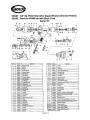
Dismantiing
Sc
Assembly
Instructions
Disconnect
toot
iwm
air
supply.
Take
out
oil
plug
(2)
swd
ttcaxi
ttw
(ttt
wntaioed
in
the
fron
eeoct
of
the
toot
into
a
suitable
corrtainer.
Grip
motor
housing
(1)
in
a
vise
fitted
with
soft
jaws
and
unscrew
4
screws
with
washers
(33)
and
pull
off
housing
(46)
as
fitted
and
ramova
O-ring
(45).Oil
seat
(47)
may
be
hooked
out
of
arri
awil
bushing
(44)
pressed
out
of
housing
(46).
Remove
anvil
Spacer
(41).
PuH
off
the
hammer
mechanism
completely
awl
pull
it
apart
to
separate
anvil
(40)
or
(49).
spring
(39).
2
hammer
pins
(37),
hammer
cam
(381,
cam
ball
(36).
cam
ball
pilot
(35)
and
hammer
cage
(34).
Socket
ring
(43)
and
0'rii'~
(4S)
may
b
pried
off
awil(40)
but
do
not
try
to
remove
assembly
iterris
(SO)
(coif)
anvil
(49).
Remove
4
screws
with
washers
(33)
ana
carefully
pull
off
end
cap
(28)
and
gas-fet
(29)
completewith
air
regulator
assembly.
Remove
C-ring (30)
and
regulator
swefMAy
may
be
pullet) through
end
cap
(28)
being
careful
not
to
tose
spring
(31)
and
steel ball
(32)
Remove
O-ring
(27)
ffotti
air
regulator
reverse
(26).
Note
in
particular
the
orientationof
the
parts
to
each
other
for
reassembly.
Unscrew
how
adaptor
{&)
and
take
off
exhaust
dettector
<8).
Pull
out
rear
end
plate
(24)
frith
bait
beating
(25).
TOW
(22).
cylinder
{20).
guide
pin
(23)
and
G
row
blades
<£?
from
motorhousing
(1).
Tap
out
fromendpiate
(19)
completewithO+nog
(13),
oil
sea)
{I?)
and
bat!
tearing
($6)
from
Iwysing
{f).
Bat1
bearing
<2S)
may
be
lapped
out
of
rear
and
plate
(24)
and
oil
$MI
<1?)
arrf
&&I
beating
(IS)
retrieved!mton!
pMe{?9}.fiemove2$(yews
(iS)atçicare
fuBywSsiosx!fpttSwttrigawass~hemhOTisung{I).The
Uiggaassail(naybasepwatediWparts.iriggerpaifKLstop
mwi-
US),
Â¥{hwai
btisttitjg
<*,
O-fifOS
(1
1)
an3
E-r&j
(3).
Nste
the
SoeaBsn
arri
onentaaw
of
aii
pass
(w
fsas?w*3y.
Reassembly
Ctean
aii
parts
and
waroKia
iw
wear
arwi
cracte.
eit;.
and
repiacs
as
necessary.
Loot;
in
partkoiar
fa:
wear
antf
curs
oo
0-tiwjs
and
seais
awl
war
on
row
bia<tes.
Lot*
for
waat
and
cracks
on
piam
of
th@
hammer
mscfiacAsm
paqicotarty
in
Ihs
area
of
the
square
drive
an
arwils'
(40)
or
(49).
RspIace
all
parts
are
necessary
with
manufacturer
or
authorial
distribmor
supplied
parts.
Make
sure
that.
the
faces
of
end
plates
(19)
and
{24}
That
abut
cylinder
(20)
are
itat
and
free
ifom
surface
detects
anti
bum.
If
necessary.
lap
faces
with
a
vary
twin.
grade
of
abrasive
paper.
Ugh*
coat
aH
parts
with
a
suitable
pneumatic
twl
lybricalinfl
Oil
anC!
asseffif&le
in
the
reverse
order.
On
completing
assembly,
emure
that
all
pans
are
locked
tight,
the
anvil
will
rotate, and
the
trigger
re
vatve
and
air
regulate
mechanism
operate
freeiy.
Reiftow
oil
plug
(2)
and
pour
is
38
fl.
oz.
{iZcc)
of
a
standard SASM)
gradti
oit.
Do
not
(werfia
as
this
wit!
wstjK
in
a
iedu&r>
in
pettoranee.
Pour
in
awm.
5
mi
oi
a
good
quafay
fubfiaaiq
04
<ow
prefefSSiy
contaiaiRg
a
mi
ittht&ttor)isto
tfte
(rose
a&#tw
(9)
with
the
aitgswdepressed.Confleciloaswtabfe&staspiyawlruniheto<a
foi
a
few
secortds
ta
a8aw
Ihe
oiS
to
cirwhls
and
reset
fof
operaikiS.
Refer
K;
seem
Operating.
As;
CQft~ymc&M
I
3.5
cte>
(25
ach)
lifaMmum
Tow
Reverse
1
2iO
tt.
!bs.
(285
?0)
Wortang
Toque
Reverse
1
S185
f(.
W.
(08-251
Nm}
Maximum
Torque
Forward
Witibs.
pi51
Mm)
----,-
Working
Torque
Forward
I
50-160ft.IteS.(68-217Nm)
~ir
Inlet
?l'arsatf
I
\"
W~SMPT
Overall
Length
1
6.25-
(159
mm)
at
90
PSIW6.2
bar
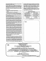
Declaration
of
Conformity
"N
Sioux
Tools,
Inc.
117
Levi
Drive,
Murphy,
NC
28906,
U.S.A.
declare
under
our
sole
responsibSty
that
the
product
Model
5038Bl5039B Impact
Wrenches,
Serial
Number
to
which
this
declaration
relates
is
in
conformity
with
the
following
standard($)
of
other
normative
docurnent(s)
EN792 (Draft),
EN292
Parts
1
&
2,
IS0
8662
Parts
1
&
7,
Pneurop
PN8NTC1
foliowing
the
provisions
of
891392EEC
as
amended
by
91/368/EEC
&
93144EEC
Directives
@
tA-
G
a
.
Seebeck
(President)
Primed
in
Japan
Page
No
3

Modele
5038Bl5039B
Srie
"B"
Cles
a
chocs
a
poignk
pistolet
avec
carre
conducteur
de
3/8
po
(93
mm)
ce
-
~
Instructions
de
fonctionnement
Comprend
:
Utilisation
pf<'vue,
stations
de
travail,
mise
en
service,
fonctionnement,
demontage, montage
et
rfrgles
de
s6curit6,
Sioux
Tools,
Inc.
1
17
Levi Drive
Murphy,
NC
28906
U.S.A.
Tel
No.
828-835-9765
Fax
No.
828-835-9685
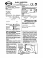
Poids
net
du
produit
*
Emploi conseille
d'un
1,70
kg
diisposftif
d'6qui
lib
rage
ou
d'un
support.
NON
Pression
#air
De
fonctionnement
recommandee
6,2
bar
Maximum
6,2
bar
Regles
de
securite
pour
I'emploi
des
cles
a
chocs
5038B/5039B
Employez
seulement
des
dauilles,
rallonges,
cardans,
etc.
pour
de
a
choc
qui
respondent
aux
conditions
nominales
de
ionctionnement de la cl4
a
chocs.
Une
exposition
prolongbe
aux
vibrations
pent
causer
des
blessures.
Lisez
les
instructions
avant
d'employer
cet
outil.
Tous
Ie
~Derateurs
doivent connaitre ~artaiternenl
son
utitisation
ei
connartre
ces
rdgles
de
s&rite.
Ne
depassez
pas
la
pression d'air
de
foncfionnement
maximum.
Employez
r6quipement
de
protection
pereonnelle
recornman&.
Certaines
poussiferes
engendrees
par
le
pondage,
Ie
sciage,
Ie
meulage,
le
pereage
pneumatique
et
d'autres
activites
de
construction
contiennent
des
produits
chimiques
qui
sont
connus
cornme
,.
provoquant
ie
cancer,
des
anomalies
conaenitales
et
d'autres
troubles
son
aire
de
service,
dtez
Fairiv&
(fair
et
fixez
une
note (favertissement
manuscrite
a
ra.
Si
i'oulil
doit
ktre
employ&
avec
un
dispositif
rf^quiftorageou
de
suspension,
assurez-vous
que
I'ouW
est
bien
fix4
ace
systhe
de
suspension
ou
de
support.
Important
Usez
attentivement
ces
instructions
avant
d'installer.
de
faire
fonctinnner.
d'entretmir
(MI
de
knaref
cet
outil-
Gardez
ces
-
-
- -
-
-
-
-
-
7
- -
---
--
--
instmctlons
dans
un
endroit
&
et
fachent
accessible.
Fype
de
produit
Cles
$i
chocs
poigmk
3.m
pistolet
avec
carre
ttmin
~onducteur
de
3/8
PO
10
mrn
10
rn
Niveau
sonore:
Niveau
de
pression
sonore
84,6
dB(A)
Niveau
de
puissance
sonore
95,6
dB(A)
Methode
de
test
Test4
selon Ie
code
de
test
Pneurop
PN8fn"Cl
et
la
nonne
IS0
3744.
Niveau
de
vibrations 3,5
rn/s2
Methode
detest:
test&
seton
les
norrnes
IS0
8662,
sections
1
&
7
Quand
vous
employez
I'outil
,
tenez
toujours
Ie
corps
et
les
mains
a
1'ecart
des
accessoires
de
travail
fixes
a
I'outil.
Cet
outil
n'est
pas
isde
6lectriquemenL
N'employez
jamis
cet
outil
si
vous
risque2
d'entrer
en
contact
avec
de
relectridte.
Quand
vous
employez
cet
outil,
prenez
une
position ferrne
et
tenez
Men
I'outit
pour
compenser
toutes
forces
de
reaction
qui
pourraient
etre
caudes
par
Ie
fonctionnement
de
I'outit.
Ne
sen-ez
pas
trop
fort
dans
les
mains.
-
Employez
seulement
des
pieces
de
rechange
correctes
pour
rentretien
et
les
reparations.
N'irnprovisez
pas
de
rkparations
temporaires.
L'enlretien
et
!es
reparations
ne
doit
etre
eifectuees
que
par
du
personnel
quafifie.
Ne
btoquez
pas
les
valves
"OdOff
en
position
dans
la
position
"On"
(en
service). Le levier
de
commando
doit
toujows
etre
libre
de
retourner
dans
la
position
"Off
(hors
service)
wand
on
Ie relache.
Arretez
toujours
I'arfivee
$air
&
I'outil
et
appuyez
sur
4a
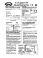
Svsterne
(fatimentation
&air
recommande
Fiaure
1
Page
No
4


-
 1
1
-
 2
2
-
 3
3
-
 4
4
-
 5
5
-
 6
6
-
 7
7
-
 8
8
-
 9
9
-
 10
10
-
 11
11
-
 12
12
-
 13
13
-
 14
14
-
 15
15
-
 16
16
-
 17
17
-
 18
18
-
 19
19
-
 20
20


Sioux Tools 5038B Manuel utilisateur
- Catégorie
- Outils électroportatifs
- Taper
- Manuel utilisateur
- Ce manuel convient également à
dans d''autres langues
- English: Sioux Tools 5038B User manual
Documents connexes
-
Sioux Tools IW38TBP-2Q Operator Instructions Manual
-
-
-
-
-
-
-
-