Sollae Systems CIE-M10 Manuel utilisateur
- Taper
- Manuel utilisateur

Sollae Systems Co., Ltd.
https://www.ezTCP.com
8ports Remote I/O Controller
CIE-M10 User Manual
Version 3.4

CIE-M10 User Manual Ver. 3.4
- 1 -
https://www.ezTCP.com
This symbol, found on your product or on its packaging, indicates that this
product should not be treated as household waste when you wish to dispose
of it. Instead, it should be handed over to an applicable collection point for the
recycling of electrical and electronic equipment. By ensuring this product is
disposed of correctly, you will help prevent potential negative consequences to the
environment and human health, which could otherwise be caused by inappropriate disposal
of this product. The recycling of materials will help to conserve natural resources. For more
detailed information about the recycling of this product, please contact your local city
office, household waste disposal service or the retail store where you purchased this
product.
※ This equipment obtained certification by using 1.5M serial cable.

CIE-M10 User Manual Ver. 3.4
- 2 -
https://www.ezTCP.com
Contents
Contents ............................................................................................................................................ - 2 -
1 Introduction ............................................................................................................................. - 6 -
1.1 Introduction .......................................................................................................................................................... - 6 -
1.2 Features .................................................................................................................................................................. - 6 -
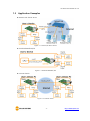
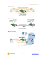
1.3 Application Examples ....................................................................................................................................... - 7 -
1.4 Specification ......................................................................................................................................................... - 9 -
1.4.1
H/W specification ..................................................................................................................................... - 9 -
1.4.2
S/W specification ...................................................................................................................................... - 9 -
1.5 Interface .............................................................................................................................................................. - 10 -
1.5.1
Dimension ................................................................................................................................................. - 10 -
1.5.2
Pin assignment ....................................................................................................................................... - 11 -
1.5.3
Digital Input Ports ................................................................................................................................. - 12 -
1.5.4
Analog Input Port .................................................................................................................................. - 13 -
1.5.5
Digital Output Ports ............................................................................................................................. - 13 -
1.5.6
Ethernet Interface .................................................................................................................................. - 14 -
1.5.7
RS232 Port (DB9M) ............................................................................................................................... - 14 -
1.5.8
System LED ............................................................................................................................................... - 15 -
2 Installation and Test ............................................................................................................ - 16 -
2.1 Installation .......................................................................................................................................................... - 16 -
2.1.1
Setting Network Aera .......................................................................................................................... - 16 -
2.2 Test operation ................................................................................................................................................... - 18 -
2.2.1
Modbus/TCP Test ................................................................................................................................... - 18 -
2.2.2
HTTP Test with a WEB browser ....................................................................................................... - 20 -
3 Configuration ....................................................................................................................... - 21 -
3.1 Configuration with ezManager ................................................................................................................. - 21 -
3.1.1
Configuration via LAN ......................................................................................................................... - 21 -
3.1.2
Configuration via Serial ...................................................................................................................... - 22 -
3.2 AT command ..................................................................................................................................................... - 23 -
4 Operation Modes ................................................................................................................ - 24 -
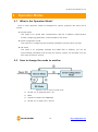
4.1 What is the Operation Mode? .................................................................................................................. - 24 -
4.2 How to change the mode to another .................................................................................................. - 24 -
4.3 Comparison of the each mode ................................................................................................................ - 25 -
4.4 Normal Mode ................................................................................................................................................... - 25 -

CIE-M10 User Manual Ver. 3.4
- 3 -
https://www.ezTCP.com
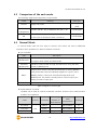
4.5 Serial Configuration mode ......................................................................................................................... - 26 -
4.5.1
Configuring Parameters ...................................................................................................................... - 26 -
4.5.2
Revoking Serurity Options................................................................................................................. - 26 -
4.6 ISP mode............................................................................................................................................................. - 26 -
4.6.1
Upgrading Firmware............................................................................................................................. - 26 -
4.6.2
Upgrading HTML ................................................................................................................................... - 26 -
4.6.3
Revoking Serurity Options................................................................................................................. - 26 -
5 Methods for I/O control .................................................................................................... - 27 -
5.1 Modbus/TCP ...................................................................................................................................................... - 27 -
5.1.1
.Related Parameters .............................................................................................................................. - 27 -
5.1.2
Modbus/TCP Slave Mode .................................................................................................................. - 28 -
5.1.3
Modbus/TCP Master Mode ............................................................................................................... - 28 -
5.1.4
TCP Connection Modes ...................................................................................................................... - 29 -
5.1.5
Initial State ................................................................................................................................................ - 29 -
5.1.6
Write Pulse ................................................................................................................................................ - 29 -
5.2 Serialized Modbus/TCP ................................................................................................................................ - 29 -
5.3 Macro Mode ...................................................................................................................................................... - 30 -
5.3.1
Operator ..................................................................................................................................................... - 30 -
5.3.2
Operand ..................................................................................................................................................... - 30 -
5.3.3
An Example of Equations ................................................................................................................... - 31 -
5.4 Web (HTTP) ........................................................................................................................................................ - 32 -
5.4.1
Changing the Web(HTTP) port ....................................................................................................... - 32 -
5.4.2
Uploading Users’ Web Page ............................................................................................................. - 33 -
6 Communication Modes ...................................................................................................... - 34 -
6.1 TCP Server .......................................................................................................................................................... - 34 -
6.1.1
Key parameters ....................................................................................................................................... - 34 -
6.1.2
An Example ............................................................................................................................................... - 35 -
6.2 TCP Client ........................................................................................................................................................... - 36 -
6.2.1
Key parameters ....................................................................................................................................... - 36 -
6.2.2
An Example ............................................................................................................................................... - 37 -
6.3 AT Command .................................................................................................................................................... - 39 -
6.3.1
Key parameters ....................................................................................................................................... - 39 -
6.3.2
Examples .................................................................................................................................................... - 40 -
6.4 UDP ....................................................................................................................................................................... - 42 -
6.4.1
Key parameters ....................................................................................................................................... - 42 -
6.4.2
Examples .................................................................................................................................................... - 43 -

CIE-M10 User Manual Ver. 3.4
- 4 -
https://www.ezTCP.com
7 System Management .......................................................................................................... - 45 -
7.1 Upgrading Firmware ...................................................................................................................................... - 45 -
7.1.1
Firmware .................................................................................................................................................... - 45 -
7.1.2
Processes ................................................................................................................................................... - 45 -
7.2 Changing Webpage ....................................................................................................................................... - 47 -
7.2.1
Webpage ................................................................................................................................................... - 47 -
7.2.2
Processes ................................................................................................................................................... - 47 -
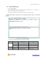
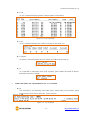
7.3 Status Monitoring ........................................................................................................................................... - 50 -
7.3.1
Using TELNET .......................................................................................................................................... - 50 -
7.3.2
Using ezManager ................................................................................................................................... - 52 -
8 Additional Functions ........................................................................................................... - 54 -
8.1 Security ................................................................................................................................................................ - 54 -
8.1.1
Restriction of Access (ezTCP Firewall) .......................................................................................... - 54 -
8.1.2
Setting Password .................................................................................................................................... - 54 -
8.2 Option Tab Functions .................................................................................................................................... - 55 -
8.2.1
Notify IP Change ................................................................................................................................... - 55 -
8.2.2
Sending MAC Address ........................................................................................................................ - 56 -
8.2.3
Debugging Message ............................................................................................................................ - 56 -
8.3 Serial Port Tab Functions ............................................................................................................................. - 58 -
8.3.1
TELNET COM port Control Option (RFC 2217) - ① .............................................................. - 58 -
8.3.2
Disable TCP Transmission Delay - ② ........................................................................................... - 58 -
8.3.3
Data Frame Interval - ③ .................................................................................................................... - 58 -
8.3.4
TX interval - ④ ....................................................................................................................................... - 59 -
8.3.5
TCP Server / Client mode - ⑤ ........................................................................................................ - 59 -
8.3.6
Separator - ⑥.......................................................................................................................................... - 59 -
8.4 I/O Port Tab Functions ................................................................................................................................. - 60 -
8.4.1
Notify Input Port Change .................................................................................................................. - 60 -
8.4.2
Valid Time .................................................................................................................................................. - 60 -
8.4.3
Delay ............................................................................................................................................................ - 60 -
9 Self-Test in Trouble ............................................................................................................. - 61 -
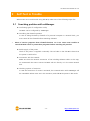
9.1 Searching problem with ezManager ...................................................................................................... - 61 -
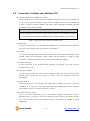
9.2 Connection Problem over Modbus/TCP .............................................................................................. - 62 -
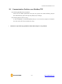
9.3 Communication Problem over Modbus/TCP ..................................................................................... - 63 -
10 Technical Support and Warranty ...................................................................................... - 64 -
10.1 Technical Support ........................................................................................................................................... - 64 -
10.2 Warranty .............................................................................................................................................................. - 64 -

CIE-M10 User Manual Ver. 3.4
- 5 -
https://www.ezTCP.com
10.2.1
Refund ......................................................................................................................................................... - 64 -
10.2.2
Free Repair Services ............................................................................................................................. - 64 -
10.2.3
Charged Repair Services..................................................................................................................... - 64 -
11 Precaution and Exemption from Liability ....................................................................... - 65 -
11.1 Precaution........................................................................................................................................................... - 65 -
11.2 Exemption from Liability .............................................................................................................................. - 66 -
11.2.1
English version ........................................................................................................................................ - 66 -
11.2.2
French version ......................................................................................................................................... - 66 -
12 Revision History ................................................................................................................... - 69 -

CIE-M10 User Manual Ver. 3.4
- 6 -
https://www.ezTCP.com
1 Introduction
1.1 Introduction
In the era of Ubiquitous Environments, many kinds of systems which use sensors like
temperature, humidity or pressure and controlling the power of remote devices have been
developing. CIE-M10 monitors those sensors and controls the remote devices. It detects
digital inputs from the sensor’s outputs and controls the relay outputs. HTTP, Modbus/TCP,
serialized Modbus/TCP and Macro mode can be used for these functions. CIE-M10 can be
used in another way because it equipped operation as a serial device server.
1.2 Features
⚫ Remote I/O controller
⚫ Module type with a built-in RJ45 connector for Ethernet interface
⚫ 8 Digital Input Ports (3.3V CMOS)
⚫ 8 Digital Output Ports (3.3V CMOS)
⚫ 1 x Analog Input Port (10 bits resolution ADC)
⚫ Supports Modbus/TCP and HTTP
⚫ Stored Web server for simple management (custom web page)
⚫ Supports serialized Modbus/TCP
⚫ MACRO (stand-alone operation supports simple logical expressions)
⚫ Stable embedded TCP/IP stack
⚫ easy configuration program (ezManager)


CIE-M10 User Manual Ver. 3.4
- 9 -
https://www.ezTCP.com
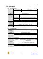
1.4 Specification
1.4.1 H/W specification
Power
Input Power
3.3V (±10%)
Current Consumption
190mA typical
Size
64.4mm x 40mm x 17mm
Weight
Approximately 17g
Interfaces
Digital Input
8 digital input ports (3.3V CMOS logic level)
Analog Input
1 ADC port (10-bit resolution)
Digital Output
8 digital output ports (3.3V CMOS logic level)
Serial Port
1 UART (300~230,400 bps), RTS/CTS Flow Control,
3.3V level (5V tolerant)
Ethernet
RJ45
Network
Ethernet 10Base-T or 100Base-TX (Auto-Sensing)
Auto MDI/MDIX(Cable Auto-sensing)
Temperature
Operate: 0 ~ 70℃ / Storage: -40 ~ 85℃
Environment
Follows Europe RoHS Directive
Table 1-1 H/W specification
1.4.2 S/W specification
Protocol
TCP, UDP, IP, ICMP, ARP, DHCP, DNS lookup, DDNS,
Telnet COM Port Control Option(RFC2217), Modbus/TCP, HTTP
Diagnose
Online Debugging Function
Operation
mode
Normal
Normal communication mode
ISP
F/W upgrade
Serial
Configuration
Configuration with the RS232 port
Communication
Mode
I/O server
Modbus/TCP – Slave/Master, Passive/Active
Web Browser(HTTP), Macro(Stand-alone), Serialized
Modbus/TCP
Serial devices
server
TCP Server/Client, AT emulation, UDP
Programs
ezManager
Configuration program via LAN
ModMap
Modbus/TCP Application for Windows
Table 1-2 S/W specification

CIE-M10 User Manual Ver. 3.4
- 10 -
https://www.ezTCP.com
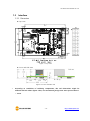
1.5 Interface
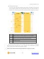
1.5.1 Dimension
⚫ Top view
Figure 1-7 Top view
⚫ Front and Side view
Figure 1-8 Front and Side view
According to conditions of soldering components, the real dimensions might be
differed with the above figure. Thus, we recommend giving some extra spaces about 1
~ 2 mm.

CIE-M10 User Manual Ver. 3.4
- 11 -
https://www.ezTCP.com
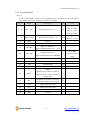
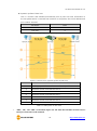
1.5.2 Pin assignment
⚫ JP1
JP1 is a user interface which is not populated by any connecters to be connected to
user device with user’s connector. The pitch is 2.54mm.
Pin #
Name
Description
I/O
Note
1 ~ 8
DI0 ~ DI7
Digital Input Port #0 ~ 7
In
Min VIL= -0.3V
Max VIL= 0.8V
Min VIH= 2.0V
Max VIH= 5.5V
9 ~ 16
DO0 ~ DO7
Digital Output Port #0 ~ 7
Out
Min VOH = 2.9V,
Max VOL = 0.4V
17
GND
Ground
−
18
GND
Ground
−
19
ADVREF
ADC VCC Reference
(Input Voltage Range: 2.6V ~ 3.3V)
In
20
ADC_IN0
Analog Input Port 0
(Input Voltage Range: 0V~ADVREF)
In
10-bit ADC
Conversion Time:
2.33㎲
21
RXD
Receive Data
In
22
CTS
Clear To Send
In
23
TXD
Transmit Data
Out
24
RTS
Request To Send
Out
25
RESET-
Reset
(Please set this value to 200us or
higher values for correct operation,
Active Low)
In
26
ISP-
ISP Mode: Low when it boots up
(Internally pulled-up, Active Low)
In
27
VCC
Power input (DC 3.3V)
−
28
VCC
Power input (DC 3.3V)
−
29
GND
Ground
−
30
GND
Ground
−
Table 1-3 JP1 pin assignment

CIE-M10 User Manual Ver. 3.4
- 12 -
https://www.ezTCP.com
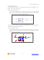
1.5.3 Digital Input Ports
CIE-M10’s digital input ports can be applied variously with circuit configuration – for
example: Wet contact and Dry contact.
⚫ Wet contact (voltage input)
This circuit gets voltage from the two input lines and convert it into logical levels (0
and 1). Then, it uses the value as a digital input. The following is a circuit example
with a photo-coupler which isolates circuits electrically.
Figure 1-9 a circuit of the input port
The [INPUT 1] and [INPUT 2] ports are user interface port. The working voltage is
concluded by the photo-coupler and resistors.
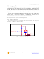
⚫ Dry contact (switch input)
This type needs an additional DC power source and the power source should be
isolated from the main DC power source of CIE-M10. In the figure below, input ports
need just a switch as the input.
Figure 1-10 a circuit of the output port
CIE_M10_DI
INPUT_A
1K(1/4W)
DC PWR
INVERTER
1 2
INPUT_B
3.3V
1K(1/4W)

CIE-M10 User Manual Ver. 3.4
- 13 -
https://www.ezTCP.com
1.5.4 Analog Input Port
There is an analog input port in CIE-M10. This port is connected to 10 bits ADC (Analog
to Digital Converter). User should input 2.6V~3.3V to the ADVREF for reference voltage of
the ADC. ADC_IN0 port is for user’s analog sensors, its input voltage should be between 0V
~ ADVREF. The ADC converts the input voltage of the ADC_IN0 (0V~ADVREF) to 0~1023
digital value.
User can read this value through Modbus/TCP and HTTP. User can read the ADC value
from the address of (Digital Input Port Address + 4) via Modbus/TCP. When user read the
ADC value via a web browser, user can read this value with $a0 variable.
All the input ports are only for the monitoring devices.
1.5.5 Digital Output Ports
The digital output ports can be interfaced with relays or SSR(Solid-State Relay). The
following is an example to interface to relays.
Figure 1-11 a circuit of the output port
OUTPUT_2
OUTPUT_1
VCC
CIE_M10_DO

CIE-M10 User Manual Ver. 3.4
- 14 -
https://www.ezTCP.com
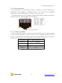
1.5.6 Ethernet Interface
An RJ45 connector is for the network interface of CIE-M10. You can use a UTP cable. It
automatically senses 10Mbits or 100Mbits Ethernet. It also provides auto MDI/MDIX
function that can automatically sense a 1:1 cable or cross over cable.
Each Ethernet device has its own hardware address (MAC address). CIE-M10 is shipped to
the market with the hardware address set in the factory.
Figure 1-12 the RJ45 connector
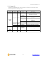
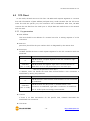
1.5.7 RS232 Port (DB9M)
There is a UART port which is 3.3V level. This port provides serial to TCP/IP converting
function working independently with its I/O ports. This port supports RTS/CTS flow control
function. The RTS informs to the counter part that its receiving buffer is free and is ready to
get data. And CIE-M10 gets CTS information from the counter part’s RTS.
Parameters
Supported Values
Baud rate
300 ~ 230,400 bps
Data bits
8, 7, 6, 5
Parity
None, Even, Odd, Mark, Space
Stop bit
1, 1.5, 2
Table 1-4 supported values of the RS232 port

CIE-M10 User Manual Ver. 3.4
- 15 -
https://www.ezTCP.com
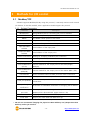
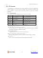
1.5.8 System LED
CIE-M10 has 4 LEDs(PWR, Do0, 2 LEDs on RJ45) to indicate the current system status.
Each LED represents the following status:
Mode
Name
Color
Status
Description
Common
PWR
Red
ON
Power is supplied
Normal
mode
STS_ACT
Yellow
Blinking every
second
Assigned an IP address
Blinking 4
times at once
Without being assigned an IP address
by DHCP
ON
Establishing a Modbus/TCP
connection
Blinking
Transferring data to the Ethernet
LINK_ACT
Green
ON
Connected with a network
Blinking
Receiving data from the Ethernet
Do0
Green
ON
When Do0 port’s signal is ON
Serial
Configuration
mode
STS_ACT
Yellow
Blinking
simultaneously
Under the serial configuration mode
ISP mode
STS_ACT
Yellow
OFF
Under the ISP mode
Table 1-5 system LED

CIE-M10 User Manual Ver. 3.4
- 16 -
https://www.ezTCP.com
2 Installation and Test
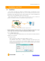
2.1 Installation
In this section, we explain the operation of CIE-M10 through a test. Basically, its input
and output ports are independently used. Thus, you can use either the input ports only for
monitoring or the output ports only for control. However, you can also correlatively use
those ports by using the MACRO mode on the output ports.
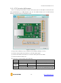
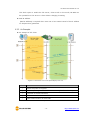
Before testing CIE-M10, you should connect the Ethernet port to a PC. It will be no
problem if the Ethernet connection is established through network hubs.
Figure 2-1 the connection between CIE-M10 and a PC
Because CIE-M10 is a type of module, you might need designing a board for it. If you
cannot design the board, please consider using external product, CIE-M10.
2.1.1 Setting Network Aera
This step is for setting both CIE-M10 and your PC to be located on the same network to
establish a TCP connection.
⚫ Setting of the PC
Add or change the IP address of the network adapter on your PC.
Click [Windows Control Panel] >> [Network Connections] and right click of your
mouse to get into [Properties of the Network Adapter], then you will see the
properties of [Internet Protocol (TCP/IP)]. Press the [Advanced Menu] button and add
an IP Address as shown below.
Figure 2-2 adding / changing an IP address

CIE-M10 User Manual Ver. 3.4
- 17 -
https://www.ezTCP.com
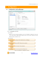
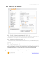
⚫ Setting of CIE-M10
ezManager is the management tool for setting parameters of CIE-M10. This
application is only for MS Windows and this is comfortable to use because it does
not need installation processes.
First, search your CIE-M10 via network. All the values of parameters are set to the
default values in the factory. To apply it to your system, proper values should be set
via ezManager.
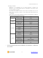
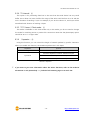
Default values of some major parameters are listed on the table below. To make the
test simple, keep these values during the test.
parameter
value
Network
Local IP Address
10.1.0.1
Subnet Mask
255.0.0.0
Option
Telnet
Checked
IP Address Search
Checked
Serial Port
Serial Type
RS232
Baud Rate
19,200bps
Parity
NONE
Data Bits
8
Stop Bit
1
Flow
NONE
Communication Mode
T2S – TCP Server
Local Port
1470
I/O Port
Web (HTTP)
Checked
Web (HTTP) Port
80
Modbus/TCP
Checked
Master/Slave
Slave
Connection Mode
Passive Connection
Multiple Connection
1
Local Port
502
Table 2-1 default values of some major parameters
You can download the latest version of ezManager on the [Download] >> [Utility] page
on our website.

CIE-M10 User Manual Ver. 3.4
- 18 -
https://www.ezTCP.com
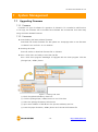
2.2 Test operation
2.2.1 Modbus/TCP Test
This is for checking the operation of Input and output ports of CIE-M10 via Modbus/TCP.
In this instruction, Modbus/TCP test program was used.
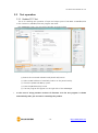
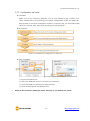
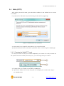
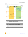
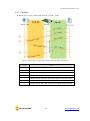
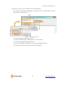
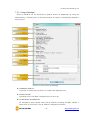
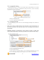
Run ezManager. Then, you can see the window as shown below.
Figure 2-3 Modbus/TCP test program of the ezManager
① Search the connected CIE-M10 with [Search All] button.
② Select a MAC address of searched product on the [search result].
③ Check the [Advanced Menu] option.
④ Press the [Modbus/TCP] button.
⑤ The test program will appear on the right side of the ezManager
In the case of using previous versions of firmware 3.1F the test program is shown
automatically when you succeed in searching the product.

CIE-M10 User Manual Ver. 3.4
- 19 -
https://www.ezTCP.com
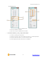
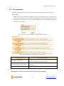
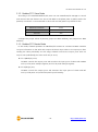
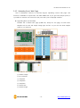
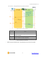
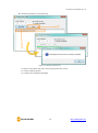
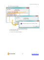
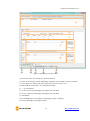
⚫ Modbus/TCP test
Figure 2-4 Modbus/TCP test
① Input the IP address of CIE-M10
② Input the local port for Modbus/TCP of CIE-M10
In a local area network, ① and ② steps can be omitted.
③ Connect by pressing [Connect] button
④ Under the connection, check if the Di LEDs are turned on or off with signal input
⑤ Check if Do LEDs are turned on or off with clicking the LEDs
⑥ Click the [Disconnect] button after the test is completed
La page est en cours de chargement...
La page est en cours de chargement...
La page est en cours de chargement...
La page est en cours de chargement...
La page est en cours de chargement...
La page est en cours de chargement...
La page est en cours de chargement...
La page est en cours de chargement...
La page est en cours de chargement...
La page est en cours de chargement...
La page est en cours de chargement...
La page est en cours de chargement...
La page est en cours de chargement...
La page est en cours de chargement...
La page est en cours de chargement...
La page est en cours de chargement...
La page est en cours de chargement...
La page est en cours de chargement...
La page est en cours de chargement...
La page est en cours de chargement...
La page est en cours de chargement...
La page est en cours de chargement...
La page est en cours de chargement...
La page est en cours de chargement...
La page est en cours de chargement...
La page est en cours de chargement...
La page est en cours de chargement...
La page est en cours de chargement...
La page est en cours de chargement...
La page est en cours de chargement...
La page est en cours de chargement...
La page est en cours de chargement...
La page est en cours de chargement...
La page est en cours de chargement...
La page est en cours de chargement...
La page est en cours de chargement...
La page est en cours de chargement...
La page est en cours de chargement...
La page est en cours de chargement...
La page est en cours de chargement...
La page est en cours de chargement...
La page est en cours de chargement...
La page est en cours de chargement...
La page est en cours de chargement...
La page est en cours de chargement...
La page est en cours de chargement...
La page est en cours de chargement...
La page est en cours de chargement...
La page est en cours de chargement...
La page est en cours de chargement...
-
 1
1
-
 2
2
-
 3
3
-
 4
4
-
 5
5
-
 6
6
-
 7
7
-
 8
8
-
 9
9
-
 10
10
-
 11
11
-
 12
12
-
 13
13
-
 14
14
-
 15
15
-
 16
16
-
 17
17
-
 18
18
-
 19
19
-
 20
20
-
 21
21
-
 22
22
-
 23
23
-
 24
24
-
 25
25
-
 26
26
-
 27
27
-
 28
28
-
 29
29
-
 30
30
-
 31
31
-
 32
32
-
 33
33
-
 34
34
-
 35
35
-
 36
36
-
 37
37
-
 38
38
-
 39
39
-
 40
40
-
 41
41
-
 42
42
-
 43
43
-
 44
44
-
 45
45
-
 46
46
-
 47
47
-
 48
48
-
 49
49
-
 50
50
-
 51
51
-
 52
52
-
 53
53
-
 54
54
-
 55
55
-
 56
56
-
 57
57
-
 58
58
-
 59
59
-
 60
60
-
 61
61
-
 62
62
-
 63
63
-
 64
64
-
 65
65
-
 66
66
-
 67
67
-
 68
68
-
 69
69
-
 70
70


Sollae Systems CIE-M10 Manuel utilisateur
- Taper
- Manuel utilisateur
dans d''autres langues
- English: Sollae Systems CIE-M10 User manual