
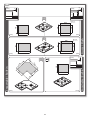
taste of design
T
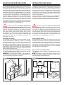
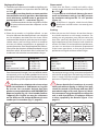
ables de cuisson Select Plus / Unique / Wolo
Selec
t / Unique / Wolo Hobs
Manuel d’installation et d’emploi
Installation and use manual
1PSP0604#00--
1PSPF0604#00--
1PSP0603T#00--
PSP0603T#00--
1PSP0704T#00--
1PSPF0704T#00--
PSP0704T#00--
1PSP0904T#00--
1PSPF0904T#00--
PSP0904T#00--
1PSP1004T#00--
1PSPF1004T#00--
PSP1004T#00--
1PSP1203T#00--
PSP1203T#00--
1PSPA904T#00--
1PUN0603T#00--1
1PSU0603T#00--
1PUN0704T#00--1
1PSU0704T#00--
1PUN0904T#00--1
1PSU0904T#00--
1PUN1004T#00--1
1PSU1004T#00--
1PUN1203T#00--1
1PSU1203T#00--
PIWL40ZI

2
Tous nos compliments pour votre achat d’un
produit Barazza !
Cet appareil de haute qualité vous accompagnera
longtemps en cuisine en vous offrant d’excellentes
prestations de manière sûre et fiable.
L’installation et l’utilisation de l’appareil sont simples
et rapides.
Nous vous prions de lire attentivement ce manuel
pour réaliser la bonne installation et la bonne utilisa-
tion de l’appareil, et pour le maintenir un bon état de
fonctionnement.
Les symboles suivants permettent de faciliter la lec-
ture du manuel :
Prescriptions importantes sur la sécurité
individuelle et sur celle de l’appareil
Informations générales
Congratulations on purchasing a Barazza ap-
pliance!
This safe and reliable high-quality appliance can assist
you in your work with long-lasting top-level perform-
ance.
It also has the added advantage of being quick and
simple to install and easy to use.
Please read this manual carefully, as it provides im-
portant information for the correct installation and
use of the appliance which will ensure its long-term
efficiency.
The following symbols are used to assist you in reading
this manual:
Important rules for personal safety and the
safety of the appliance
General information
Le fabricant se réserve le droit d’apporter, sans préavis,
toutes les modications qu’il jugera utiles à ses produits. Les
dessins, les schémas d’installation et les tableaux contenus dans
ce manuel sont fournis à titre indicatif.
Les installations de branchement de l’édifice doivent être
conformes aux normes nationales en vigueur.
Il est interdit de copier et/ou de reproduire, même partiellement,
les contenus du présent manuel, et/ou de les divulguer à des tiers
sans l’autorisation du fabricant.
Cet appareil est conforme aux prescriptions des directives euro-
péennes 2014/35/UE pour la basse tension, 2014/30/UE pour
la compatibilité électromagnétique et de la règlementation
européenne 2016/426 pour le gaz.
Les instructions de ce livret sont valables seulement pour le pays
de destination.
The manufacturer reserves the right to make any changes
deemed suitable to the product without prior notice.
The drawings, installation diagrams and tables contained in this
manual are approximate and for informational purposes only.
The systems for connecting the appliance must comply with current
national regulations.
The partial or complete reproduction or photocopying of the contents
of this manual IS forbidden, as well as the sending of this manual to
third parties, without the Manufacturer’s permission.
This appliance is compliant with the EU Low Voltage Directive
2014/35/EU, Electromagnetic Compatibility Directive 2014/30/EU
and Gas Appliances Regulation 2016/426.
The instructions in this booklet are valid only for the country of
destination.

3
INDEX INDEX
DESCRIPTION PAGE
CARACTÉRISTIQUES TECHNIQUES 4
INSTALLATION 7
Consignes de sécurité 7
Contrôle et mise en place 8
Élimination de l'emballage 8
Choix du lieu d'installation 9
Branchement électrique 10
Raccordement au gaz 12
Réglage du minimum 14
Adaptation à d'autres types de gaz 15
Installation de l'appareil encastrable 16
UTILISATION 19
Consignes de sécurité 19
Avant de commencer 21
Connaître l’appareil 21
Bandeau de commande 22
Bon à savoir 24
Utilisation de l'appareil 25
Utilisation des brûleurs 25
Mauvais fonctionnement 27
Accessoires 27
ENTRETIEN 28
Consignes de sécurité 28
Entretien ordinaire 29
Nettoyage 29
Périodes d'inutilisation 30
Élimination 31
Service après-vente 31
DESCRIPTION PAGE
TECHNICAL DATA 4
INSTALLATION 7
Safety warnings 7
Checks and handling 8
Disposal of the packaging 8
Installation site choice 9
Connection to the power mains 10
Gas connection 12
Regulating the minimum 14
Gas conversion 15
Built-in unit installation 16
USAGE 19
Safety warnings 19
Before starting 21
Understanding the appliance 21
Control panel 22
Useful information 24
Using the appliance 25
Using the burners 25
Abnormal operation 27
Accessories 27
MAINTENANCE 28
Safety warnings 28
Maintenance schedule 29
Cleaning 29
Periods of inactivity 30
End-of-life disposal 31
After-sales service 31

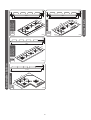
CARACTÉRISTIQUES TECHNIQUES TECHNICAL DATA
Insulating
class
1
1
L=90cm
Les dimensions d’encombrement peuvent être dif-
férentes pour les appareils fabriqués hors standard.
With custom made models, dimensions vary.
1PSP0604#00--
1PSP0603T#00--
1PUN0603T#00--1
1PSU0603T#00--
1PSPF0604#00--
PIWL40ZI
1PSP0704T#00--
1PUN0704T#00--1
1PSU0704T#00--
1PSPF0704T#00--
1PSP0904T#00--
1PUN0904T#00--1
1PSU0904T#00--
1PSPF0904T#00--
60
60
60
60
[mm]
[mm]
[mm]
553
45
3
3
46
45 46
500 / 510
585
60
60
[mm]
553
46 46
500
585
70
70
90
90
500 / 510
700
[mm]
510
585
[mm]
70
70
500
700
500 / 510
86
0
832
90
90
R=6
18 27
674
550
45
3
46
18 28
674
550
46
1,5
1,5
46
R=6
553
41
11
46
500
860
R=6
46 46
830
1,5
Encastrable / Built-in
Au ras / Flush

5
1PSP1004T#00--
1PUN1004T#00--1
1PSU1004T#00--
1PSP1203T#00--
1PUN1203T#00--1
1PSU1203T#00--
1PSPF1004T#00--
45 46
3
100
100
120
120
[mm]
[mm]
450
1000
350
1160
850
970
18 27
46 46
1,5
850
970
18 28
45 46
1120
100
100
[mm]
450
1000
R=6
1PSPA904T#00--
45
3
46
[mm]
A
A
500
830
1130
Encastrable / Built-in
Au ras / Flush

6
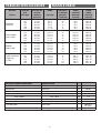
Caractéristiques techniques Technical data
Tension Voltage V 220-240
Fréquence Frequency Hz 50/60
Puissance brûleurs Burner power
auxiliaire auxiliary kW 1
semi-rapide semi- rapid kW 1,75
rapide rapid kW 3
triple couronne triple ring kW 3,8
Type de câble Cable type
H05RR-F
3x1 mm
2
Longueur câble Cable length cm 90
TABLEAU DES GICLEURS NOZZLE TABLE
Brûleur
Burner
Type de
gaz
Gas type
Pression de
service
Applied
pressure
Débit
Capacity
ø Gicleurs
1/100 mm
ø Nozzles
1/100 mm
Débit
nominal
Nominal
capacity
Débit
réduit
Reduced
capacity
Auxiliaire
Auxiliary
G30
G31
G30
G31
G20
G25
30 mbar
37 mbar
50 mbar
50 mbar
20 mbar
25 mbar
g/h 73
g/h 73
g/h 73
g/h 73
l/h 94
l/h 110
50
50
43
43
71
72
kW 1
kW 1
kW 1
kW 1
kW 1
kW 1
kW 0.45
kW 0.45
kW 0.45
kW 0.45
kW 0.45
kW 0.45
Semi-rapide
Semi- rapid
G30
G31
G30
G31
G20
G25
30 mbar
37 mbar
50 mbar
50 mbar
20 mbar
25 mbar
g/h 127
g/h 127
g/h 127
g/h 127
l/h 158
l/h 165
65
65
58
58
96
94
kW 1.75
kW 1.75
kW 1.75
kW 1.75
kW 1.75
kW 1.75
kW 0.45
kW 0.45
kW 0.45
kW 0.45
kW 0.45
kW 0.45
Rapide
Rapid 3 kW
G30
G31
G30
G31
G20
G25
30 mbar
37 mbar
50 mbar
50 mbar
20 mbar
25 mbar
g/h 218
g/h 218
g/h 218
g/h 218
l/h 270
l/h 292
85
85
75
75
115
121
kW 3
kW 3
kW 3
kW 3
kW 3
kW 3
kW 0.85
kW 0.85
kW 0.85
kW 0.85
kW 0.85
kW 0.85
Triple couronne
Triple ring
3,8 kW
G30
G31
G30
G31
G20
G25
30 mbar
37 mbar
50 mbar
50 mbar
20 mbar
25 mbar
g/h 276
g/h 276
g/h 276
g/h 276
l/h 358
l/h 411
98
98
77
77
133
143
kW 3.8
kW 3.8
kW 3.8
kW 3.8
kW 3.8
kW 3.8
kW 1.40
kW 1.40
kW 1.40
kW 1.40
kW 1.40
kW 1.40

7
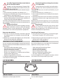
SAFETY WARNINGS
Read this instruction booklet carefully before instal-
lation and/or use of the appliance and keep it handy
so that all the users can consult it; if you give away or sell
the appliance, please ensure that you give this booklet
to the new user so that he can be informed about its
installation, use and safety rules.
The installation and any interventions on the ap-
pliance (special maintenance, nozzle replacement, idle
mode setting, etc.) must be carried out by authorised
personnel only, as specified in this booklet.
The connection systems (gas and electric) and installa-
tion rooms must be suitable and satisfy the safety stand-
ards in force in the country of use (protective isolating
switch, earthing system, equipotential system, etc.).
The manufacturer will not be held liable if the above
requirements are not satisfied.
During installation, maintenance or repair work,
always switch off the main electrical switch, remove the
connection plug from the socket and shut off the gas
supply taps.
The appliance is not designed for outdoor use.
Appliances may have sharp edges; handle them
with caution and use personal safety equipment (protec-
tive shoes, safety gloves, etc.).
INSTALLATION INSTALLATION
CONSIGNES DE SÉCURITÉ
Lire attentivement le manuel d’emploi avant
l’installation et/ou l’utilisation de l’appareil et le
ranger dans un lieu accessible à tous les utilisateurs
pour permettre toute consultation ultérieure; en
cas de cession ou de vente de l’appareil, veiller à
bien remettre ce manuel au nouvel utilisateur pour
l’informer sur l’installation, sur l’utilisation et sur les
consignes de sécurité de l’appareil.
L’installation et les interventions sur l’appareil
(entretien extraordinaire, remplacement des gicleurs,
réglage du minimum, etc..) ne doivent être effectuées
que par du personnel qualifié conformément aux
indications contenues dans le manuel.
Les installations de branchement (gaz et électricité)
et les locaux doivent être conformes aux normes de
sécurité en vigueur dans le pays d’installation de
l’appareil (interrupteur de protection et disjoncteur,
installation de mise à la terre, équipotentiel, etc.).
Le fabricant décline toute responsabilité en cas de
non-respect des prescriptions.
Pendant les opérations d’installation, d’entre-
tien ou de réparation, éteindre toujours l’interrupteur
électrique principal, débrancher la prise de courant et
fermer les robinets d’alimentation du gaz.
L’appareil n’est pas conçu pour une utilisation
en plein air.
Le bord des appareils pouvant résulter par-
ticulièrement coupant, il faut les manipuler avec
précaution et en utilisant des équipements de protec-
tion individuelle appropriés (chaussures de sécurité,
gants, etc...).

8
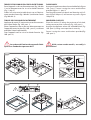
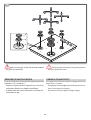
CHECKS AND HANDLING
After having unpacked the appliance and removed all
the packing materials and protective films from the sur-
faces, check for any anomalies: if you find an anomaly,
do not proceed with the installation but contact your
retailer within 8 days, reporting the data provided on
the appliance’s data plate and describing the problems
(fig.1).
Attention! Do not leave the packing materials (plas-
tic bags, polystyrene, etc.) unattended, as they are a
potential hazard for children and animals (danger
of suffocation).
Move the appliance to the installation location using
appropriate personal safety equipment (figure 1) and
adopting all the precautions necessary to prevent dam-
age to the appliance, people, animals and property.
DISPOSAL OF THE PACKAGING
Attention! Dispose of the packaging in compliance
with current regulations in the country where the
appliance is installed.
Package composition:
- cardboard
- polyethylene / polypropylene: outer packaging film,
instructions bag
- expanded polystyrene: impact protections.
CONTRÔLE ET MISE EN PLACE
Après avoir déballé l’appareil et avoir retiré le matériel
d’emballage et les pellicules de protection des sur-
faces, contrôler l’absence de défauts apparents : en cas
de vices, ne pas installer l’appareil, mais contacter le
revendeur dans les 8 jours suivant la réception, et lui
communiquer les données indiquées sur la plaque de
matricule de l’appareil et les problèmes constatés
(fig. 1).
Attention ! Ne pas laisser le matériel d’emballage
sans surveillance (sachets, polystyrène, etc...) car
il constitue un risque potentiel de danger pour les
enfants et les animaux (danger d’étouffement).
Dûment muni d’équipements de protection indivi-
duelle, transporter l’appareil sur le lieu d’installation
(fig. 1) et en prenant toutes les précautions nécessaires
pour ne causer aucun dommage à l’appareil, aux
biens, aux personnes ou aux animaux.
OK!
1
ÉLIMINATION DE L’EMBALLAGE
Attention ! Éliminer les pièces d’emballage confor-
mément aux normes en vigueur dans le pays
d’installation.
Composition de l’emballage :
- carton
- polyéthylène/polypropylène : pellicule externe,
sachet du manuel d’emploi
- polystyrène expansé : protections anti-choc.

9
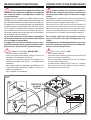
CHOIX DU LIEU D’INSTALLATION
Caractéristiques du lieu d’installation
Les appareils doivent être installés dans des locaux appro-
priés, ayant une température maximale de 25 °C et un taux
d’humidité maximum de 60% ; les locaux doivent répondre
aux normes de sécurité en vigueur dans le pays d’installation
de l’appareil (interrupteur de protection et disjoncteur, ins-
tallation de mise à la terre, équipotentiel, etc.). Les appareils
ne sont pas adaptés à l’installation en plein air ni à l’expo-
sition aux agents atmosphériques et aux intempéries. Les
appareils peuvent être montés sur des meubles fabriqués
avec des matériaux résistants à la chaleur. Une table de
cuisson encastrée au ras du plan de travail n’est adaptée
qu’aux bases en pierre naturelle (granit, marbre), bois massif
et carrelées. Pour les plans de travail dans d’autres matériaux,
demander au fabricant s’ils sont adaptés à l’encastrement de
tables de cuisson au ras du plan de travail.
Les locaux d’installation doivent disposer d’un
système de renouvellement d’air continu pour permettre
l’arrivée constante de l’air nécessaire à la combustion du gaz,
selon les dispositions prévues par les normes en vigueur
UNI – CIG 7129 et 7131.
Des ouvertures d’une section
d’au moins 100 cm
2
doivent être réalisées près du sol et
de manière à ne pouvoir être obstruées ni de l’intérieur ni
de l’extérieur
(fig. 2). Toute autre forme de ventilation doit
nécessairement répondre aux dispositions prévues par la
norme UNI – CIG 7129.
Évacuation des fumées
Les appareils à gaz doivent évacuer les produits de com-
bustion directement à l’extérieur à travers des conduits
de fumée, moyennant des hottes d’aspiration ou des
électroventilateurs (UNI – CIG 7129) (
fig. 2) de débit tel à
permettre un renouvellement d’air par heure d’au moins 3
fois le volume du local. Nous rappelons que le volume d’air
nécessaire à la combustion est de 2 m
3
/h pour chaque kW de
débit calorifique nominal (se référer à la plaque de matricule
pour le débit calorifique total).
Distance par rapport au mur postérieur et aux murs latéraux
Les appareils doivent être installés en respectant certaines
distances par rapport aux murs (
fig. 3).
REMARQUE :
Si une hotte est installée sur la table de cuis-
son, consulter les instructions de montage de la hotte pour
connaître la distance correcte à respecter.
9
AIR
AIR
AIR
min. 60 cm
2
INSTALLATION SITE CHOICE
Installation site characteristics
The appliances must be placed in suitable interior locations with
a maximum temperature of 25°C and maximum humidity of
60%; the locations must satisfy the safety standards in force in
the country of use (protective isolating switch, earthing system,
equipotential system, etc.). The appliances are not designed
for outdoor use, to be exposed to the elements or bad weather
conditions. Appliances may be assembled onto units made of
heat-resistant materials .
A built-in hob, flush with the worktop, is only suitable with
natural stone (granite, marble), solid wood and tiled bases.
In the instance of bases made from other materials, please ask
the manufacturer whether they are suitable for flush hobs.
Installation locations must have continuous
air exchange to provide the air flow necessary for gas
combustion as specified in the standards in force UNI – CIG
7129 and 7131. Openings with an area of at least 100 cm
2
must be constructed in such a way so that they cannot be
obstructed from neither the inside or the outside and they
must be positioned in proximity to the ground (
figure 2).
Every other ventilation type must be in accordance with
specifications in the standard UNI – CIG 7129.
Fume discharge outlet
Gas appliances must release the combustion emissions
directly outside via flues, either by using extractor hoods or
electric fans (UNI – CIG 7129) (
figure 2) with sufficient power
to guarantee hourly air exchange at least 3 times the loca-
tion volume. It is to be noted that 2m
3
/h of air is necessary
for every kW of nominal thermal capacity (consult the data
plate for total thermal capacity).
Distance from side and back walls
The appliances must be kept at a specified distance from
walls (
figure 3).
NOTE: If installing a range hood above the hob be sure
to follow the hood assembly instructions and the correct
mounting height contained therein.
min. 65 cm
min. 45 cm
A
B
A B
60 5 2
70 5 10
90 5 2
100 5 10
116 5 2
Angulaires
/Corner
5 5
xx
xx
[cm]
3

10
CONNECTION TO THE POWER MAINS
Before making the connection, make cer-
tain that the voltage and frequency indicated on
the data plate match those of the power supply
system.
The appliance is supplied with a 90cm-long power cord
(H05RR-F) on which a 10 A plug must be installed to then
be connected with a power outlet
(figure 4a).
Alternatively, the cable can be connected directly to
the distribution network (figure 4b): in this case an om-
nipolar disconnecting switch must be provided, with a
minimum opening of the contacts that allows complete
disconnection in category III overvoltage conditions.
The isolating switch must be located in a position
which is accessible even after the appliance is in
-
stalled.
If the appliance is installed together with an oven, the
connection of the two appliances must be independ
-
ent for electrical safety reasons.
The power cord must NOT:
- be crushed or rolled up;
- come into contact with any type of liquid, sharp or hot
objects or corrosive substances;
- reach, at any point, a temperature which is 50°C higher
than the room temperature;
- be replaced with a different type of cable (see “Technical
data” on p. 4)
or with a cable which is not up to standard;
- be lengthened with extensions.
BRANCHEMENT ÉLECTRIQUE
Avant de brancher l’appareil, vérifier que
la tension et la fréquence indiquées sur la plaque
des caractéristiques correspondent à celles du
réseau électrique.
L’appareil livré est équipé d’un câble d’alimentation
(H05RR-F) de 90 cm de long auquel il faudra installer une
prise de 10 A à brancher sur une prise de courant
(fig. 4a).
En alternative, il est possible de brancher directement
le câble au réseau d’alimentation (fig. 4b) : dans ce cas,
il faut installer un dispositif de coupure omnipolaire
avec une distance d’ouverture des contacts en mesure
de couper entièrement le courant dans les conditions
de la catégorie de surtension III.
La prise de courant et l’interrupteur omnipolaire
doivent être conformes et rester accessibles même
en cas d’appareil encastrable.
Si l’appareil est installé en combinaison à un four,
le branchement des deux appareils doit être indé
-
pendant pour des motifs de sécurité électrique.
Le câble d’alimentation NE DOIT PAS:
- résulter écrasé ou entortillé ;
- entrer au contact de liquides, d’objets chauds ou
coupants, de substances corrosives ;
- atteindre, en quelque point de sa longueur, une
température dépassant de 50 °C la température
ambiante ;
- être remplacé par un câble de type différent
(voir
“Caractéristiques techniques” page 4)
ou par un
câble non conforme ;
- être raccordé à une rallonge.
10
H05V2V2-F
3x1mm
2
90 cm
10A
B
A
G30 - 28 mbar
220V-240V 50HZ
0,000 Kw
G20 - 20 mbar
Questo apparecchio deve essere installato conformemente alle norme in
vigore e utilizzato solamente in locale ben areato. Consultare il libretto
istruzioni
p
rima di installare e usare l'a
p
arecchio.
REGOLATO A
GAS
G20
N°: XXXXXXXXX
CATEGORIA II 2H3+ IT
F.lli BARAZZA s.r.l.
MADE IN ITALY
Qn
g/h
00.0 kW
000
g/h
XXXXX
XXXXX
XXXXX
MOD
ART
N°
istruzioni
prima
di
installare
e
usare
l aparecchio
.
4

11
REMPLACEMENT DU CÂBLE D’ALIMENTATION
Si nécessaire, le câble d’alimentation devra
être remplacé par un câble de type identique
(voir
“Données techniques” page 4)
en conformité aux
normes en vigueur dans le pays d’installation.
Si l’appareil est déjà branché, le débran-
cher de l’alimentation électrique et fermer les
robinets d’arrêt du gaz.
Pour accéder aux branchements électriques, retirer
le petit couvercle du bornier en dévissant la vis de
blocage
(fig. 5).
Détacher le vieux câble du bornier et le retirer; bran-
cher le nouveau câble (uniquement de type H05RR-F)
aux bornes correspondantes N - L - Terre.
Bloquer le nouveau câble avec le serre-câble prévu
à cet effet, puis refermer le bornier en revissant le
couvercle.
N
L
5
POWER CORD REPLACEMENT
If necessary, the power cord can be replaced
with an identical type
(see “Technical data” on page
4).
in compliance with current regulations in the
country where the appliance is installed.
If the appliance is already connected,
disconnect the electrical power and shut off gas
supply taps.
To access the electrical connections, remove the cover
from the terminal board by unscrewing the screws
(figure 5).
Disconnect the old cord from the terminals and remove
it; connect the new cord (only the H05RR-F type) into the
respective terminals N - L - Earth.
Cover the new cord with the appropriate cord holder and
re-close the terminal, replacing its cover.

12
RACCORDEMENT AU GAZ
Avant d’effectuer le raccordement, vérifier
que toute l’installation de gaz ainsi que les locaux
d’installation soient conformes aux normes en
vigueur dans le pays d’installation (UNI-CIG 7129
e 7131).
- Vérifier que la ligne d’alimentation ne soit point
obstruée et que son débit soit suffisant pour assurer
le bon fonctionnement de l’appareil.
- Vérifier qu’un robinet d’arrêt du gaz soit installé sur
la ligne d’alimentation en une position accessible
et facile à contrôler : ce robinet devra être fermé
pendant les opérations d’installation et d’entretien
de l’appareil
-
Contrôler le type de gaz qui alimentera l’appareil (Gaz
liquide G30/G31 ou Méthane G20/25) et contrôler
que l’appareil soit prédisposé pour ce type d’ali-
mentation : en cas contraire, l’adapter en suivant les
indications du paragraphe
“Adaptation à d’autres
types de gaz” page 15
.
- Procéder au raccordement : (fig. 6) le raccord coudé
en “L” (filetage GJ ½”) monté sur la rampe d’alimen-
tation “A” permet d’effectuer le raccordement au
réseau d’alimentation avec un tuyau rigide (norme
UNI-CIG 7129) ou avec un tuyau flexible en acier
inox à gaine continue (norme UNI-CIG 9891).
Le raccord au tuyau rigide ou flexible doit garantir
l’étanchéité moyennant le joint “G2”.
Le raccord coudé en “L” peut être orienté en
desserrant l’écrou “B”; le rebloquer une fois
l’opération terminée. L’étanchéité est garan-
tie par la forme particulière de la rampe et par le
joint interne.
A
L
(GJ ½)
B
G2
UNI-CIG 9891
UNI-CIG 7129
6
GAS CONNECTION
Before connecting the appliance, ensure that
the gas system and the installation locations comply
with current regulations in the country where the
appliance is installed (UNI-CIG 7129 and 7131).
- Ensure that the supply line is not obstructed and has
sufficient power to ensure correct operation of the
appliance.
- Ensure that the supply line, which should be located
in an easily accessible and visible location, has a gas
shut-off valve: this should be closed during appliance
installation and maintenance operations.
-
Check the gas type which will power the appliance
(Liquid Gas G30/G31 or Methane G20/25) and ensure
that the appliance is compatible with this: in the case
where it is not compatible, adapt it as instructed in the
paragraph “Adaptation to other gas types” on page
15
.
- Proceed with connecting the appliance: (figure 6)
an L-shaped rubber connector (thread GJ ½”) is as-
sembled to power ramp “A”; this ensures connection
to the distribution network via a solid pipe (standard
UNI-CIG 7129) or a flexible stainless steel pipe flush
with the wall (standard UNI-CIG 9891).
Connection to the solid or flexible pipe is guaranteed
by using sealant “G2” to secure attachment.
The L-shaped connector can be positioned by
loosening the “B” nut and then, once posi-
tioned, re-tightening the nut. The specific form
of the ramp and the inner sealant guarantee attach-
ment.

13
Si la pression du gaz est peu stable, installer
un régulateur de pression du gaz en amont de
l’appareil (si l’appareil doit fonctionner au gaz li-
quide (G30 ou G31), utiliser exclusivement un régu-
lateur de pression conforme à la norme UNI-CIG
7432 (30 mbars).
Une fois l’installation terminée, contrôler
que tous les raccords soient parfaitement étanches
en utilisant une solution d’eau et de savon. NE PAS
utiliser de flammes nues !
Une fois l’installation terminée, essayer
d’allumer tous les brûleurs (consulter la
page 25) et
contrôler que la flamme soit stable et régulière. Au
besoin, procéder au réglage du minimum comme
indiqué
page 14).
Le réglage terminé, l’installateur doit expliquer à
l’utilisateur le mode d’utilisation correct de l’appareil.
Si l’appareil ne devait pas fonctionner correctement
après tous les contrôles effectués, contacter le reven-
deur local agréé.
If the gas pressure is unstable and it runs on
liquid gas (G30 or G31), install, above the appliance,
a gas pressure regulator; only use a gas pressure
regulator which complies with the standard UNI-CIG
7432 (30 mbar).
Before Leaving: Check all connections for
gas leaks with soap and water. DO NOT use a naked
flame for detecting leaks.
Before Leaving: Ignite all burners to ensure
correct operation of gas valves, burners and ignition
(
consult page 25). Turn gas taps to low flame posi-
tion and observe stability of the flame, regulating
the minimum if necessary (consult page 14).
When satisfied with the hotplate, please instruct the
user on the correct method of operation. In case the
appliance fails to operate correctly after all checks have
been carried out, refer to the authorised service provider
in your area.
Problème : Solution
Le flux du gaz
semble irrégulier
• Contrôler que le robinet
de gaz soit complètement
ouvert.
• Contrôler que le réseau de
raccordement ait un débit
adéquat.
• Contrôler que les chapeaux
et les brûleurs soient placés
correctement et privés d'obs-
tructions.
• Contrôler que les gicleurs
soient adaptés au type de
gaz utilisé.
• Contrôler le bon étalonnage
du régulateur de pression, si
présent.
• Contrôler le tuyau d'alimen-
tation du gaz (tuyau obs-
trué, tuyau plié/écrasé, tuyau
excessivement long, tuyau
inadapté, etc...).
Problem: Solution
The gas flow
seems irregular
• Check that the gas tap is fully
open.
• Check that the connection net-
work has a sufficient supply.
• Check that the flame distribu-
tors and the burners are cor-
rectly positioned and that they
are not obstructed.
• Check that the nozzles are suit-
able for the gas type used.
• Check that the pressure regu-
lator is correctly calibrated.
• Check the gas supply pipe
(check that the pipe is not
obstructed, folded/crushed,
too long, unsuitable, etc...).

14
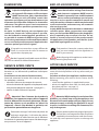
RÉGLAGE DU MINIMUM
Effectuer le réglage du minimum sur un
brûleur à la fois.
- Allumer un brûleur et mettre la manette sur la
position du minimum
.
- Extraire la manette correspondant au brûleur
allumé jusqu’à la retirer complètement (fig. 7 - dét.1)
; utiliser le tournevis fourni pour régler la vis située
à côté de l’axe de la manette (fig.7 - dét.2).
- Tourner la vis à droite pour diminuer la flamme
ou à gauche pourl’augmenter, jusqu’à obtenir le
minimum désiré.
En cas de fonctionnement à GPL Universel, la vis de
réglage du minimum devra être entièrement vissée.
- Remonter soigneusement les manettes en vérifiant
qu’elles soient placées correctement.
À la fin du réglage, vérifier :
1) l’absence de fuite de gaz et le bon fonctionne-
ment des brûleurs en utilisant une solution d’eau
et de savon. NE PAS utiliser de flammes nues !
2) que les brûleurs ne s’éteignent pas en tournant
rapidement les manettes de la position de maximum
à celle de minimum. S’il y a lieu, augmenter le débit
des minimums en intervenant sur la vis de réglage.
1
2
7
REGULATING THE MINIMUM
Adjust the low flame on each burner one
at a time.
- Switch on a burner and bring the knob to the mini-
mum setting
.
- Turn the knob regulating the relevant burner until the
knob completely comes away (figure 7 - parts 1); use
the provided screwdriver to set the screw at the side
of knob pivot (figure 7 - parts 2).
- Turn the screw towards the right to decrease the
flame or towards the left to increase the flame, in
order to ascertain the desired idle setting.
If powered by Universal LPG the adjustment screw
controlling the idle mode setting must be completely
screwed in.
- Replace the knobs with utmost care ensuring that you
have correctly positioned them.
Once you have completed the setting process,
check that:
1) there are no gas leaks and that the burners are
functioning correctly by using a mixture of water and
soap, NOT naked flames!
2) when rotating the knobs immediately from the
maximum to the minimum setting, that the burners
do not switch off. Increase the idle mode capacity
using the adjustment screws.

15
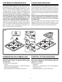
ADAPTATION À D’AUTRES TYPES DE GAZ
Retirer les grilles, les chapeaux et les brûleurs; retirer
les gicleurs avec la clé fournie en dotation
(fig. 8) et
les remplacer par ceux fournis en dotation, en res-
pectant scrupuleusement le repère et le tableau des
gicleurs
page 6.
En cas de réglage de l’appareil pour un type de gaz dif-
férent de celui prévu initialement, l’installateur devra
appliquer les deux étiquettes fournies en dotation sur
la plaque de matricule de l’appareil et sur la garantie
pour documenter et identifier le nouveau réglage.
3
1
2
8
GAS CONVERSION
Remove the racks, the flame distributors and the burners;
with the spanner provided, remove the nozzles
(figure 8)
and replace them with the provided nozzles, carefully
checking the identification mark and the nozzle table
on
page 6. In the case where you carry out an appliance
regulation operation for a gas type that differs from
the above mentioned, appended to the present docu-
mentation, you will find two new stickers which must
be attached to both the appliance data plate and the
Guarantee by the person responsible for installation; the
stickers recognise and document the new regulation.

16
INSTALLATION DE L’APPAREIL ENCASTRABLE
Vérifier le bon état et la stabilité du meuble
destiné à accueillir l’appareil (Norme DIN 68930).
Découper le plan de travail selon les mesures indiquées
fig. 9a-9b ; si l’appareil est encastré au-dessus d’un four, il
faut installer un panneau de séparation (B) à une distance
d’au moins 1 cm du fond de l’appareil, panneau qui devra
être perforé dans la partie postérieure pour le passage de
l’alimentation électrique de l’appareil (fig.10).
16
[mm]
[mm]
[mm]
[mm]
[mm] [mm]
90
90
100
100
120
120
840
480
980
430
1140
330
1,7
1,5
[mm]
3
[mm]
R=7,5
453
1003
980
430
R=7,5
353
1163
1140
330
R=7,5
503
863
840
480
9A
BUILTIN UNIT INSTALLATION
Make certain that the cabinet in which you
will be installing the appliance is in perfect condition
and completely stable (Standard DIN 68930).
Prepare an embedded hole with measurements as specified
in
figures 9A-9B; if the appliance is to be installed above an
oven, it is also necessary to provide an isolating panel (B) with
a distance of at least 1 cm from the base of the appliance; the
isolating panel must be placed under the appliance to allow for
the gas pipe and the appliance’s supply of electrical power.
Encastrable / Built-in
Au ras / Flush

17
[mm]
[mm]
[mm]
[mm]
1,7
60
60
70
70
1,5
[mm]
503
588
560
480
R=7,5
R=7,5
560
480
560
480
503
703
680
480
680
480
[mm]
[mm]
A
A
60
60
3
[mm]
11
[mm]
605
60
5
205
48
0
33
0
480
9B
Encastrable / Built-in
Encastrable / Built-in
Au ras / Flush

18
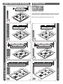
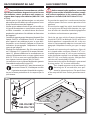
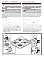
TABLES DE CUISSON AU RAS DU PLAN DE TRAVAIL
Poser l’appareil sur le trou d’encastrement
(fig. 10A dét.
1) en le bloquant avec les vis et les brides fournies
(fig. 11 dét. 2)
.
Sceller la fissure entre la table de cuisson et l’abaisse-
ment avec du silicone
(fig. 10A dét. 3)
et éliminer l’excès
(fig.10A dét. 4).
TABLES DE CUISSON À ENCASTREMENT
Appliquer le mastic (G) autour du trou en faisant atten-
tion à bien l’étaler (fig. 10B - part. 1).
Placer l’appareil au-dessus du trou d’encastrement en
l’appuyant contre le plan (fig. 10B - part. 2), en faisant
attention à bien le positionner.
Fixer l’appareil avec les vis et les brides fournies (fig.
10B - part. 3).
Le système de fixation des appareils fabri-
qués hors standard est personnalisé.
FLUSH PANELS
Arrange the appliance above the embedded hole (figure
10A - part 1) secure it using the screws and brackets
provided (figure 11 - part 2).
Seal the gap between the panel and lowering with sili-
cone (figure 10A part 3) and remove any excess (figure
10A part 4).
EMBEDDED SURFACES
Place the sealant (G) along the perimeter of the hole,
taking care to position it correctly (Fig. 10B - part 1).
Arrange the appliance above the embedded hole (Fig.
10B - part 2), taking care to position it correctly.
Secure it using the screws and brackets provided(Fig.
10B - part 3).
With custom made models, assembly is
personalised.
1
4
3
2
10A
18
1
G
2
3
OK!
G G
10B

19
UTILISATION USAGE
CONSIGNES DE SÉCURITÉ
POUR UNE BONNE UTILISATION EN TOUTE SÉCURITÉ
Cet appareil a été conçu et fabriqué unique-
ment pour la cuisson d’aliments. Tout autre
emploi doit être considéré inapproprié et par
conséquent potentiellement dangereux pour les per-
sonnes, les biens et les animaux. En outre, un autre
emploi pourrait endommager l’appareil de manière
irréparable: dans ce cas, la garantie déchoit et le fabri-
cant décline toute responsabilité.
Éteindre toujours l’interrupteur électrique
principal, débrancher la prise de courant et
fermer les robinets d’alimentation du gaz
avant toute opération de nettoyage ou en cas d’inu-
tilisation prolongée.
Vérifier que toutes les manettes soient en
position “
- extinction” en fin d’utilisation.
En cas d’anomalie, ne pas utiliser l’appareil et
contacter un centre d’assistance agréé en
communiquant les données de la plaque de
matricule.
Cet appareil n’est pas adapté pour être utilisé
par des enfants et/ou des personnes ayant
des difficultés physiques, sensorielles ou
mentales, ou en cas de manque d’expérience et de
connaissance, sauf si la personne responsable de leur
sécurité est en mesure de les superviser ou de les
instruire sur l’utilisation de l’appareil.
Les enfants doivent être surveillés pour les
empêcher de jouer avec l’appareil ou avec des
pièces de l’appareil.
Ne pas utiliser de produits spray à proximité
de l’appareil quand celui-ci est en fonction.
Ne pas modifier l’appareil.
Danger d’incendie !
Ne pas utiliser l’appareil comme plan d’appui.
Danger d’incendie !
Ne pas placer d’objets inflammables ou
sensibles à la chaleur près de l’appareil (ex :
maniques, rideaux, bouteilles d’alcool, etc..).
La zone située près de l’appareil pourrait résul-
ter particulièrement chaude. Il faut donc
adopter des mesures de précaution en cas
d’installation dans cette zone de prises de courant, de
câbles électriques et de tout autre matériel inflam-
mable ou sensible à la chaleur.
SAFETY WARNINGS
FOR SAFE AND CORRECT USE
This appliance has been designed and manu-
factured exclusively for cooking food. Any other
use is considered improper and thus poten-
tially hazardous for people, animals and property. Fur-
thermore, it may permanently damage the appliance:
in this case, the Manufacturer will not be held liable and
the Guarantee will be void.
Always disconnect the appliance from the
power supply, remove the connection plug from
the socket and shut off gas supply taps before
carrying out any cleaning operations or when the appli-
ance will not be used for an extended period.
Make sure that all the knobs are turned to “
- off” when you finish using the appliance.
If you should note any anomalies, do not use
the appliance but contact an authorized Service
Centre and report the data indicated on the
data plate.
This appliance is not suited for use by persons
(including children) with physical, sensorial or
mental difficulties or lacking proper experience
and knowledge, unless supervised or instructed on the
use of the appliance by the person responsible for their
safety.
Children must be supervised to ensure that they
do not play with the appliance or parts of it.
Do not spray aerosols in the vicinity of this ap-
pliance while it is in operation.
Do not modify this appliance.
Fire hazard!
Do not use the appliance as a support surface.
Fire hazard!
Never place heat-sensitive and flammable
objects (for example, oven gloves, curtains,
alcoholic containers, etc..) near the appliance.
The area near the appliance may become very
hot, so take precautions when positioning
power outlets, other household appliances,
electrical cables, hoses and any heat-sensitive or flam-
mable material in this area.

20
POUR LA CUISSON
Danger de brûlure !
Pendant le fonctionnement et quelques minutes après
l’utilisation, certaines parties de l’appareil atteignent de
très hautes températures ! Ne pas entrer à leur contact
sans utiliser des protections appropriées.
Avant l’utilisation, contrôler que la grille, les cha-
peaux et les brûleurs soient bien positionnés.
Contrôler notamment que la grille soit placée correcte
-
ment et stablement sur l’appareil.
Danger d’incendie !
Ne jamais cuisiner les aliments au contact direct des
flammes.
Danger d’incendie !
Si de l’huile ou de la graisse devaient prendre feu,
ne pas éteindre les flammes avec de l’eau mais les
étouffer avec un chiffon humide ou autre matériel
similaire, et alerter rapidement les sapeurs-pompiers.
Danger d’incendie !
Ne pas revêtir l’appareil ou des parties de celui-ci de
feuilles d’aluminium ou de matériel similaire.
Danger d’explosion !
Ne jamais chauffer sur l’appareil des boîtes en fer-
blanc ou des récipients fermés hermétiquement, car
la surpression générée par la chaleur pourrait les faire
exploser en causant de graves blessures corporelles.
Surveiller l’appareil pendant toute la durée de
son fonctionnement.
En cas d’extinction accidentelle de la flamme
du brûleur, reporter la manette en position“
- extinc-
tion” et attendre une minute avant de rallumer.
L’utilisation intensive et prolongée de l’appa-
reil peut nécessiter d’une aération supplémentaire,
comme par exemple l’ouverture d’une fenêtre, ou
s’il y a lieu, en réalisant une aération plus efficace en
augmentant la puissance d’aspiration mécanique.
Vérifier que les récipients de cuisson soient
posés correctement et stablement sur la grille de
cuisson. Le diamètre des récipients doit être appro-
prié au brûleur utilisé et ils ne doivent pas dépasser
de la grille.
Le fabricant décline toute responsabilité
et la garantie déchoit en cas de non application de
cette règle.
FOR COOKING
Burn hazard!
During operation and for a few minutes after use, some
parts of the appliance reach extremely high temperatures!
Do not touch these parts without suitable personal pro
-
tection.
Before using the appliance, check that the flame
distributors, the burners and the rack are correctly posi
-
tioned. Check, in particular that the rack rests correctly on
the appliance without slipping or sliding.
Fire hazard!
Never cook food using naked flames.
Fire hazard!
In the case where fats or oils lead to fire, never put out
flames with water, instead suffocate the flames using a
moist dishcloth or a similar material and immediately
call the fire services.
Fire hazard!
Do not cover the appliance or parts of the appliance with
aluminium foil or similar material.
Explosion hazard!
Never heat up tin cans or hermetically closed containers
on the appliance; the excess pressure generated by the
heat may cause containers to explode, consequently
leading to serious personal injury.
Monitor the appliance during the entire time it
is in operation.
In the case where the burner flame should ac-
cidentally go out, bring the knob to the “
- off” position
and do not attempt to re-ignite the appliance for at least
one minute.
In the case where the appliance is going to be
used for an intensive or extensive period of time, ad-
ditional ventilation may be required; for example, it
is advisable to open a window or use a more efficient
ventilation system by upgrading the mechanical ventila-
tion system (if present).
Ensure that the food containers sit correctly on
the rack without slipping or sliding. The food containers
must be correctly proportioned in relation to the chosen
burner and must not protrude the edges of the rack.
The
manufacturer will not be held liable and the Guarantee
will be void if this standard is not applied.
La page est en cours de chargement...
La page est en cours de chargement...
La page est en cours de chargement...
La page est en cours de chargement...
La page est en cours de chargement...
La page est en cours de chargement...
La page est en cours de chargement...
La page est en cours de chargement...
La page est en cours de chargement...
La page est en cours de chargement...
La page est en cours de chargement...
La page est en cours de chargement...
-
 1
1
-
 2
2
-
 3
3
-
 4
4
-
 5
5
-
 6
6
-
 7
7
-
 8
8
-
 9
9
-
 10
10
-
 11
11
-
 12
12
-
 13
13
-
 14
14
-
 15
15
-
 16
16
-
 17
17
-
 18
18
-
 19
19
-
 20
20
-
 21
21
-
 22
22
-
 23
23
-
 24
24
-
 25
25
-
 26
26
-
 27
27
-
 28
28
-
 29
29
-
 30
30
-
 31
31
-
 32
32


