Kichler Lighting 42389NBR Manuel utilisateur
- Taper
- Manuel utilisateur

IS-42389-US
We’re here to help 866-558-5706
Hrs: M-F 9am to 5pm EST
If xture is provided with ground wire, connect xture ground wire to outlet
box ground wire with wire connector aer following the above steps. Never
connect ground wire to black or white power supply wires.
8) Make wire connecon. Reference chart below for correct connecons and
wire accordingly.
Connect Black or Red
Supply Wire to:
Connect White Supply
Wire to:
Black White
*Parallel cord (round &
smooth)
*Parallel cord (square &
ridged)
Clear, Brown, Gold or
Black without Tracer
Clear, Brown, Gold or Black
with Tracer
Insulated wire (other
than green) with copper
conductor
Insulated wire (other
than green) with silver
conductor
*Note: When parallel wire (SPT
1 & SPT 2) are used. The neutral
wire is square shaped or ridged
and the other wire will be round
in shape or smooth
(see illus.)
Neutral Wire
9) Raise canopy to the ceiling. NOTE: Be certain wires do not get pinched
between canopy and ceiling.
10) Secure canopy in place by ghtening the two (2) canopy screws[C] by
installing into the sides of the ceiling canopy[K].
11) Aach the support cables[N] to the upper body[O] using the open chain
links[G]. Close the open links by wrapping with a towel and squeezing closed
using pliers.
12) Insert recommended bulbs (Not supplied).
13) Place glass[A] into the basket[B] and carefully raise the basket to the xture.
Use the open chain links[G] to hook the basket to the three (3) support
cables.
14) Close the open links by wrapping with a towel and squeezing closed using
pliers.
GREEN GROUND
SCREW
CUPPED
WASHER
OUTLET BOX
GROUND
FIXTURE
GROUND
DIMPLES
WIRE CONNECTOR
OUTLET BOX
GROUND
GREEN GROUND
SCREW
FIXTURE
GROUND
a
b
J
F
K
G
N
O
A
K
H
I
C
L
E
M
B
D
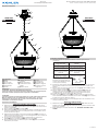
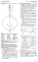
Fixture Diagram
Parts List
Cauons
CAUTION – RISK OF SHOCK –
Disconnect Power at the main circuit breaker panel or main fusebox before
starng and during the installaon.
WARNING:
This xture is intended for installaon in accordance with the Naonal Electrical
Code (NEC) and all local code specicaons. If you are not familiar with code
requirements, installaon by a cered electrician is recommended.
Installaon Instrucons
[A] Glass
[B] Basket
[C] Canopy Screws
[D] Large Loop
[E] Small Loop
[F] Chain
[G] Chain Links
[H] Mounting Strap
[I] Strap Mounting
Screws
[J] Outlet Box
[K] Canopy
[L] Hexnut
[M] Lockwasher
[N] Support Cables
[O] Fixture / Upper
Body
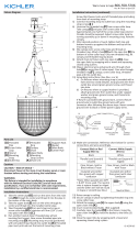
CHAIN HUNG MOUNT:
1) Aach mounng strap[H] to outlet box[J] using the supplied strap mounng
screws[I]. The mounng strap can be adjusted to suit posion of xture.
2) Aach large loop[D] to xture[O].
3) Aach chain[F] to large loop by opening one chain link, close the open links
by wrapping with a towel and squeezing closed using pliers.
4) Aach other end of chain to small loop[E] by opening one chain link, close
the open links by wrapping with a towel and squeezing closed using pliers.
5) If not already installed, install the small loop to the ceiling canopy[K] with
the lock washer[M] and the hexnut[L].
6) Weave electrical wire and ground wire through the chain[F] no more than 3
inches apart.
7) Grounding instrucons: (See Illus. a or b).
a) On xtures where mounng strap is provided with a hole and two raised
dimples, wrap ground wire from outlet box around green ground screw,
and thread into hole.
b) On xtures where a cupped washer is provided,aach ground wire from
outlet box under cupped washer and green ground screw, then thread
into mounng strap.
Installaon Instrucons (connued)
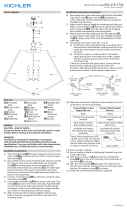
SEMI-FLUSH MOUNT:
1) Aach mounng strap[H] to outlet box[J] using the supplied strap mounng
screws[I]. The mounng strap can be adjusted to suit posion of xture.
2) Follow steps 7 through 14 from “CHAIN HUNG MOUNT” Instrucons.
J
F
K
G
N
O
A
K
H
I
C
L
E
M
B
D
CHAIN HUNG
MOUNT
SEMI-FLUSH
MOUNT

IS-42389-US
Estamos aquí para ayudarle 866-558-5706
Horario: Lunes-Viernes 9am a 5pm EST (hora ocial del este)
Si la lámpara viene con alambre a erra, conecter el alambre a erra de la
lámpara al alambre a erra de la caja tomacorriente con un conector de
alambres espués de seguir los pasos anteriores. Nunca conectar el alambra a
erra a los alambres eléctros negro o blanco.
8) Haga les conexiones de los alambres. La tabla de referencia de abajo indica las
conexiones correctas y los alambres correspondientes.
Conectar el alambre de
suministro negro o rojo al
Conectar el alambre de
suministro blanco al
Negro Blanco
*Cordon paralelo (redondo
y liso)
*Cordon paralelo (cuadrado
y estriado)
Claro, marrón, amarillio
o negro sin hebra
idencadora
Claro, marrón, amarillio
o negro con hebra
idencadora
Alambre aislado (diferente
del verde) con conductor
de cobre
Alambre aislado (diferente
del verde) con conductor
de plata
*Nota: Cuando se uliza alambre
paralelo (SPT 1 y SPT 2). El alambre
neutro es de forma cuadrada o
estriada y el otro alambre será
de forma redonda o lisa. (Vea la
ilustracíón).
Hilo Neutral
9) Suba el escudete al cielorraso. NOTA: Asegúrese de que los cables no queden
atrapados entre el escudete y el techo.
10) Asegure el escudete en su lugar ajustando los dos (2) tornillos del
escudete[C] en los costados del escudete del cielorraso[K].
11) Fije los cables de soporte[N] al cuerpo superior[O] usando los eslabones
de cadena abiertos[G]. Cierre los eslabones abiertos envolviéndolos con un
paño y usando una pinza apriete hasta cerrarlos.
12) Instale las bombillas recomendadas (No suministradas).
13) Coloque el vidrio[A] en la cesta[B] y cuidadosamente suba la cesta hacia el
artefacto. Use los eslabones de cadena abiertos[G] para enganchar la sesta a
los tres (3) cables de soporte.
14) Cierre los eslabones abiertos envolviéndolos con un paño y usando una pinza
apriete hasta cerrarlos.
ARANDELA
CONCAVA
TIERRA DE LA
CAJA DE SALIDA
TORNILLO DE TIERRA,
VERDE
DEPRESIONES
TIERRA
ARTEFACTO
CONECTOR DE ALAMBRE
TIERRA DE LA
CAJA DE SALIDA
TORNILLO DE TIERRA,
VERDE
TIERRA
ARTEFACTO
a
b
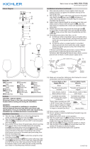
Diagrama de Accesorios
Lista de Partes
[A] Vidrio
[B] Cesta
[C] Tornillos del
Escudete
[D] Anillo Grande
[E] Anillo Pequeño
[F] Cadena
[G] Eslabones de
Cadena Abiertos
[H] Correa de Montaje
[I] Tornillos de Montaje
de la Correa
[J] Caja de Salida
[K] Escudete
[L] Tuerca Hexagonal
[M] Arandela de
Seguridad
[N] Cables de Soporte
[O] Artefacto / Cuerpo
Superior
Precauciones
PRECAUCIÓN – RIESGO DE DESCARGA ELÉCTRICA –
Desconecte la electricidad en el panel principal del interruptor automáco o
caja principal de fusibles antes de comenzar y durante la instalación.
ADVERTENCIA:
Este accesorio está desnado a la instalación de acuerdo con el Naonal
Electrical Code (NEC) y todas las especicaciones del código local. Si no está
familiarizado con los requisitos del código, la instalación se recomienda un
electricista cercado.
Instrucciones de Instalación
MONTAJE CON CADENA COLGANTE:
1) Fije la correa de montaje[H] a la caja de salida[J] con los tornillos de montaje
de la correa[I]. La correa de montaje se puede ajustar para adaptarse a la
posición del aparato.
2) Fije el anillo grande[D] al artefacto[O].
3) Fije la cadena[F] al anillo grande abriendo un eslabón de cadena, cierre los
eslabones abiertos envolviéndolos con un paño y usando una pinza apriete
hasta cerrarlos.
4) Fije el otro extremo de la cadena al anillo pequeño[E] abriendo un eslabón
de cadena, cierre los eslabones abiertos envolviéndolos con un paño y
usando una pinza apriete hasta cerrarlos.
5) Si aún no está instalado, instale el anillo pequeño al escudete del
cielorraso[K] con la arandela de seguridad[M] y la tuerca hexagonal[L].
6) Entrelace el cable eléctrico y el conductor de erra a través de cadena[F] con
una separación no mayor de 3 pulgadas.
7) Instrucciones de conexión a erra solamente para los Estados Unidos. (Vea la
ilustracion a o b).
a) En las lámparas que enen el eje, de montaje con un agujero y dos
hoyuelos realzados, enrollar el alambre a erra de la caja tomacorriente
alrededor del tornillo verde y pasarlo por el aquiero.
b) En las lámparas con una arandela acopada, jar el alambre a erra de la
caja tomacorriente del ajo de la arandela acoada y tornillo verde, y paser
por el eje de montaje.
Instrucciones de Instalación (connuación)
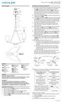
MONTAJE SEMI AL RAS:
1) Fije la correa de montaje[H] a la caja de salida[J] con los tornillos de montaje
de la correa[I]. La correa de montaje se puede ajustar para adaptarse a la
posición del aparato.
2) Siga los pasos 7-14 de las Instrucciones para ‘’MONTAJE CON CADENA
COLGANTE”.
J
F
K
G
N
O
A
K
H
I
C
L
E
M
B
D
J
F
K
G
N
O
A
K
H
I
C
L
E
M
B
D
MONTAJE
CON CADENA
COLGANTE
MONTAJE SEMI
AL RAS

We’re here to help 866-558-5706
Hrs: M-F 9am to 5pm EST
If xture is provided with ground wire, connect xture ground wire to outlet
box ground wire with wire connector aer following the above steps. Never
connect ground wire to black or white power supply wires.
8) Make wire connecon. Reference chart below for correct connecons and
wire accordingly.
Connect Black or Red
Supply Wire to:
Connect White Supply
Wire to:
Black White
*Parallel cord (round &
smooth)
*Parallel cord (square &
ridged)
Clear, Brown, Gold or
Black without Tracer
Clear, Brown, Gold or Black
with Tracer
Insulated wire (other
than green) with copper
conductor
Insulated wire (other
than green) with silver
conductor
*Note: When parallel wire (SPT
1 & SPT 2) are used. The neutral
wire is square shaped or ridged
and the other wire will be round
in shape or smooth
(see illus.)
Neutral Wire
9) Raise canopy to the ceiling. NOTE: Be certain wires do not get pinched
between canopy and ceiling.
10) Secure canopy in place by ghtening the two (2) canopy screws[C] by
installing into the sides of the ceiling canopy[K].
11) Aach the support cables[N] to the upper body[O] using the open chain
links[G]. Close the open links by wrapping with a towel and squeezing closed
using pliers.
12) Insert recommended bulbs (Not supplied).
13) Place glass[A] into the basket[B] and carefully raise the basket to the xture.
Use the open chain links[G] to hook the basket to the three (3) support
cables.
14) Close the open links by wrapping with a towel and squeezing closed using
pliers.
GREEN GROUND
SCREW
CUPPED
WASHER
OUTLET BOX
GROUND
FIXTURE
GROUND
DIMPLES
WIRE CONNECTOR
OUTLET BOX
GROUND
GREEN GROUND
SCREW
FIXTURE
GROUND
a
b
J
F
K
G
N
O
A
K
H
I
C
L
E
M
B
D
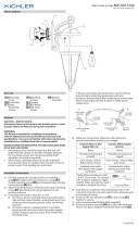
Fixture Diagram
Parts List
Cauons
CAUTION – RISK OF SHOCK –
Disconnect Power at the main circuit breaker panel or main fusebox before
starng and during the installaon.
WARNING:
This xture is intended for installaon in accordance with the Naonal Electrical
Code (NEC) and all local code specicaons. If you are not familiar with code
requirements, installaon by a cered electrician is recommended.
Installaon Instrucons
[A] Glass
[B] Basket
[C] Canopy Screws
[D] Large Loop
[E] Small Loop
[F] Chain
[G] Chain Links
[H] Mounting Strap
[I] Strap Mounting
Screws
[J] Outlet Box
[K] Canopy
[L] Hexnut
[M] Lockwasher
[N] Support Cables
[O] Fixture / Upper
Body
CHAIN HUNG MOUNT:
1) Aach mounng strap[H] to outlet box[J] using the supplied strap mounng
screws[I]. The mounng strap can be adjusted to suit posion of xture.
2) Aach large loop[D] to xture[O].
3) Aach chain[F] to large loop by opening one chain link, close the open links
by wrapping with a towel and squeezing closed using pliers.
4) Aach other end of chain to small loop[E] by opening one chain link, close
the open links by wrapping with a towel and squeezing closed using pliers.
5) If not already installed, install the small loop to the ceiling canopy[K] with
the lock washer[M] and the hexnut[L].
6) Weave electrical wire and ground wire through the chain[F] no more than 3
inches apart.
7) Grounding instrucons: (See Illus. a or b).
a) On xtures where mounng strap is provided with a hole and two raised
dimples, wrap ground wire from outlet box around green ground screw,
and thread into hole.
b) On xtures where a cupped washer is provided,aach ground wire from
outlet box under cupped washer and green ground screw, then thread
into mounng strap.
Installaon Instrucons (connued)
SEMI-FLUSH MOUNT:
1) Aach mounng strap[H] to outlet box[J] using the supplied strap mounng
screws[I]. The mounng strap can be adjusted to suit posion of xture.
2) Follow steps 7 through 14 from “CHAIN HUNG MOUNT” Instrucons.
J
F
K
G
N
O
A
K
H
I
C
L
E
M
B
D
CHAIN HUNG
MOUNT
SEMI-FLUSH
MOUNT

IS-42389-CB
Nous sommes là pour vous aider 866-558-5706
Heures : du lundi au vendredi, de 9h à 17h (heure de l’Est)
INSTRUCTIONS:
For Assembling and Installing Fixtures in Canada
Pour L’assemblage et L’installaon Au Canada
MONTAGE SUSPENDU AVEC CHAÎNE :
1) Aachez la sangle de xaon[H] à la boîte de sore[J] à l’aide des vis de
xaon de la sangle[I]. sangle de xaon peut être ajustée en foncon de la
posion de montage.
2) Fixez la grande boucle[D] au luminaire[O].
3) Aachez la chaîne[F] à la grande boucle en ouvrant un maillon de la chaîne,
fermez les maillons ouverts en les enveloppant avec une serviee et en les
serrant à l’aide d’une pince.
4) Aachez l’autre extrémité de la chaîne à la pete boucle[E] en ouvrant un
maillon, fermez les maillons ouverts en les enveloppant avec une serviee et
en les serrant à l’aide d’une pince.
5) S’il n’est pas encore installé, installez la pete boucle sur le cache du
plafond[K] avec la rondelle frein[M] et le contre-écrou[L].
6) Passez le l électrique et le l de terre par la chaîne[F] avec un intervalle
maximal de 7,5 cm entre.
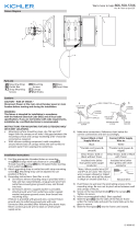
Diagramme d’appareils
ATTENTION – RISQUE DE DÉCHARGES ÉLECTRIQUES -
Couper le courant au niveau du panneau du disjoncteur du circuit principal ou
de la boîte à fusibles principale avant de procéder à l’installaon.
ATTENTION:
Ce luminaire doit être installé conformément aux codes d’électricité naonaux
(NEC) et sasfaire toutes les spécicaons des codes locaux. Si vous ne
connaissez pas les exigences de ces codes, il est recommandé de coner
l’installaon à un électricien ceré.
Liste des Pièces
Précauons
[A] Verre
[B] Panier
[C] Vis du Cache
[D] Grande Boucle
[E] Petite Boucle
[F] Chaîne
[G] Maillons Ouverts de
la Chaîne
[H] Sangle de Fixation
[I] Vis de Fixation de la
Sangle
[J] Boîte de Sortie
[K] Cache
[L] Contre-Écrou
[M] Rondelle Frein
[N] Câbles de Support
[O] Luminaire / Pare
Supérieure
Instrucons d’installaon
J
F
K
G
N
O
A
K
H
I
C
L
E
M
B
D
MONTAGE SEMI-ENCASTRÉ :
1) Aachez la sangle de xaon[H] à la boîte de sore[J] à l’aide des vis de
xaon de la sangle[I]. Sangle de xaon peut être ajustée en foncon de la
posion de montage.
2) Suivez les Étapes 7 à 13 des instrucons de “MONTAGE SUSPENDU AVEC
CHAÎNE”.
J
F
K
G
N
O
A
K
H
I
C
L
E
M
B
D
Instrucons d’installaon (suite)
7) Connecter les ls. Se reporter au tableau ci-dessous pour faire les
connexions.
Connecter le l noir ou
rouge de la boite
Connecter le l blanc de
la boîte
A Noir A Blanc
*Au cordon parallèle (rond
et lisse)
*Au cordon parallèle (à
angles droits el strié)
Au transparent, doré,
marron, ou noir sans l
disncf
Au transparent, doré,
marron, ou noir avec un l
disncf
Fil isolé (sauf l vert) avec
conducteur en cuivre
Fil isolé (sauf l vert) avec
conducteur en argent
*Remarque: Avec emploi d’un
l paralléle (SPT 1 et SPT 2). Le
l neutre est á angles droits ou
strié et l’autre l doit étre rond
ou lisse (Voir le schéma).
Fil Neutre
8) Soulevez le cache jusqu’au plafond. REMARQUE : Vous assurer que tous les
ls sont dans le cache et ne se retrouvent pas pincés entre le cache et le
plafond.
9) Fixez le cache en serrant les deux (2) vis du cache[C] en les installant sur les
côtés du cache du plafond[K].
10) Fixez les câbles de support[N] sur la pare supérieure[O] à l’aide des
maillons ouverts de la chaîne[G]. Fermez les maillons ouverts en les
enveloppant avec une serviee et en les serrant à l’aide d’une pince.
11) Installez les ampoules recommandées (Non fournies).
12) Placez le verre[A] dans le panier[B] et soulevez avec précauon le panier
vers le luminaire. Ulisez les maillons ouverts de la chaîne[G] pour accrocher
le panier aux trois (3) câbles de support.
13) Fermez les maillons ouverts en les enveloppant avec une serviee et en les
serrant à l’aide d’une pince.
MONTAGE
SUSPENDU AVEC
CHAÎNE
MONTAGE
SEMI-ENCASTRÉ
-
 1
1
-
 2
2
-
 3
3
-
 4
4


Kichler Lighting 42389NBR Manuel utilisateur
- Taper
- Manuel utilisateur
dans d''autres langues
Documents connexes
-
 Kichler Lighting 42376BK Manuel utilisateur
-
 Kichler Lighting 49234BSL Manuel utilisateur
-
 Kichler Lighting 49233BSL Manuel utilisateur
-
 Kichler Lighting 49288OZ Manuel utilisateur
-
 Kichler Lighting 49287OZ Manuel utilisateur
-
 Kichler Lighting 42138BK Manuel utilisateur
-
 Kichler Lighting 43034DAG Manuel utilisateur
-
 Kichler Lighting 49286OZ Manuel utilisateur
-
 Kichler Lighting 44377BK Manuel utilisateur
-
 Kichler Lighting 43035DAG Manuel utilisateur


