GrandAire Concentric Vent Termination Kit for Condensing Furnaces Guide d'installation
- Taper
- Guide d'installation

Installation Instructions
Concentric Vent Termination Kit for Condensing Furnaces
INTRODUCTION
These instructions are intended to assist qualifi ed
individuals in the proper installation of this concentric
vent termination kit. If these instructions differ from those
packaged with the furnace, follow these instructions.
READ ALL INSTRUCTIONS CAREFULLY BEFORE
STARTING THE INSTALLATION.
SAFETY CONSIDERATIONS
Installing and servicing heating equipment can be
hazardous due to gas and electrical components. Only
trained personnel should install or service heating
equipment. Untrained personnel can perform basic
maintenance such as cleaning coils, or cleaning and
replacing fi lters. All other operations should be performed
by trained service personnel. When working on heating
equipment, observe all precautions in the literature, and
on tags and labels attached to the unit. Follow all safety
codes. Wear glasses and work gloves, and have a fi re
extinguisher available.
WARNING!
Electric shock hazard. Disconnect all electrical
power to the appliance before beginning any
installation or modifi cation.
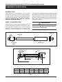
Figure 1. Kit Components
Inside Pipe
Y Concentric
Fittin
g
Outside Pipe
Rain Cap
Figure 2. Dimensions
B
1 3/16
1 1/2
D
F
A
E
C In. Dia.
Table 1.
Kit No. A B C D E F
904953 (3”) 38 7/8 3 4 1/2 21 1/8 7 3/8 6 1/2
904952 (2”) 33 /38 2 3 1/2 16 5/8 6 1/4 5 3/4

2
SPECIAL VENTING REQUIREMENTS FOR
INSTALLATIONS IN CANADA
Installation in Canada must conform to the requirements
of CSA B149 code. Vent systems must be composed of
pipe, fi ttings, cements, and primers listed to ULC S636.
This concentric vent termination kit has been certifi ed
to ULC S636 for use with those IPEX PVC vent com-
ponents which have been certifi ed to this standard. In
Canada, the primer and cement must be of the same
manufacturer as the vent system; do not mix primers
and cements from one manufacturer with a vent system
from a different manufacturer. Follow the manufacturer’s
instructions in the use of primer and cement and never
use primer or cement beyond its expiration date.
The safe operation, as defi ned by ULC S636, of the vent
system and this termination kit is based on following
these installation instructions, the vent system manufac-
turer’s installation instructions, and proper use of primer
and cement. Acceptability under Canadian standard CSA
B149 is dependent upon full compliance with all installa-
tion instructions. Under this standard, it is recommended
that the vent system be checked once a year by qualifi ed
service personnel. The authority having jurisdiction (gas
inspection authority, municipal building department, fi re
department, etc) should be consulted before installation
to determine the need to obtain a permit.
CONSIGNES SPÉCIALES POUR
L’INSTALLATION DE VENTILLATION AU
CANADA
L’installation faite au Canada doit se conformer aux
exigences du code CSA B149. Ce systême de ventilla-
tion doit se composer de tuyaux, raccords, ciments et
apprêts conformes au ULC S636. Ce systême de ventil-
lation concentrique a été certifi é ULC S636 pour être
utilisé avec les composantes IPEX PVC qui sont cer-
tifi és. Au Canada l’apprêt et le ciment doivent être du
même manufacturier que le systême de ventillation; ne
pas mélanger l’apprêt et le ciment d’un manufacturier
avec le systême de ventillation d’un autre manufactu-
rier. Bien suivre les indications du manufacturier lors
de l’utilisation de l’apprêt et du ciment et ne pas utiliser
ceux--ci si la date d’expiration est atteinte.
Le bon fonctionnement de ce systême de ventillation
est conditionnel à l’installation tel que défi ni par le ULC
S636 c’est à dire: bien suivre les consignes ci--haut
mentionnées ainsi que les instructions du manufactu-
rier et aussi une bonne utilisation de l’apprêt et du ci-
ment. L’acceptation du standard Canadien CSA B419
est directement relié à l’installation conforme aux in-
structions ci--haut mentionnées. Le standard Canadien
recommande l’ inspection par un personel qualifi é et
ce, une fois par année. Les autoritées ayant juridiction
(inspecteurs de gas, inspecteurs en bâtiments, départe-
ment des incendies, etc) devraient être consultées avant
l’installation afi n de déterminer si un permis est requis.
Copyright 2008

3
INSTALLATION
WARNING!
These kits are to be used only for terminating
condensing Category IV furnaces. DO NOT
use kits to terminate Category I, II, or III vent
furnaces. Failure to follow these instructions
could result in fi re, personal injury, or death.
Field supplied pipe and fi ttings are required to complete
the installation. The combustion air and vent pipe fi ttings
must conform to American National Standards Institute
(ANSI) and American Society for Testing and Materials
(ASTM) standards D1785 (schedule-40 PVC), or D2665
(PVC-DWV), or D2441 (SDR-21 and SDR-26 PVC), or
D2661 (ABS-DWV), or F628 (schedule-40 ABS). Pipe
cement and primer must conform to ASTM standards
D2564 (PVC) or D2235 (ABS).
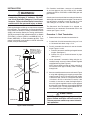
Figure 3. Roof Installation
Maintain 12" (18" for
Canada) Min. clearance
above roof or highest
anticipated snow level,
max. 24" above roof.
Combustion
Air
Support
(Field Supplied)
Vent
Combustion Air
45˚ Elbow
(Field Supplied)
Roof Boot/
Flashing
(Field Supplied)
Vent
For Canadian installations, construct all combustion
air and vent pipes for this unit of CSA or ULC certifi ed
schedule-40 PVC or PVC-DWV, or ABS-DWV pipe and
pipe cement.
Consult your furnace installation instructions for the allow-
able length and size of the plastic vent pipe. The concentric
vent termination assembly is equal to 4 feet of 3" inlet
and outlet pipe, or 3 feet of 2" inlet and outlet pipe.
The Concentric Vent Termination Kit is shipped as-
sembled but not cemented. Disassemble the kit and
cement per Figures 1 and 2.
Procedure 1 - Roof Termination
1. Determine the best location for termination kit.
2. Cut one hole, 5 inch diameter when using a 3" kit or
a 4" diameter hole when using a 2" kit.
3. Partially assemble the concentric vent termination
kit per Figures 1 and 2.
a. Cement Y concentric vent fi tting to larger diameter
kit pipe. (See fi gure 1.)
b. Cement rain cap to smaller diameter kit pipe.
(See fi gure 1.)
4. Install cemented Y concentric fi tting and pipe as-
sembly through structure's hole and fi eld supplied
roof boot/fl ashing (See Figure 3).
NOTE: do not allow insulation or other materials to
accumulate inside pipe assembly when installing
through hole.
5. Secure assembly to roof structure as shown in Figure
3 using fi eld supplied metal strapping or equivalent
support material. NOTE: Ensure termination height
is above the roof surface or anticipated snow level
(12 inches in U.S.A. or 18 inches in Canada). If the
assembly is too short to meet the height require-
ment, the 2 pipes supplied in the kit may be replaced
by using the same diameter, fi eld supplied SDR-26
PVC (D2241) pipe. Do not expand dimension "D"
more than 60 inches (See Figure 2).
CAUTION:
DO NOT use fi eld supplied couplings to extend
pipes. Airfl ow restriction will occur and the
furnace pressure switch may cause intermit-
tent operation.

4
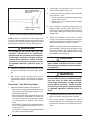
NOTE: Instead of cementing the smaller pipe to the
rain cap, a fi eld-supplied stainless steel screw may be
used to secure the 2 components together when fi eld
disassembly is desired for cleaning. (See Figure 4.)
WARNING!
Do not operate the furnace with rain cap
removed. Recirculation of combustion
products may occur, or water may accumulate
inside larger combustion air pipe and fl ow
into the burner enclosure. Failure to follow
this warning could result in product damage
or improper operation, personal injury or
death.
6. Cement fi eld supplied furnace combustion air and
vent pipes to concentric vent termination assem-
bly.
7. Run furnace through a complete heat cycle to
ensure combustion air and vent pipes are properly
connected to concentric vent termination connec-
tions.
Procedure 2 - Side Wall Termination
1. Determine the best location for termination kit.
• Termination kit should be positioned where the
vent vapors will not damage plants/shrubs, or air
conditioning equipment.
• Termination kit should be positioned where it will
not be affected by wind eddies or currents that
may allow recirculation of combustion products
or unwanted intake of airborne leaves or light
snow.
• Termination kit should not be positioned where
it may be damaged by foreign objects such as
stones, balls, etc.
• Termination kit should not be positioned where
the vapors may be objectionable.
2. Cut one hole, 5 inch diameter if using a 3" kit or a
4 inch diameter hole if using 2" kit.
3. Partially assemble the concentric vent termination
kit per Figures 1 and 2.
a. Cement Y concentric vent fi tting to larger diameter
kit pipe. (See Figure 1.)
b. Cement rain cap to smaller diameter kit pipe.
(See Figure 1.)
4. Install cemented Y concentric fi tting and pipe as-
sembly through structure's hole (See Figure 5).
NOTE: do not allow insulation or other materials to
accumulate inside pipe assembly when installing
through hole.
5. Secure the assembly to the structure as shown
in Figure 5 using fi eld supplied metal strapping or
equivalent support material. NOTE: Ensure termina-
tion location clearance as shown in Figure 5.
NOTE: If assembly needs to be extended, the 2
pipes supplied in the kit may be replaced by using
the same diameter, fi eld supplied SDR-26 PVC
(D2241) pipe. Do not expand dimension "D" more
than 60 inches (See Figure 2).
CAUTION:
DO NOT use fi eld supplied couplings to extend
pipes. Airfl ow restriction will occur and the
furnace pressure switch may cause intermit-
tent operation.
WARNING!
Do not operate the furnace with rain cap
removed. Recirculation of combustion prod-
ucts may occur, or water may accumulate
inside larger combustion air pipe and fl ow
into the burner enclosure. Failure to follow
this warning could result in product damage
or improper operation, personal injury or
death.
6. Cement fi eld supplied furnace combustion air and vent
pipes to concentric vent termination assembly.
7. Run furnace through a complete heat cycle to
ensure combustion air and vent pipes are properly
connected to concentric vent termination connec-
tions.
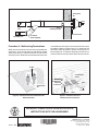
Figure 4. Rain Cap to Vent Pipe Alternate Assembly
DRILL CLEARANCE HOLE IN
RAIN CAP AND PILOT HOLE
IN VENT PIPE
STAINLESS STEEL SCREW
(FIELD SUPPLIED)

Combustion
Air
Combustion Air
45° Elbow
(Field Supplied)
Vent
Strap
(Field Supplied)
1" Max. Clearance
Exhaust
Vent
Figure 5. Side Wall Installation
Vent
Vent
8" Min.
Combustion
Air
1" Maximum
(TYP)
12" Minimum
to Maximum
expected
snow level
Vent
8" Min.
Vent
Combustion
Air
Figure 6. Concentric Vent and Combustion-Air
Roof Termination
Figure 7. Concentric Vent and
Combustion-Air Termination
Procedure 3 - Multiventing Terminations
When two or more direct vent furnaces are vented near
each other, each furnace must be individually vented.
(See Figure 6 and 7.) NEVER common vent or breach
vent this furnace. When two or more direct vent furnaces
are vented near each other, each vent termination may by
installed as shown in Figure 6 and 7. It is important that
vent terminations be made as shown to avoid recircula-
tion of fl ue gases. A minimum distance of 18 inches or a
maximum distance of 36 inches MUST be maintained.
¢708999{¤
708999A
O'Fallon, MO
INSTALLER: PLEASE LEAVE THESE INSTALLATION
INSTRUCTIONS WITH THE HOMEOWNER.
708999A (Replaces 7089990)
Specifi cations and illustrations subject
to change without notice and
without incurring obligations
Printed in U.S.A. (03/09)
-
 1
1
-
 2
2
-
 3
3
-
 4
4
-
 5
5


