
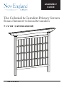
e Colonial & Camden Privacy Screen
7 1/2’X8’ 229CMx266CM
ASSEMBLY
GUIDE
VER 1.4 07/09/19
Écran d’intimité Colonial & Camden

2 VER 1.4 01/09/19
WWW.NEWENGLANDARBORS.COM
WWW.NEWENGLANDARBORS.CO.UK
MATERIALS OVERVIEW
DESCRIPTION DU MATERIEL
3
MATERIALS BREAKDOWN
VENTILATION DES MATERIEL
4
ADDITIONAL MATERIALS
SUPPLÉMENTAIRE MATERIEL
5
STEP 1
ÉTAPE 1
6
STEP 2
ÉTAPE 2
STEP3
ÉTAPE 3
STEP 4
ÉTAPE 4
STEP 5
ÉTAPE 5
7
8/9
10
11
IN THIS GUIDE

VER 1.4 01/09/19 3
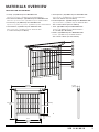
MATERIALS OVERVIEW
1. Post Cap - (x2) 14103 Composite/ 10824 White PVC
Capuchons de poteaux - (x2) 14103 Composite/10824 PVC Blanc
2. Decorative Beam End Caps - (x4) 14003 Composite/ 30015 White PVC
Embouts de poutres décoratifs - (x4) 14003 Composite/ 30015 PVC Blanc
3. Post Trim Caps - (x2) 14104 Composite/ 10737 White PVC
Capuchons de garniture de poteaux - (x2) 14104 Composite/ 10737 PVC Blanc
4. Horizontal Rails - (x2) 14105 Composite/ 10228 White PVC
Barres horizontales - (x2) 14105 Composite/ 10228 PVC Blanc
2” x 3 1/2” x 79 3/4” (5 x 9 x 203cm)
5. Vertical Spindles - (x11) 14106 Composite/ 10229 White PVC
Tiges verticales - (x11) 14106 Composite/ 10229 PVC Blanc
7/8” x 1 1/2” x 65 3/4” x (2 x 3.8 x 167cm)
6. Horizontal Spindles - (x3) 14107 Composite/ 10231 White PVC
Tiges horizontales - (x3) 14107 Composite/ 10231 PVC Blanc
1 1/2” x 1 1/2” x 79 3/4” (3.8 x 3.8 x 203cm)
7. Posts - (x2) 14108 Composite/ 10232 White PVC
Poteaux - (x2) 14108 Composite/ 10232 PVC Blanc
4” x 4” x 90” (10 x 10 x 229cm)
8. Beams - (x2) 14109 Composite/ 10232 White PVC
Poutres - (x2) 14109 Composite/10232 PVC Blanc
1 1/2” x 5 1/2” x 88 1/8“ (3.8 x 14 x 224 cm)
12 in (30.5 cm)
66 in (168 cm)
6 1/2 in
(16.5 cm)
78 in (198 cm)
90 in (229 cm)
Post
72 in
(183 cm)
80 in
(203 cm)
104 5/8 in
(266 cm)
7 1/4 in
(18 cm)
1
2
3
4
5
6
7
8
DESCRIPTION DU MATERIEL

4 VER 1.4 01/09/19
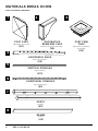
MATERIALS BREAK DOWN
POST TRIM
CAPS
Capuchons de garniture
de poteaux
X2
DECORATIVE
BEAM END CAPS
Embouts de poutres décoratifs
X4
POST CAPS
Capuchons de poteaux
X2
HORIZONTAL RAILS
Barres horizontales
X2
VERTICAL SPINDLES
Tiges verticales
X11
HORIZONTAL SPINDLES
Tiges horizontales
X3
POSTS
Poteaux
X2
BEAMS
Poutres
X2
1
2
8
3
4
5
6
7
VENTILATION DES MATERIEL

VER 1.4 01/09/19 5
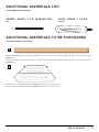
ADDITIONAL MATERIALS LIST
ADDITIONAL MATERIALS TO BE PURCHASED
4x4x6 Ft (10x10x182cm) Pressure Treated Wood for Posts. Cut in two 36” (91cm) lengths. Purchase at local building centre.
QUANTITY: x1
Bois traité sous pression pour les poteaux. Coupez en deux 36 “(91cm) longueurs. Achat au centre de construction local.
QUANTITÉ: x1
Purchase at your local building centre. QUANTITY: x2 (one per post bottom)
Achat au centre de construction local. QUANTITÉ: x2 (un par poteau en bas)
1
2
SCREW 20032 2 1/2” 6.35CM X28 GLUE 20029 1 1/2 OZ
AUTRES MATERIEL À ACHETER
SUPPLÉMENTAIRE MATERIEL
VIS COLLE

6 VER 1.4 01/09/19
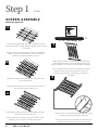
Step 1 ÉTAPE 1
SCREEN ASSEMBLE
2 1/2” 6.35CM X8
Insert the two horizontal rails onto the vertical spindles as shown.
Excessive force should not be used.
Insérez deux barres horizontales sur les tiges verticales comme
illustré.Une force excessive ne devrait pas être utilisée.
Fasten the posts onto the horizontal rails using a total of eight
screws through the pre-drilled holes on the post.
Fixez les poteau aux barres horizontales en utilisant un total
de huit vis à travers les trous pré-creusés sur le poteau.
1A
1B
2
4
3
With a helper stand the screen up on one post rail. Guide the
horizontal spindles into the routed holes. Note the tabs on the
horizontal spindles; once inserted, the spindles will lock into place.
Avec un assistant, placez l’écran sur un rail. Guidez les fuseaux
horizontaux dans les trous déviés. Notez les onglets sur
les broches horizontales; Une fois insérées, les broches se
verrouillent.
ECRAN DE MONTAGE
Layout the horizontal spindles with all the routed holes in line as
shown in 1A) with three vertical spindles positioned at either end and
in the middle.
Disposez les broches horizontales avec tous les trous acheminés
alignés comme indiqué en 1A) avec trois broches verticales
positionnées à chaque extrémité et au centre.
Add the other eight vertical spindles though each of the routed
holes as shown in 1b).
Ajoutez les huit autres broches verticales à travers chacun des
trous acheminés, comme indiqué en 1b).

VER 1.4 01/09/19 7
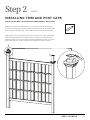
Step 2 ÉTAPE 2
Slide the two post trim caps down the post as shown, followed by the two
post caps. The trim caps can sit on the horizontal rail for now and apply a thin
bead of glue around the edge, underneath the post cap and fit it into place.
Faites glisser les deux capuchons de poteau vers le bas, tel qu’il est montré,
suivis des deux capuchons de poteau. Pour le moment, les capuchons de
garniture peuvent rester sur le rail horizontal et appliquer une fine couche de
colle autour du bord, sous le capuchon de poteau et le mettre en place.
INSTALLING TRIM AND POST CAPS
INSTALLATION DES CAPUCHONS DE GARNITURE ET DE POTEAU

8 VER 1.4 01/09/19
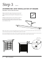
Apply a small amount of glue to the inside of the end cap as
shown and insert onto the beam. Allow 30 seconds for the
glue to set and a few more minutes to cure. Repeat for second
beam.
Appliquez un petit montant de colle à l’intérieur de l’embout
décoratif comme illustré et insérez sur le bout de poutre.
Permettez une période de 30 secondes pour que la colle se
fixe et quelques minutes de plus pour qu’elle sèche. Répétez
pour la deuxième poutre.
With a helper, align one of the beams against the posts as shown. The top of the beam should be at the same level as the
bottom of the post caps and the overhang should be equal on both ends.
Avec un aide, alignez une des poutres contre les poteaux comme illustré. Le haut de la poutre devrait être au même niveau
que le bas des capuchons de poteaux et le surplomb de chaque bout de la poutre devrait être égal.
Step 3 ÉTAPE 3
ASSEMBLING AND INSTALLATION OF BEAMS
13 5/8”
(34.60 cm)
MONTAGE ET INSTALLATION DE POUTRES
Equal Overhang
Égalité sur le blocage

VER 1.4 01/09/19 9
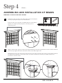
Step 4 ÉTAPE 3
ASSEMBLING AND INSTALLATION OF BEAMS
Fasten the beam onto the posts using eight screws as shown (four
at each post). Repeat steps for the second beam.
Fixez la poutre sur les poteaux en utilisant huit vis comme illustré
(quatre pour chaque poteau). Répétez cette étape pour la
deuxième poutre.
Apply a small amount of glue around the post approximately 1 inch (2.5 cm) below the beams as shown. Slide the
post trim caps against the beam and hold for 30 seconds until the glue sets.
Appliquez un peu de colle autour du poteau environ 1 pouce (2,5 cm) du bas des poutres comme illustré. Glissez
les capuchons de garniture de poteaux contre les poutres et tennez-les en place pour 30 secondes pour
permettre la colle de se fixer.
1
2
2 1/2” 6.35CM X16
MONTAGE ET INSTALLATION DE POUTRES

10 VER 1.4 01/09/19
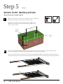
Step 5 ÉTAPE 4
Within your desired area, dig two, 8” (20 cm) diameter x 24“ (60 cm)
deep holes, 76” apart from each other center to center.
Dans la zone souhaitée, creusez deux trous de 8 ”(20 cm) de
diamètre sur 24” de profondeur sur 76 ”(193 cm), à 76” l’un de
l’autre, centre à centre.
Insert the two 4x4x36” (10 x10 x 91 cm) pressure treated wood posts into the bottom of the vinyl post until it
bottoms out against the horizontal rail. Fasten with two screws each (not included).
Insérez les deux poteaux de bois traité sous pression de 4x4x36” (10 x10 x 91 cm) dans les pieds des poteux en
vinyle jusqu’au point où ils contactent la barre horizontale. Fixez avec deux vis dans chaque poteau (pas incluses).
WOOD POST INSTALLATION
1
2
24 in (60cm)
76in
(193cm)
8 in Dia
(20cm)
Ground
Sol
INSTALLATION DE POTEAU EN BOIS

VER 1.4 01/09/19 11
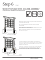
Step 6 ÉTAPE 5
WOOD POST AND VINYL COLUMN ASSEMBLY
With a helper, place the privacy screen posts into the holes and level it
both vertically and horizontally.
Note: for asthestics purposes, the screws on the posts should
be facing away.
Avec un aide, placez les poteaux de l’écran d’intimité dans les trous et
nivelez verticalement et horizontalement.
Notez: pour maintenir l’esthétique, les vis sur les poteaux devraient
faire face au sesn opposé.
To prevent the privacy screen from “sinking”, place a few bricks or
wood pieces below the bottom horizontal rail. The bottom horizontal rail
should be 12” (30.5 cm) o the ground. Backfill the holes with cement
and allow it to set and cure.
Pour prévenir “l’enfoncement” de l’écran dans le sol, placez quelques
blocs de bois dessous la barre horizontale inférieure. Cette barre
devrait être élevée du 12” (30,5 cm) du niveau du sol. Remblayez les
trous avec du béton et permettez le béton de se fixer et saisir.
12” (30.5cm)
POTEAU EN BOIS ET ENSEMBLE DE COLONNE DE VINYLE
Bricks
Briques
-
 1
1
-
 2
2
-
 3
3
-
 4
4
-
 5
5
-
 6
6
-
 7
7
-
 8
8
-
 9
9
-
 10
10
-
 11
11


New England Arbors Camden Privacy Screen Manuel utilisateur
- Taper
- Manuel utilisateur
- Ce manuel convient également à
dans d''autres langues
Autres documents
-
Vita Camden Privacy Screen Mode d'emploi
-
Vita Split Rail Corner Fence Mode d'emploi
-
-
-
-
-
-
RDI 73019125 Mode d'emploi
-
Arrow IWC108 Manuel utilisateur
-
 Arrow Storage Products IWC1012 Manuel utilisateur
