Miller Auto-Axcess 450 Le manuel du propriétaire
- Catégorie
- Système de soudage
- Taper
- Le manuel du propriétaire
Ce manuel convient également à

OM-210 540B
May 2003
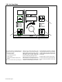
Auto Axcess 450
Processes
Description
MIG (GMAW) Welding
Pulsed MIG (GMAW-P)
Flux Cored (FCAW) Welding
Automatic Welding
Automatic Welding Interface And
Arc Welding Power Source
Visit our website at
www.MillerWelds.com

Miller Electric manufactures a full line
of welders and welding related equipment.
For information on other quality Miller
products, contact your local Miller distributor to receive the latest full
line catalog orindividual catalog sheets. To locate your nearest
distributor or service agency call 1-800-4-A-Miller, or visit us at
www.MillerWelds.com on the web.
Thank you and congratulations on choosing Miller. Now you can get
the job done and get it done right. We know you don’t have time to do
it any other way.
That’s why when Niels Miller first started building arc welders in 1929,
he made sure his products offered long-lasting value and superior
quality. Like you, his customers couldn’t afford anything less. Miller
products had to be more than the best they could be. They had to be the
best you could buy.
Today, the people that build and sell Miller products continue the
tradition. They’re just as committed to providing equipment and service
that meets the high standards of quality and value established in 1929.
This Owner’s Manual is designed to help you get the most out of your
Miller products. Please take time to read the Safety precautions. They
will help you protect yourself against potential hazards on the worksite.
We’ve made installation and operation quick
and easy. With Miller you can count on years
of reliable service with proper maintenance.
And if for some reason the unit needs repair,
there’s a Troubleshooting section that will
help you figure out what the problem is. The
parts list will then help you to decide the
exact part you may need to fix the problem.
Warranty and service information for your
particular model are also provided.
Miller is the first welding
equipment manufacturer in
the U.S.A. to be registered to
the ISO 9001:2000 Quality
System Standard.
Working as hard as you do
– every power source from
Miller is backed by the most
hassle-free warranty in the
business.
From Miller to You
Miller offers a Technical
Manual which provides
more detailed service and
parts information for your
unit. To obtain a Technical
Manual, contact your local
distributor. Your distributor
can also supply you with
Welding Process Manuals
such as SMAW, GTAW,
GMAW, and GMAW-P.

The following terms are
used interchangeably
throughout this manual:
MIG = GMAW
TABLE OF CONTENTS
SECTION 1 – SAFETY PRECAUTIONS - READ BEFORE USING 1. . . . . . . . . . . . . . . . . . . . . . . . . . . .
1-1. Symbol Usage 1. . . . . . . . . . . . . . . . . . . . . . . . . . . . . . . . . . . . . . . . . . . . . . . . . . . . . . . . . . . . . . . .
1-2. Arc Welding Hazards 1. . . . . . . . . . . . . . . . . . . . . . . . . . . . . . . . . . . . . . . . . . . . . . . . . . . . . . . . . .
1-3. Additional Symbols For Installation, Operation, And Maintenance 3. . . . . . . . . . . . . . . . . . . . .
1-4. Principal Safety Standards 3. . . . . . . . . . . . . . . . . . . . . . . . . . . . . . . . . . . . . . . . . . . . . . . . . . . . .
1-5. EMF Information 4. . . . . . . . . . . . . . . . . . . . . . . . . . . . . . . . . . . . . . . . . . . . . . . . . . . . . . . . . . . . . .
SECTION 1 – CONSIGNES DE SECURITE – LIRE AVANT UTILISATION 5. . . . . . . . . . . . . . . . . . . . .
1-1. Signification des symboles 5. . . . . . . . . . . . . . . . . . . . . . . . . . . . . . . . . . . . . . . . . . . . . . . . . . . . .
1-2. Dangers relatifs au soudage à l’arc 5. . . . . . . . . . . . . . . . . . . . . . . . . . . . . . . . . . . . . . . . . . . . . .
1-3. Dangers supplémentaires en relation avec l’installation, le fonctionnement
et la maintenance 7. . . . . . . . . . . . . . . . . . . . . . . . . . . . . . . . . . . . . . . . . . . . . . . . . . . . . . . . . . . . .
1-4. Principales normes de sécurité 8. . . . . . . . . . . . . . . . . . . . . . . . . . . . . . . . . . . . . . . . . . . . . . . . . .
1-5. Information sur les champs électromagnétiques 8. . . . . . . . . . . . . . . . . . . . . . . . . . . . . . . . . . . .
SECTION 2 – INSTALLATION 9. . . . . . . . . . . . . . . . . . . . . . . . . . . . . . . . . . . . . . . . . . . . . . . . . . . . . . . . . . .
2-1. Specifications 9. . . . . . . . . . . . . . . . . . . . . . . . . . . . . . . . . . . . . . . . . . . . . . . . . . . . . . . . . . . . . . . .
2-2. Dimensions And Weight 9. . . . . . . . . . . . . . . . . . . . . . . . . . . . . . . . . . . . . . . . . . . . . . . . . . . . . . . .
2-3. Duty Cycle And Overheating 10. . . . . . . . . . . . . . . . . . . . . . . . . . . . . . . . . . . . . . . . . . . . . . . . . . . .
2-4. Volt-Ampere Curves 10. . . . . . . . . . . . . . . . . . . . . . . . . . . . . . . . . . . . . . . . . . . . . . . . . . . . . . . . . . .
2-5. Selecting A Location 11. . . . . . . . . . . . . . . . . . . . . . . . . . . . . . . . . . . . . . . . . . . . . . . . . . . . . . . . . . .
2-6. Connection Diagram 11. . . . . . . . . . . . . . . . . . . . . . . . . . . . . . . . . . . . . . . . . . . . . . . . . . . . . . . . . . .
2-7. Rear Panel Receptacles And Circuit Breakers 12. . . . . . . . . . . . . . . . . . . . . . . . . . . . . . . . . . . . .
2-8. Connecting To Weld Terminals 12. . . . . . . . . . . . . . . . . . . . . . . . . . . . . . . . . . . . . . . . . . . . . . . . . .
2-9. Selecting Weld Cable Sizes* 13. . . . . . . . . . . . . . . . . . . . . . . . . . . . . . . . . . . . . . . . . . . . . . . . . . . .
2-10. Peripheral Receptacle Functions 14. . . . . . . . . . . . . . . . . . . . . . . . . . . . . . . . . . . . . . . . . . . . . . . .
2-11. Electrical Service Guide 14. . . . . . . . . . . . . . . . . . . . . . . . . . . . . . . . . . . . . . . . . . . . . . . . . . . . . . . .
2-12. Connecting Input Power 15. . . . . . . . . . . . . . . . . . . . . . . . . . . . . . . . . . . . . . . . . . . . . . . . . . . . . . . .
2-13. Touch Sensor Operation 15. . . . . . . . . . . . . . . . . . . . . . . . . . . . . . . . . . . . . . . . . . . . . . . . . . . . . . .
SECTION 3 – OPERATION 16. . . . . . . . . . . . . . . . . . . . . . . . . . . . . . . . . . . . . . . . . . . . . . . . . . . . . . . . . . . . .
3-1. Operational Terms 16. . . . . . . . . . . . . . . . . . . . . . . . . . . . . . . . . . . . . . . . . . . . . . . . . . . . . . . . . . . .
3-2. Front Panel Controls (See Section 3-3) 17. . . . . . . . . . . . . . . . . . . . . . . . . . . . . . . . . . . . . . . . . . .
3-3. Front Panel Controls - Continued (See Section 3-2) 18. . . . . . . . . . . . . . . . . . . . . . . . . . . . . . . . .
Table 3-1. Welding Wire Abbreviations* 18. . . . . . . . . . . . . . . . . . . . . . . . . . . . . . . . . . . . . . . . . . . . . . . .
Table 3-2. Welding Gas Abbreviations* 18. . . . . . . . . . . . . . . . . . . . . . . . . . . . . . . . . . . . . . . . . . . . . . . . .
Table 3-3. Robot Abbreviations* 18. . . . . . . . . . . . . . . . . . . . . . . . . . . . . . . . . . . . . . . . . . . . . . . . . . . . . .
3-4. Front Panel Switches 19. . . . . . . . . . . . . . . . . . . . . . . . . . . . . . . . . . . . . . . . . . . . . . . . . . . . . . . . . .
3-5. Special Teach Mode (Use With Section 3-6) 19. . . . . . . . . . . . . . . . . . . . . . . . . . . . . . . . . . . . . . .
3-6. Special Teach Mode (Use With Section 3-5) 20. . . . . . . . . . . . . . . . . . . . . . . . . . . . . . . . . . . . . . .
Table 3-4. Special Teach Mode Abbreviations 20. . . . . . . . . . . . . . . . . . . . . . . . . . . . . . . . . . . . . . . . . . .
3-7. Pulse Welding Terms 20. . . . . . . . . . . . . . . . . . . . . . . . . . . . . . . . . . . . . . . . . . . . . . . . . . . . . . . . . .
3-8. Teach Data Points 21. . . . . . . . . . . . . . . . . . . . . . . . . . . . . . . . . . . . . . . . . . . . . . . . . . . . . . . . . . . . .
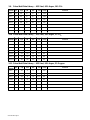
3-9. Pulse Weld Data Library – .035 Steel, 90% Argon, 10% CO2 22. . . . . . . . . . . . . . . . . . . . . . . . .
3-10. Pulse Weld Data Library – .035 Steel, 98% Argon, 2% CO2 22. . . . . . . . . . . . . . . . . . . . . . . . . .
3-11. Pulse Weld Data Library – .035 Steel, 98% Argon, 2% Oxygen 22. . . . . . . . . . . . . . . . . . . . . . .
3-12. Pulse Weld Data Library – .045 Steel, 90% Argon, 10% CO2 23. . . . . . . . . . . . . . . . . . . . . . . . .
3-13. Pulse Weld Data Library – .045 Steel, 98% Argon, 2% CO2 23. . . . . . . . . . . . . . . . . . . . . . . . . .
3-14. Pulse Weld Data Library – .045 Steel, 98% Argon, 2% Oxygen 23. . . . . . . . . . . . . . . . . . . . . . .
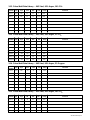
3-15. Pulse Weld Data Library – .052 Steel, 90% Argon, 10% CO2 23. . . . . . . . . . . . . . . . . . . . . . . . .
3-16. Pulse Weld Data Library – .052 Steel, 98% Argon, 2% CO2 24. . . . . . . . . . . . . . . . . . . . . . . . . .
3-17. Pulse Weld Data Library – .052 Steel, 98% Argon, 2% Oxygen 24. . . . . . . . . . . . . . . . . . . . . . .
3-18. Pulse Weld Data Library – .062 Steel, 90% Argon, 10% CO2 24. . . . . . . . . . . . . . . . . . . . . . . . .
3-19. Pulse Weld Data Library – .062 Steel, 98% Argon, 2% CO2 24. . . . . . . . . . . . . . . . . . . . . . . . . .
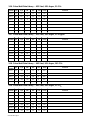
3-20. Pulse Weld Data Library – .062 Steel, 98% Argon, 2% Oxygen 25. . . . . . . . . . . . . . . . . . . . . . .
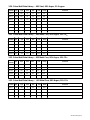
3-21. Pulse Weld Data Library – .045 Metal Core, 90% Argon, 10% CO2 25. . . . . . . . . . . . . . . . . . . .
3-22. Pulse Weld Data Library – .052 Metal Core, 90% Argon, 10% CO2 25. . . . . . . . . . . . . . . . . . . .
3-23. Pulse Weld Data Library – .062 Metal Core, 90% Argon, 10% CO2 25. . . . . . . . . . . . . . . . . . .
3-24. Set Value Mode 26. . . . . . . . . . . . . . . . . . . . . . . . . . . . . . . . . . . . . . . . . . . . . . . . . . . . . . . . . . . . . . .
SECTION 4 – SAFETY PRECAUTIONS FOR SERVICING 27. . . . . . . . . . . . . . . . . . . . . . . . . . . . . . . . . . .
4-1. Symbol Usage 27. . . . . . . . . . . . . . . . . . . . . . . . . . . . . . . . . . . . . . . . . . . . . . . . . . . . . . . . . . . . . . . .
4-2. Servicing Hazards 27. . . . . . . . . . . . . . . . . . . . . . . . . . . . . . . . . . . . . . . . . . . . . . . . . . . . . . . . . . . .
4-3. EMF Information 28. . . . . . . . . . . . . . . . . . . . . . . . . . . . . . . . . . . . . . . . . . . . . . . . . . . . . . . . . . . . . .
WARNING
This product, when used
for welding or cutting,
produces fumes or
gases which contain
chemicals known to the
State of California to
cause birth defects and,
in some cases, cancer.
(California Health &
Safety Code Section
25249.5 et seq.)
OM–210 540

TABLE OF CONTENTS
SECTION 5 – MAINTENANCE & TROUBLESHOOTING 29. . . . . . . . . . . . . . . . . . . . . . . . . . . . . . . . . . . .
5-1. Routine Maintenance 29. . . . . . . . . . . . . . . . . . . . . . . . . . . . . . . . . . . . . . . . . . . . . . . . . . . . . . . . . .
5-2. Blowing Out Inside Of Unit 29. . . . . . . . . . . . . . . . . . . . . . . . . . . . . . . . . . . . . . . . . . . . . . . . . . . . . .
5-3. Front Panel Error Messages 30. . . . . . . . . . . . . . . . . . . . . . . . . . . . . . . . . . . . . . . . . . . . . . . . . . . .
5-4. Removing Cover and Measuring Input Capacitor Voltage 31. . . . . . . . . . . . . . . . . . . . . . . . . . . .
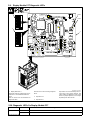
5-5. Weld Process Board PC4 Diagnostic LED’s 32. . . . . . . . . . . . . . . . . . . . . . . . . . . . . . . . . . . . . . .
5-6. Diagnostic LED’s On Process Board PC4 32. . . . . . . . . . . . . . . . . . . . . . . . . . . . . . . . . . . . . . . . .
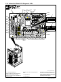
5-7. Motor Board PC6 Diagnostic LED’s And Dip Switch Settings 33. . . . . . . . . . . . . . . . . . . . . . . . .
5-8. Diagnostic LED’s On Motor Board PC6 33. . . . . . . . . . . . . . . . . . . . . . . . . . . . . . . . . . . . . . . . . . .
5-9. Display Module PC7 Diagnostic LED’s 34. . . . . . . . . . . . . . . . . . . . . . . . . . . . . . . . . . . . . . . . . . . .
5-10. Diagnostic LED’s On Display Module PC7 34. . . . . . . . . . . . . . . . . . . . . . . . . . . . . . . . . . . . . . . .
5-11. Automation Module PC9 Diagnostic LED’s 35. . . . . . . . . . . . . . . . . . . . . . . . . . . . . . . . . . . . . . . .
5-12. Diagnostic LED’s On Automation Module PC9 36. . . . . . . . . . . . . . . . . . . . . . . . . . . . . . . . . . . . .
5-13. Network Status Table 37. . . . . . . . . . . . . . . . . . . . . . . . . . . . . . . . . . . . . . . . . . . . . . . . . . . . . . . . . .
5-14. Robot Calibration Mode 38. . . . . . . . . . . . . . . . . . . . . . . . . . . . . . . . . . . . . . . . . . . . . . . . . . . . . . . .
5-15. Robot Override Mode 39. . . . . . . . . . . . . . . . . . . . . . . . . . . . . . . . . . . . . . . . . . . . . . . . . . . . . . . . . .
5-16. Troubleshooting 40. . . . . . . . . . . . . . . . . . . . . . . . . . . . . . . . . . . . . . . . . . . . . . . . . . . . . . . . . . . . . .
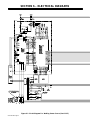
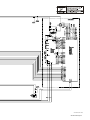
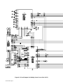
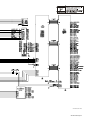
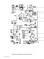
SECTION 6 – ELECTRICAL DIAGRAMS 42. . . . . . . . . . . . . . . . . . . . . . . . . . . . . . . . . . . . . . . . . . . . . . . . .
SECTION 7 – PARTS LIST 56. . . . . . . . . . . . . . . . . . . . . . . . . . . . . . . . . . . . . . . . . . . . . . . . . . . . . . . . . . . . . .
WARRANTY

OM-210 540 Page 1
SECTION 1 – SAFETY PRECAUTIONS - READ BEFORE USING
som _nd_4/98
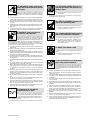
1-1. Symbol Usage
Means Warning! Watch Out! There are possible hazards
with this procedure! The possible hazards are shown in
the adjoining symbols.
Y Marks a special safety message.
. Means “Note”; not safety related.
This group of symbols means Warning! Watch Out! possible
ELECTRIC SHOCK, MOVING PARTS, and HOT PARTS hazards.
Consult symbols and related instructions below for necessary actions
to avoid the hazards.
1-2. Arc Welding Hazards
Y The symbols shown below are used throughout this manual to
call attention to and identify possible hazards. When you see
the symbol, watch out, and follow the related instructions to
avoid the hazard. The safety information given below is only
a summary of the more complete safety information found in
the Safety Standards listed in Section 1-4. Read and follow all
Safety Standards.
Y Only qualified persons should install, operate, maintain, and
repair this unit.
Y During operation, keep everybody, especially children, away.
ELECTRIC SHOCK can kill.
Touching live electrical parts can cause fatal shocks
or severe burns. The electrode and work circuit is
electrically live whenever the output is on. The input
power circuit and machine internal circuits are also
live when power is on. In semiautomatic or automatic wire welding, the
wire, wire reel, drive roll housing, and all metal parts touching the
welding wire are electrically live. Incorrectly installed or improperly
grounded equipment is a hazard.
D Do not touch live electrical parts.
D Wear dry, hole-free insulating gloves and body protection.
D Insulate yourself from work and ground using dry insulating mats
or covers big enough to prevent any physical contact with the work
or ground.
D Do not use AC output in damp areas, if movement is confined, or if
there is a danger of falling.
D Use AC output ONLY if required for the welding process.
D If AC output is required, use remote output control if present on
unit.
D Disconnect input power or stop engine before installing or
servicing this equipment. Lockout/tagout input power according to
OSHA 29 CFR 1910.147 (see Safety Standards).
D Properly install and ground this equipment according to its
Owner’s Manual and national, state, and local codes.
D Always verify the supply ground – check and be sure that input
power cord ground wire is properly connected to ground terminal in
disconnect box or that cord plug is connected to a properly
grounded receptacle outlet.
D When making input connections, attach proper grounding conduc-
tor first – double-check connections.
D Frequently inspect input power cord for damage or bare wiring –
replace cord immediately if damaged – bare wiring can kill.
D Turn off all equipment when not in use.
D Do not use worn, damaged, undersized, or poorly spliced cables.
D Do not drape cables over your body.
D If earth grounding of the workpiece is required, ground it directly
with a separate cable.
D Do not touch electrode if you are in contact with the work, ground,
or another electrode from a different machine.
D Use only well-maintained equipment. Repair or replace damaged
parts at once. Maintain unit according to manual.
D Wear a safety harness if working above floor level.
D Keep all panels and covers securely in place.
D Clamp work cable with good metal-to-metal contact to workpiece
or worktable as near the weld as practical.
D Insulate work clamp when not connected to workpiece to prevent
contact with any metal object.
D Do not connect more than one electrode or work cable to any
single weld output terminal.
SIGNIFICANT DC VOLTAGE exists after removal of
input power on inverters.
D Turn Off inverter, disconnect input power, and discharge input
capacitors according to instructions in Maintenance Section
before touching any parts.
Welding produces fumes and gases. Breathing
these fumes and gases can be hazardous to your
health.
FUMES AND GASES can be hazardous.
D Keep your head out of the fumes. Do not breathe the fumes.
D If inside, ventilate the area and/or use exhaust at the arc to remove
welding fumes and gases.
D If ventilation is poor, use an approved air-supplied respirator.
D Read the Material Safety Data Sheets (MSDSs) and the
manufacturer’s instructions for metals, consumables, coatings,
cleaners, and degreasers.
D Work in a confined space only if it is well ventilated, or while
wearing an air-supplied respirator. Always have a trained watch-
person nearby. Welding fumes and gases can displace air and
lower the oxygen level causing injury or death. Be sure the breath-
ing air is safe.
D Do not weld in locations near degreasing, cleaning, or spraying op-
erations. The heat and rays of the arc can react with vapors to form
highly toxic and irritating gases.
D Do not weld on coated metals, such as galvanized, lead, or
cadmium plated steel, unless the coating is removed from the weld
area, the area is well ventilated, and if necessary, while wearing an
air-supplied respirator. The coatings and any metals containing
these elements can give off toxic fumes if welded.

OM-210 540 Page 2
Arc rays from the welding process produce intense
visible and invisible (ultraviolet and infrared) rays
that can burn eyes and skin. Sparks fly off from the
weld.
ARC RAYS can burn eyes and skin.
D Wear a welding helmet fitted with a proper shade of filter to protect
your face and eyes when welding or watching (see ANSI Z49.1
and Z87.1 listed in Safety Standards).
D Wear approved safety glasses with side shields under your
helmet.
D Use protective screens or barriers to protect others from flash and
glare; warn others not to watch the arc.
D Wear protective clothing made from durable, flame-resistant mate-
rial (leather and wool) and foot protection.
Welding on closed containers, such as tanks,
drums, or pipes, can cause them to blow up. Sparks
can fly off from the welding arc. The flying sparks, hot
workpiece, and hot equipment can cause fires and
burns. Accidental contact of electrode to metal objects can cause
sparks, explosion, overheating, or fire. Check and be sure the area is
safe before doing any welding.
WELDING can cause fire or explo-
sion.
D Protect yourself and others from flying sparks and hot metal.
D Do not weld where flying sparks can strike flammable material.
D Remove all flammables within 35 ft (10.7 m) of the welding arc. If
this is not possible, tightly cover them with approved covers.
D Be alert that welding sparks and hot materials from welding can
easily go through small cracks and openings to adjacent areas.
D Watch for fire, and keep a fire extinguisher nearby.
D Be aware that welding on a ceiling, floor, bulkhead, or partition can
cause fire on the hidden side.
D Do not weld on closed containers such as tanks, drums, or pipes,
unless they are properly prepared according to AWS F4.1 (see
Safety Standards).
D Connect work cable to the work as close to the welding area as
practical to prevent welding current from traveling long, possibly
unknown paths and causing electric shock and fire hazards.
D Do not use welder to thaw frozen pipes.
D Remove stick electrode from holder or cut off welding wire at
contact tip when not in use.
D Wear oil-free protective garments such as leather gloves, heavy
shirt, cuffless trousers, high shoes, and a cap.
D Remove any combustibles, such as a butane lighter or matches,
from your person before doing any welding.
FLYING METAL can injure eyes.
D Welding, chipping, wire brushing, and grinding
cause sparks and flying metal. As welds cool,
they can throw off slag.
D Wear approved safety glasses with side
shields even under your welding helmet.
BUILDUP OF GAS can injure or kill.
D Shut off shielding gas supply when not in use.
D Always ventilate confined spaces or use
approved air-supplied respirator.
HOT PARTS can cause severe burns.
D Do not touch hot parts bare handed.
D Allow cooling period before working on gun or
torch.
MAGNETIC FIELDS can affect pacemak-
ers.
D Pacemaker wearers keep away.
D Wearers should consult their doctor before
going near arc welding, gouging, or spot
welding operations.
NOISE can damage hearing.
Noise from some processes or equipment can
damage hearing.
D Wear approved ear protection if noise level is
high.
Shielding gas cylinders contain gas under high
pressure. If damaged, a cylinder can explode. Since
gas cylinders are normally part of the welding
process, be sure to treat them carefully.
CYLINDERS can explode if damaged.
D Protect compressed gas cylinders from excessive heat, mechani-
cal shocks, slag, open flames, sparks, and arcs.
D Install cylinders in an upright position by securing to a stationary
support or cylinder rack to prevent falling or tipping.
D Keep cylinders away from any welding or other electrical circuits.
D Never drape a welding torch over a gas cylinder.
D Never allow a welding electrode to touch any cylinder.
D Never weld on a pressurized cylinder – explosion will result.
D Use only correct shielding gas cylinders, regulators, hoses, and fit-
tings designed for the specific application; maintain them and
associated parts in good condition.
D Turn face away from valve outlet when opening cylinder valve.
D Keep protective cap in place over valve except when cylinder is in
use or connected for use.
D Read and follow instructions on compressed gas cylinders,
associated equipment, and CGA publication P-1 listed in Safety
Standards.

OM-210 540 Page 3
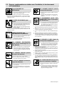
1-3. Additional Symbols For Installation, Operation, And Maintenance
FIRE OR EXPLOSION hazard.
D Do not install or place unit on, over, or near
combustible surfaces.
D Do not install unit near flammables.
D Do not overload building wiring – be sure power supply system is
properly sized, rated, and protected to handle this unit.
FALLING UNIT can cause injury.
D Use lifting eye to lift unit only, NOT running
gear, gas cylinders, or any other accessories.
D Use equipment of adequate capacity to lift and
support unit.
D If using lift forks to move unit, be sure forks are
long enough to extend beyond opposite side of
unit.
OVERUSE can cause OVERHEATING
D Allow cooling period; follow rated duty cycle.
D Reduce current or reduce duty cycle before
starting to weld again.
D Do not block or filter airflow to unit.
STATIC (ESD) can damage PC boards.
D Put on grounded wrist strap BEFORE handling
boards or parts.
D Use proper static-proof bags and boxes to
store, move, or ship PC boards.
MOVING PARTS can cause injury.
D Keep away from moving parts.
D Keep away from pinch points such as drive
rolls.
WELDING WIRE can cause injury.
D Do not press gun trigger until instructed to do
so.
D Do not point gun toward any part of the body,
other people, or any metal when threading
welding wire.
MOVING PARTS can cause injury.
D Keep away from moving parts such as fans.
D Keep all doors, panels, covers, and guards
closed and securely in place.
H.F. RADIATION can cause interference.
D High-frequency (H.F.) can interfere with radio
navigation, safety services, computers, and
communications equipment.
D Have only qualified persons familiar with
electronic equipment perform this installation.
D The user is responsible for having a qualified electrician prompt-
ly correct any interference problem resulting from the installa-
tion.
D If notified by the FCC about interference, stop using the
equipment at once.
D Have the installation regularly checked and maintained.
D Keep high-frequency source doors and panels tightly shut, keep
spark gaps at correct setting, and use grounding and shielding to
minimize the possibility of interference.
ARC WELDING can cause interference.
D Electromagnetic energy can interfere with
sensitive electronic equipment such as
computers and computer-driven equipment
such as robots.
D Be sure all equipment in the welding area is
electromagnetically compatible.
D To reduce possible interference, keep weld cables as short as
possible, close together, and down low, such as on the floor.
D Locate welding operation 100 meters from any sensitive elec-
tronic equipment.
D Be sure this welding machine is installed and grounded
according to this manual.
D If interference still occurs, the user must take extra measures
such as moving the welding machine, using shielded cables,
using line filters, or shielding the work area.
1-4. Principal Safety Standards
Safety in Welding and Cutting, ANSI Standard Z49.1, from American
Welding Society, 550 N.W. LeJeune Rd, Miami FL 33126
Safety and Health Standards, OSHA 29 CFR 1910, from Superinten-
dent of Documents, U.S. Government Printing Office, Washington, D.C.
20402.
Recommended Safe Practices for the Preparation for Welding and Cut-
ting of Containers That Have Held Hazardous Substances, American
Welding Society Standard AWS F4.1, from American Welding Society,
550 N.W. LeJeune Rd, Miami, FL 33126
National Electrical Code, NFPA Standard 70, from National Fire Protec-
tion Association, Batterymarch Park, Quincy, MA 02269.
Safe Handling of Compressed Gases in Cylinders, CGA Pamphlet P-1,
from Compressed Gas Association, 1235 Jefferson Davis Highway,
Suite 501, Arlington, VA 22202.
Code for Safety in Welding and Cutting, CSA Standard W117.2, from
Canadian Standards Association, Standards Sales, 178 Rexdale
Boulevard, Rexdale, Ontario, Canada M9W 1R3.
Safe Practices For Occupation And Educational Eye And Face
Protection, ANSI Standard Z87.1, from American National Standards
Institute, 1430 Broadway, New York, NY 10018.
Cutting And Welding Processes, NFPA Standard 51B, from National
Fire Protection Association, Batterymarch Park, Quincy, MA 02269.

OM-210 540 Page 4
1-5. EMF Information
Considerations About Welding And The Effects Of Low Frequency
Electric And Magnetic Fields
Welding current, as it flows through welding cables, will cause electro-
magnetic fields. There has been and still is some concern about such
fields. However, after examining more than 500 studies spanning 17
years of research, a special blue ribbon committee of the National
Research Council concluded that: “The body of evidence, in the
committee’s judgment, has not demonstrated that exposure to power-
frequency electric and magnetic fields is a human-health hazard.”
However, studies are still going forth and evidence continues to be
examined. Until the final conclusions of the research are reached, you
may wish to minimize your exposure to electromagnetic fields when
welding or cutting.
To reduce magnetic fields in the workplace, use the following
procedures:
1. Keep cables close together by twisting or taping them.
2. Arrange cables to one side and away from the operator.
3. Do not coil or drape cables around your body.
4. Keep welding power source and cables as far away from opera-
tor as practical.
5. Connect work clamp to workpiece as close to the weld as possi-
ble.
About Pacemakers:
Pacemaker wearers consult your doctor first. If cleared by your doctor,
then following the above procedures is recommended.

OM-210 540 Page 5
SECTION 1 – CONSIGNES DE SECURITE – LIRE AVANT
UTILISATION
som _nd_fre 4/98
1-1. Signification des symboles
Signifie Mise en garde ! Soyez vigilant ! Cette procédure
présente des risques de danger ! Ceux-ci sont identifiés
par des symboles adjacents aux directives.
Y Identifie un message de sécurité particulier.
. Signifie NOTA ; n’est pas relatif à la sécurité.
Ce groupe de symboles signifie Mise en garde ! Soyez vigilant ! Il y a des
risques de danger reliés aux CHOCS ÉLECTRIQUES, aux PIÈCES EN
MOUVEMENT et aux PIÈCES CHAUDES. Reportez-vous aux symboles
et aux directives ci-dessous afin de connaître les mesures à prendre pour
éviter tout danger.
1-2. Dangers relatifs au soudage à l’arc
Y Les symboles présentés ci-après sont utilisés tout au long du
présent manuel pour attirer votre attention et identifier les risques
de danger. Lorsque vous voyez un symbole, soyez vigilant et
suivez les directives mentionnées afin d’éviter tout danger. Les
consignes de sécurité présentées ci-après ne font que résumer
l’information contenue dans les normes de sécurité énumérées
à la section 1-4. Veuillez lire et respecter toutes ces normes de
sécurité.
Y L’installation, l’utilisation, l’entretien et les réparations ne doi-
vent être confiés qu’à des personnes qualifiées.
Y Au cours de l’utilisation, tenir toute personne à l’écart et plus par-
ticulièrement les enfants.
UN CHOC ÉLECTRIQUE peut tuer.
Un simple contact avec des pièces électriques peut
provoquer une électrocution ou des blessures graves.
L’électrode et le circuit de soudage sont sous tension
dès que l’appareil est sur ON. Le circuit d’entrée et les
circuits internes de l’appareil sont également sous
tension à ce moment-là. En soudage semi-automatique ou automatique,
le fil, le dévidoir, le logement des galets d’entraînement et les pièces
métalliques en contact avec le fil de soudage sont sous tension. Des
matériels mal installés ou mal mis à la terre présentent un danger.
D Ne jamais toucher les pièces électriques sous tension.
D Porter des gants et des vêtements de protection secs ne comportant
pas de trous.
D S’isoler de la pièce et de la terre au moyen de tapis ou d’autres
moyens isolants suffisamment grands pour empêcher le contact phy-
sique éventuel avec la pièce ou la terre.
D Ne pas se servir de source électrique àcourant électrique dans les zones
humides, dans les endroits confinés ou là où on risque de tomber.
D Se servir d’une source électrique àcourant électrique UNIQUEMENT si le
procédé de soudage le demande.
D Si l’utilisation d’une source électrique àcourant électrique s’avère néces-
saire, se servir de la fonction de télécommande si l’appareil en est équipé.
D Couper l’alimentation ou arrêter le moteur avant de procéder à l’instal-
lation, à la réparation ou à l’entretien de l’appareil. Déverrouiller
l’alimentation selon la norme OSHA 29 CFR 1910.147 (voir normes de
sécurité).
D Installer et mettre à la terre correctement cet appareil conformément à
son manuel d’utilisation et aux codes nationaux, provinciaux et
municipaux.
D Toujours vérifier la terre du cordon d’alimentation – Vérifier et s’assu-
rer que le fil de terre du cordon d’alimentation est bien raccordé à la
borne de terre du sectionneur ou que la fiche du cordon est raccordée
à une prise correctement mise à la terre.
D En effectuant les raccordements d’entrée fixer d’abord le conducteur
de mise à la terre approprié et contre-vérifier les connexions.
D Vérifier fréquemment le cordon d’alimentation pour voir s’il n’est pas
endommagé ou dénudé – remplacer le cordon immédiatement s’il est
endommagé – un câble dénudé peut provoquer une électrocution.
D Mettre l’appareil hors tension quand on ne l’utilise pas.
D Ne pas utiliser des câbles usés, endommagés, de grosseur insuffi-
sante ou mal épissés.
D Ne pas enrouler les câbles autour du corps.
D Si la pièce soudée doit être mise à la terre, le faire directement avec un
câble distinct.
D Ne pas toucher l’électrode quand on est en contact avec la pièce, la
terre ou une électrode provenant d’une autre machine.
D N’utiliser qu’un matériel en bon état. Réparer ou remplacer sur-le-
champ les pièces endommagées. Entretenir l’appareil conformément
à ce manuel.
D Porter un harnais de sécurité quand on travaille en hauteur.
D Maintenir solidement en place tous les panneaux et capots.
D Fixer le câble de retour de façon à obtenir un bon contact métal-métal
avec la pièce à souder ou la table de travail, le plus près possible de la
soudure.
D Isoler la pince de masse quand pas mis à la pièce pour éviter le contact
avec tout objet métallique.
Il y a DU COURANT CONTINU IMPORTANT dans les
convertisseurs après la suppression de l’alimenta-
tion électrique.
D Arrêter les convertisseurs, débrancher le courant électrique, et dé-
charger les condensateurs d’alimentation selon les instructions
indiquées dans la partie entretien avant de toucher les pièces.
Le soudage génère des fumées et des gaz. Leur
inhalation peut être dangereux pour votre santé.
D Eloigner votre tête des fumées. Ne pas respirer
les fumées.
D A l’intérieur, ventiler la zone et/ou utiliser un échappement au niveau
de l’arc pour l’évacuation des fumées et des gaz de soudage.
D Si la ventilation est insuffisante, utiliser un respirateur à alimenta-
tion d’air homologué.
D Lire les spécifications de sécurité des matériaux (MSDSs) et les
instructions du fabricant concernant les métaux, les consomma-
bles, les revêtements, les nettoyants et les dégraisseurs.
D Travailler dans un espace fermé seulement s’il est bien ventilé ou en
portant un respirateur à alimentation d’air. Demander toujours à un
surveillant dûment formé de se tenir à proximité. Des fumées et des
gaz de soudage peuvent déplacer l’air et abaisser le niveau d’oxy-
gène provoquant des blessures ou des accidents mortels. S’assu-
rer que l’air de respiration ne présente aucun danger.
D Ne pas souder dans des endroits situés à proximité d’opérations de
dégraissage, de nettoyage ou de pulvérisation. La chaleur et les
rayons de l’arc peuvent réagir en présence de vapeurs et former des
gaz hautement toxiques et irritants.
D Ne pas souder des métaux munis d’un revêtement, tels que l’acier
galvanisé, plaqué en plomb ou au cadmium à moins que le revête-
ment n’ait été enlevé dans la zone de soudure, que l’endroit soit bien
ventilé, et si nécessaire, en portant un respirateur à alimentation
d’air. Les revêtements et tous les métaux renfermant ces éléments
peuvent dégager des fumées toxiques en cas de soudage.
LES FUMÉES ET LES GAZ peuvent
être dangereux.

OM-210 540 Page 6
Le rayonnement de l’arc du procédé de soudage
génère des rayons visibles et invisibles intenses
(ultraviolets et infrarouges) susceptibles de provoquer
des brûlures dans les yeux et sur la peau. Des étincelles sont projetées
pendant le soudage.
LES RAYONS DE L’ARC peuvent pro-
voquer des brûlures dans les yeux et
sur la peau.
D Porter un casque de soudage muni d’un écran de filtre approprié pour
protéger votre visage et vos yeux pendant le soudage ou pour regar-
der (voir ANSI Z49.1 et Z87.1 énuméré dans les normes de sécurité).
D Porter des protections approuvés pour les oreilles si le niveau sondre est
trop élevé.
D Utiliser des écrans ou des barrières pour protéger des tiers de l’éclair
et de l’éblouissement; demander aux autres personnes de ne pas re-
garder l’arc.
D Porter des vêtements de protection constitué dans une matière dura-
ble, résistant au feu (cuir ou laine) et une protection des pieds.
Le soudage effectué sur des conteneurs fermés tels
que des réservoirs, tambours ou des conduites peut
provoquer leur éclatement. Des étincelles peuvent être
projetées de l’arc de soudure. La projection d’étincel-
les, des pièces chaudes et des équipements chauds peut provoquer des
incendies et des brûlures. Le contact accidentel de l’électrode avec des
objets métalliques peut provoquer des étincelles, une explosion, un
surchauffement ou un incendie. Avant de commencer le soudage, vérifier
et s’assurer que l’endroit ne présente pas de danger.
LE SOUDAGE peut provoquer un
incendie ou une explosion.
D Se protéger et d’autres personnes de la projection d’étincelles et de
métal chaud.
D Ne pas souder dans un endroit là où des étincelles peuvent tomber sur
des substances inflammables.
D Déplacer toutes les substances inflammables à une distance de 10,7
m de l’arc de soudage. En cas d’impossibilité les recouvrir soigneuse-
ment avec des protections homologués.
D Des étincelles et des matériaux chauds du soudage peuvent facile-
ment passer dans d’autres zones en traversant de petites fissures et
des ouvertures.
D Surveiller tout déclenchement d’incendie et tenir un extincteur à proxi-
mité.
D Le soudage effectué sur un plafond, plancher, paroi ou séparation
peut déclencher un incendie de l’autre côté.
D Ne pas effectuer le soudage sur des conteneurs fermés tels que des
réservoirs, tambours, ou conduites, à moins qu’ils n’aient été prépa-
rés correctement conformément à AWS F4.1 (voir les normes de
sécurité).
D Brancher le câble sur la pièce le plus près possible de la zone de sou-
dage pour éviter le transport du courant sur une longue distance par
des chemins inconnus éventuels en provoquant des risques d’élec-
trocution et d’incendie.
D Ne pas utiliser le poste de soudage pour dégeler des conduites ge-
lées.
D En cas de non utilisation, enlever la baguette d’électrode du porte-
électrode ou couper le fil à la pointe de contact.
D Porter des vêtements de protection dépourvus d’huile tels que des
gants en cuir, une chemise en matériau lourd, des pantalons sans re-
vers, des chaussures hautes et un couvre chef.
D Avant de souder, retirer toute substance combustible de vos poches
telles qu’un allumeur au butane ou des allumettes.
DES PARTICULES VOLANTES
peuvent blesser les yeux.
D Le soudage, l’écaillement, le passage de la pièce
à la brosse en fil de fer, et le meulage génèrent
des étincelles et des particules métalliques vo-
lantes. Pendant la période de refroidissement des soudures, elles ris-
quent de projeter du laitier.
D Porter des lunettes de sécurité avec écrans latéraux ou un écran facial.
LES ACCUMULATIONS DE GAZ ris-
quent de provoquer des blessures ou
même la mort.
D Fermer l’alimentation du gaz protecteur en cas de
non utilisation.
D Veiller toujours à bien aérer les espaces confinés ou se servir d’un respi-
rateur d’adduction d’air homologué.
DES PIÈCES CHAUDES peuvent pro-
voquer des brûlures graves.
D Ne pas toucher des parties chaudes à mains nues
D Prévoir une période de refroidissement avant
d’utiliser le pistolet ou la torche.
LES CHAMPS MAGNÉTIQUES peuvent
affecter les stimulateurs cardiaques.
D Porteurs de stimulateur cardiaque, restez à distance.
D Les porteurs d’un stimulateur cardiaque doivent
d’abord consulter leur médecin avant de s’approcher
des opérations de soudage à l’arc, de gougeage ou
de soudage par points.
LE BRUIT peut affecter l’ouïe.
Le bruit des processus et des équipements peut affecter
l’ouïe.
D Porter des protections approuvés pour les oreilles si
le niveau sondre est trop élevé.
Des bouteilles de gaz protecteur contiennent du gaz
sous haute pression. Si une bouteille est endomma-
gée, elle peut exploser. Du fait que les bouteilles de gaz
font normalement partie du procédé de soudage, les
manipuler avec précaution.
D Protéger les bouteilles de gaz comprimé d’une chaleur excessive,
des chocs mécaniques, du laitier, des flammes ouvertes, des étin-
celles et des arcs.
D Placer les bouteilles debout en les fixant dans un support stationnai-
re ou dans un porte-bouteilles pour les empêcher de tomber ou de
se renverser.
D Tenir les bouteilles éloignées des circuits de soudage ou autres cir-
cuits électriques.
D Ne jamais placer une torche de soudage sur une bouteille à gaz.
D Une électrode de soudage ne doit jamais entrer en contact avec une
bouteille.
D Ne jamais souder une bouteille pressurisée – risque d’explosion.
D Utiliser seulement des bouteilles de gaz protecteur, régulateurs,
tuyaux et raccords convenables pour cette application spécifique;
les maintenir ainsi que les éléments associés en bon état.
D Ne pas tenir la tête en face de la sortie en ouvrant la soupape de la
bouteille.
D Maintenir le chapeau de protection sur la soupape, sauf en cas d’uti-
lisation ou de branchement de la bouteille.
D Lire et suivre les instructions concernant les bouteilles de gaz com-
primé, les équipements associés et les publications P-1 CGA énu-
mérées dans les normes de sécurité.
Si des BOUTEILLES sont endomma-
gées, elles pourront exploser.

OM-210 540 Page 7
1-3. Dangers supplémentaires en relation avec l’installation, le fonctionnement
et la maintenance
Risque D’INCENDIE OU
D’EXPLOSION.
D Ne pas placer l’appareil sur, au-dessus ou à proxi-
mité de surfaces infllammables.
D Ne pas installer l’appareil à proximité de produits inflammables
D Ne pas surcharger l’installation électrique – s”assurer que l’alimen-
tation est correctement dimensionné et protégé avant de mettre
l’appareil en service.
LA CHUTE DE L’APPAREIL peut
blesser.
D Utiliser l’anneau de levage uniquement pour sou-
lever l’appareil, NON PAS les chariot, les bouteil-
les de gaz ou tout autre accessoire.
D Utiliser un engin d’une capacité appropriée pour
soulever l’appareil.
D En utilisant des fourches de levage pour déplacer l’unité, s’assurer
que les fourches sont suffisamment longues pour dépasser du côté
opposé de l’appareil.
L’EMPLOI EXCESSIF peut
SURCHAUFFER L’ÉQUIPEMENT.
D Prévoir une période de refroidissement, respec-
ter le cycle opératoire nominal.
D Réduire le courant ou le cycle opératoire avant de
recommancer le soudage.
D Ne pas obstruer les passages d’air du poste.
LES CHARGES ÉLECTROSTATI-
QUES peuvent endommager les cir-
cuits imprimés.
D Établir la connexion avec la barrette de terre
avant de manipuler des cartes ou des pièces.
D Utiliser des pochettes et des boîtes antistatiques
pour stocker, déplacer ou expédier des cartes de
circuits imprimes.
DES ORGANES MOBILES peuvent
provoquer des blessures.
D Ne pas s’approcher des organes mobiles.
D Ne pas s’approcher des points de coincement
tels que des rouleaux de commande.
LES FILS DE SOUDAGE peuvent pro-
voquer des blessures.
D Ne pas appuyer sur la gachette avant d’en avoir
reçu l’instruction.
D Ne pas diriger le pistolet vers soi, d’autres person-
nes ou toute pièce mécanique en engageant le fil
de soudage.
DES ORGANES MOBILES peuvent
provoquer des blessures.
D Rester à l’écart des organes mobiles comme le
ventilateur.
D Maintenir fermés et fixement en place les portes,
panneaux, recouvrements et dispositifs de
protection.
LE RAYONNEMENT HAUTE FRÉ-
QUENCE (H.F.) risque de provoquer
des interférences.
D Le rayonnement haute frequence peut provoquer
des interférences avec les équipements de ra-
dio–navigation et de communication, les services
de sécurité et les ordinateurs.
D Demander seulement à des personnes qualifiées familiarisées
avec des équipements électroniques de faire fonctionner l’installa-
tion.
D L’utilisateur est tenu de faire corriger rapidement par un électricien
qualifié les interférences résultant de l’installation.
D Si le FCC signale des interférences, arrêter immédiatement l’appa-
reil.
D Effectuer régulièrement le contrôle et l’entretien de l’installation.
D Maintenir soigneusement fermés les portes et les panneaux des
sources de haute fréquence, maintenir les éclateurs à une distance
correcte et utiliser une terre et et un blindage pour réduire les interfé-
rences éventuelles.
LE SOUDAGE À L’ARC risque de
provoquer des interférences.
D L’énergie électromagnétique risque de provoquer
des interférences pour l’équipement électronique
sensible tel que les ordinateurs et l’équipement
commandé par ordinateur tel que les robots.
D Veiller à ce que tout l’équipement de la zone de soudage soit com-
patible électromagnétiquement.
D Pour réduire la possibilité d’interférence, maintenir les câbles de
soudage aussi courts que possible, les grouper, et les poser aussi
bas que possible (ex. par terre).
D Veiller à souder à une distance de 100 mètres de tout équipement
électronique sensible.
D Veiller à ce que ce poste de soudage soit posé et mis à la terre
conformément à ce mode d’emploi.
D En cas d’interférences après avoir pris les mesures précédentes, il
incombe à l’utilisateur de prendre des mesures supplémentaires tel-
les que le déplacement du poste, l’utilisation de câbles blindés, l’uti-
lisation de filtres de ligne ou la pose de protecteurs dans la zone de
travail.
LES CHAMPS MAGNÉTIQUES peuvent
affecter les stimulateurs cardiaques.
D Porteurs de stimulateur cardiaque, restez à dis-
tance.
D Les porteurs d’un stimulateur cardiaque doivent
d’abord consulter leur médecin avant de s’appro-
cher des opérations de soudage à l’arc, de gou-
geage ou de soudage par points.

OM-210 540 Page 8
1-4. Principales normes de sécurité
Safety in Welding and Cutting, norme ANSI Z49.1, de l’American Wel-
ding Society, 550 N.W. Lejeune Rd, Miami FL 33126
Safety and Health Sandards, OSHA 29 CFR 1910, du Superintendent
of Documents, U.S. Government Printing Office, Washington, D.C.
20402.
Recommended Safe Practice for the Preparation for Welding and Cut-
ting of Containers That Have Held Hazardous Substances, norme AWS
F4.1, de l’American Welding Society, 550 N.W. Lejeune Rd, Miami FL
33126
National Electrical Code, NFPA Standard 70, de la National Fire Protec-
tion Association, Batterymarch Park, Quincy, MA 02269.
Safe Handling of Compressed Gases in Cylinders, CGA Pamphlet P-1,
de la Compressed Gas Association, 1235 Jefferson Davis Highway,
Suite 501, Arlington, VA 22202.
Règles de sécurité en soudage, coupage et procédés connexes, norme
CSA W117.2, de l’Association canadienne de normalisation, vente de
normes, 178 Rexdale Boulevard, Rexdale (Ontario) Canada M9W 1R3.
Safe Practices For Occupation And Educational Eye And Face Protec-
tion, norme ANSI Z87.1, de l’American National Standards Institute,
1430 Broadway, New York, NY 10018.
Cutting and Welding Processes, norme NFPA 51B, de la National Fire
Protection Association, Batterymarch Park, Quincy, MA 02269.
1-5. Information sur les champs électromagnétiques
Données sur le soudage électrique et sur les effets, pour l’organisme,
des champs magnétiques basse fréquence
Le courant de soudage, pendant son passage dans les câbles de sou-
dage, causera des champs électromagnétiques. Il y a eu et il y a encore
un certain souci à propos de tels champs. Cependant, après avoir ex-
aminé plus de 500 études qui ont été faites pendant une période de
recherche de 17 ans, un comité spécial ruban bleu du National Re-
search Council a conclu: “L’accumulation de preuves, suivant le
jugement du comité, n’a pas démontré que l’exposition aux champs
magnétiques et champs électriques à haute fréquence représente un
risque à la santé humaine”. Toutefois, des études sont toujours en cours
et les preuves continuent à être examinées. En attendant que les con-
clusions finales de la recherche soient établies, il vous serait
souhaitable de réduire votre exposition aux champs électromagnéti-
ques pendant le soudage ou le coupage.
Afin de réduire les champs électromagnétiques dans l’environnement
de travail, respecter les consignes suivantes :
1 Garder les câbles ensembles en les torsadant ou en les
attachant avec du ruban adhésif.
2 Mettre tous les câbles du côté opposé de l’opérateur.
3 Ne pas courber pas et ne pas entourer pas les câbles autour de
votre corps.
4 Garder le poste de soudage et les câbles le plus loin possible de
vous.
5 Relier la pince de masse le plus près possible de la zone de
soudure.
Consignes relatives aux stimulateurs cardiaques :
Les personnes qui portent un stimulateur cardiaque doivent avant tout
consulter leur docteur. Si vous êtes déclaré apte par votre docteur, il est
alors recommandé de respecter les consignes ci–dessus.

OM-210 540 Page 9
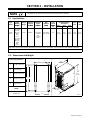
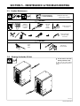
SECTION 2 – INSTALLATION
Appearance of actual unit may vary from unit shown in manual.
NOTE
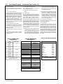
2-1. Specifications
Input
Power
Rated
Welding
Output
Voltage
Range
Amperage
Range In
CC Mode
Wire Feed
Speed
Range**
Wire
Diameter
Range
Max
Open
Circuit
Voltage
Amperes Input At Rated
Load Output 60 Hz,
Three-Phase
Input
kVA
Input
KW
Power
Output
Range
CC Mode
Range**
Range
Voltage
DC
230 V 460 V 575 V
kVA
KW
Three
Phase
230 V input:
400 A @
38 V DC,
100%
Duty
Cycle;
460 V input:
450 A @
38 V DC,
100%
Duty
Cycle
10-44 5-600 A Standard:
50-1400
ipm
(1.3-35.6
mpm)
.030-.062 in
(0.8-1.6 mm)
80 54.0
(0-1A*)
29.0
(0-1A*)
23.0
(0-1A*)
23.8
(0.8*)
22.9
(0.17*)
*While idling; Input amperage fluctuates while idling and is always less than one Ampere. Use one Ampere for power efficiency calculations.
**Wire feed speed ranges are for GMAW welding. While pulse welding, wire feed speed ranges may be more limited.
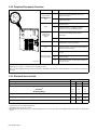
2-2. Dimensions And Weight
Hole Layout Dimensions
A
E
22 in
(559 mm)
A 15-1/8 in (384 mm)
A
22 in
(559 mm)
B 16 in (406 mm)
C 19-3/32 in (485 mm)
28 in
(711 mm)
D 13-5/8 in (346 mm)
B
C
E 11/32 in (9 mm)
Weight
15-1/2 in
(394 mm)
135 lb (61 kg)
D
803 244-A
(394 mm)

OM-210 540 Page 10
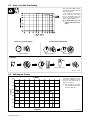
2-3. Duty Cycle And Overheating
Duty Cycle is percentage of 10 min-
utes that unit can weld at rated load
without overheating.
If unit overheats, thermostat(s)
opens, output stops, and cooling
fan runs. Wait fifteen minutes for
unit to cool. Reduce amperage or
duty cycle before welding.
Y Exceeding duty cycle can
damage unit and void war-
ranty.
Overheating
0
15
A/V
OR
Reduce Duty Cycle
Minutes
duty1 4/95 – 181 560
Continuous Welding
100% Duty Cycle At 450 Amperes 60% Duty Cycle At 580 Amperes
6 Minutes Welding 4 Minutes Resting
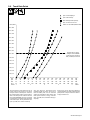
2-4. Volt-Ampere Curves
va_curve1 4/95
Volt-ampere curves show minimum
and maximum voltage and amper-
age output capabilities of unit.
Curves of other settings fall be-
tween curves shown.
. This volt-ampere curve repre-
sents the dynamic output of the
unit with a static load.
CV MODE
0.0
10.0
20.0
30.0
40.0
50.0
60.0
70.0
80.0
0.0 100.0 200.0 300.0 400.0 500.0 600.0 700.0 800.0 900.0
AMPERAGE
VOLTAGE

OM-210 540 Page 11
2-5. Selecting A Location
loc_2 3/96 -803 244-A
Y Do not stack units. Beware of
tipping.
1 Lifting Forks
Use lifting forks to move unit.
Extend forks beyond opposite side
of unit.
2 Hand Cart
Use cart or similar device to move
unit.
3 Rating Label
Use rating label to determine input
power needs.
4 Line Disconnect Device
Locate unit near correct input
power supply.
Movement
2
Location
4
18 in
(460 mm)
18 in
(460 mm)
3
Y Do not move or operate
unit where it could tip.
Tipping
1
OR
Y Special installation may be required where gasoline or volatile
liquids are present – see NEC Article 511 or CEC Section 20.
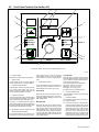
803 244-A / Ref. 801 915-A
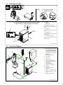
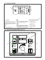
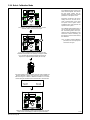
. The proper interface kit must
be installed in the welding pow-
er source/interface unit to allow
it to be connected to the robot.
1 Robot (Will Vary According To
Application)
2 Motor/Drive Assembly
3 Gas Cylinder
4 Gas Hose
5 Robot Control
6 Robot Input/Output Cable
7 Gas And Motor Control Cable
8 Welding Power
Source/Interface Unit
9 Negative (–) Weld Cable
10 Workpiece
11 Voltage Sensing Lead
(Optional)
. Positive (+) voltage sensing
lead is contained in the motor
cable.
12 Positive (+) Weld Cable
1
2 3
4
5
7
6
8
9
10
11
12
2-6. Connection Diagram

OM-210 540 Page 12
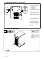
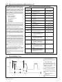
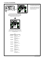
Ref. 803 245-B
1 115 V 10 A AC Receptacle RC2
Receptacle supplies 60 Hz single-
phase power. Maximum output from
RC2 is limited by circuit breaker CB2 to
10 amps.
2 Circuit Breaker CB1
3 Circuit Breaker CB2
CB1 protects 115 volt receptacle RC2
from overload. If CB1 opens, RC2 does
not work.
CB2 protects the wirefeed motor from
overload. If CB2 opens, the wirefeeder
does not work.
. Press button to reset breaker. If
breaker continue to open, contact a
Factory Authorized Service Agent.
4 Wirefeed/Gas Receptacle RC8
Use receptacle to connect gas and mo-
tor control cable to power source (see
Section 2-6).
5 Peripheral Receptacle RC25
Receptacle provides connection to
touch sensor, water flow switch, jog +/–,
and n/o relay contacts circuitry (see
Section 2-10).
6 Robot Interface Receptacle RC72
Use receptacle to connect robot input/
output cable.
2
3
2-7. Rear Panel Receptacles And Circuit Breakers
1
6
4
5
2-8. Connecting To Weld Terminals
Y Turn off power before con-
necting to weld output ter-
minals.
1 Positive (+) Weld Output
Terminal
2 Negative (–) Weld Output
Terminal
Connect positive weld cable to
Positive (+) weld terminal and
negative (–) cable to Negative
weld terminal.
Tools Needed:
803 244-A
1
2
3/4 in

OM-210 540 Page 13
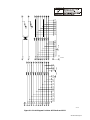
2-9. Selecting Weld Cable Sizes*
Weld Cable Size** and Total Cable (Copper) Length in Weld Circuit
Not Exceeding***
100 ft (30 m) or Less
150 ft
(45 m)
200 ft
(60 m)
250 ft
(70 m)
300 ft
(90 m)
350 ft
(105 m)
400 ft
(120 m)
Y Turn off power before
connecting to weld out-
put terminals.
Y Do not use worn, dam-
aged, undersized, or
poorly spliced cables.
Welding
Amperes
10 – 60%
Duty
Cycle
60 – 100%
Duty
Cycle
10 – 100% Duty Cycle
100 4 (20) 4 (20) 4 (20) 3 (30) 2 (35) 1 (50) 1/0 (60) 1/0 (60)
150 3 (30) 3 (30) 2 (35) 1 (50) 1/0 (60) 2/0 (70) 3/0 (95) 3/0 (95)
200 3 (30) 2 (35) 1 (50) 1/0 (60) 2/0 (70) 3/0 (95) 4/0 (120) 4/0 (120)
250 2 (35) 1 (50) 1/0 (60) 2/0 (70) 3/0 (95) 4/0 (120)
2 ea. 2/0
(2x70)
2 ea. 2/0
(2x70)
300 1 (50) 1/0 (60) 2/0 (70) 3/0 (95) 4/0 (120)
2 ea. 2/0
(2x70)
2 ea. 3/0
(2x95)
2 ea. 3/0
(2x95)
350 1/0 (60) 2/0 (70) 3/0 (95) 4/0 (120)
2 ea. 2/0
(2x70)
2 ea. 3/0
(2x95)
2 ea. 3/0
(2x95)
2 ea. 4/0
(2x120)
400 1/0 (60) 2/0 (70) 3/0 (95) 4/0 (120)
2 ea. 2/0
(2x70)
2 ea. 3/0
(2x95)
2 ea. 4/0
(2x120)
2 ea. 4/0
(2x120)
500 2/0 (70) 3/0 (95) 4/0 (120)
2 ea. 2/0
(2x70)
2 ea. 3/0
(2x95)
2 ea. 4/0
(2x120)
3 ea. 3/0
(3x95)
3 ea. 3/0
(3x95)
600 3/0 (95) 4/0 (120)
2 ea. 2/0
(2x70)
2 ea. 3/0
(2x95)
2 ea. 4/0
(2x120)
3 ea. 3/0
(3x95)
3 ea. 4/0
(3x120)
3 ea. 4/0
(3x120)
700 4/0 (120)
2 ea. 2/0
(2x70)
2 ea. 3/0
(2x95)
2 ea. 4/0
(2x120)
3 ea. 3/0
(3x95)
3 ea. 4/0
(3x120)
3 ea. 4/0
(3x120)
4 ea. 4/0
(4x120)
800 4/0 (120)
2 ea. 2/0
(2x70)
2 ea. 3/0
(2x95)
2 ea. 4/0
(2x120)
3 ea. 4/0
(3x120)
3 ea. 4/0
(3x120)
4 ea. 4/0
(4x120)
4 ea. 4/0
(4x120)
900
2 ea. 2/0
(2x70)
2 ea. 3/0
(2x95)
2 ea. 4/0
(2x120)
3 ea. 3/0
(3x95)
1000
2 ea. 2/0
(2x70)
2 ea. 3/0
(2x95)
2 ea. 4/0
(2x120)
3 ea. 3/0
(3x95)
1250
2 ea. 3/0
(2x95)
2 ea. 4/0
(2x120)
3 ea. 3/0
(3x95)
4 ea. 3/0
(4x95)
* This chart is a general guideline and may not suit all applications. If cable overheating occurs (normally you can smell it), use next size larger
cable.
**Weld cable size (AWG) is based on either a 4 volts or less drop or a current density of at least 300 circular mils per ampere.
( ) = mm
2
for metric use S-0007-E
***For distances longer than those shown in this guide, call a factory applications representative at 920-735-4505.

OM-210 540 Page 14
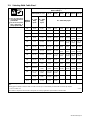
2-10. Peripheral Receptacle Functions
Function Socket Socket Information
K
M
J
L
H
E
F
Programmable
Output Relay Con-
A Contact closure to B dependent upon state of
programmed output.
A
B
M
C
L
D
E
Output Relay Con-
tacts
B Contact closure to A dependent upon state of
programmed output.
B
C
C* Circuit common.
Purge
D Contact closure to C completes 24 volts dc
solenoid circuit to purge shielding gas line.
Coolant Flow
Switch Input
Signal
E Contact closure to F indicates coolant flow switch is
closed and recirculating coolant system is
operational.
Signal
F* Circuit common.
Jog + H** Contact closure to circuit common advances
welding wire at wire drive assembly.
Jog – J** Contact closure to circuit common retracts welding
wire at wire drive assembly.
K Contact closure to L energizes Touch Sensor
circuitry.
Touch Sensor ON
And Output Signa
l
L* Circuit common.
Ref. 803 245-B
And Output Signal
M Part touched +24 volts dc output signal referenced
to circuit common.
*Circuit common is same electrical reference point.
**Speed of Jog + and Jog – is at setup value for Jog IPM parameter.
Note: A customer supplied matching amphenol plug (Part No. MS3106A20-33P and strain relief clamp AN3057-12) is required to use peripheral
receptacle.
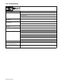
2-11. Electrical Service Guide
60 Hz
Input Voltage 230 460 575
Input Amperes At Rated Output 90 45 36
Max Recommended Standard Fuse Rating In Amperes
1
Time-Delay
2
110 50 40
Normal Operating 3 125 70 50
Min Input Conductor Size In AWG/Kcmil 3 8 8
Max Recommended Input Conductor Length In Feet (Meters)
173
(53)
231
(70)
361
(110)
Min Grounding Conductor Size In AWG/Kcmil 6 8 10
Reference: 1999 National Electrical Code (NEC)
1 Consult factory for circuit breaker applications.
2 “Time-Delay” fuses are UL class “RK5” .
3 “Normal Operating” (general purpose - no intentional delay) fuses are UL class “K5” (up to and including 60 amp), and UL class “H” ( 65 amp and
above).

OM-210 540 Page 15
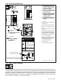
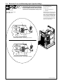
2-12. Connecting Input Power
801 535-B / 803 245-B / 802 777 / 213 848-A
Y Turn Off welding power source,
and check voltage on input ca-
pacitors according to Section
5-4 before proceeding.
Y Incorrect connections will
cause electric shock and dam-
age to the machine.
Y Have only qualified persons
perform these connections ac-
cording to all applicable codes
and safety practices.
Y Disconnect input power before
opening door for voltage con-
nections.
1 Clamp
Install clamp of proper size for unit and
input conductors.
2 Input And Grounding Conductors
Select size and length using Section
2-11.
Connect input conductors as shown in
illustration.
Connect grounding conductor first,
then line input conductors. Always
connect green wire to supply ground-
ing terminal, never to a line terminal.
Connect black, white, and red wires
(L1, L2, L3) to line terminals.
Double-check grounding conductor,
inside voltage connections, and input
voltage before applying power.
3 Line Disconnect Device
See Section 2-11.
Close door before operating unit.
Tools Needed:
5/16 in
= GND/PE
Y Always connect grounding
conductor first.
L1
3
L2
L3
1
2
Route ground conductor through
current transducer to ground terminal.
213 848–A
WARNING
ELECTRIC SHOCK can kill;
SIGNIFICANT DC VOLTAGE
exists after removal of
input power .
Always wait 60 seconds after power
is turned off before working on unit.
Check input capacitor voltage, and
be sure it is near 0 before touching
any parts.
Read Owner Manual.
L1
L2
L3
Three–Phase Input Connection
GND/PE GND/PE
Route input power cable
through tubing inside unit.
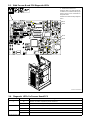
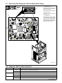
2-13. Touch Sensor Operation
The touch sensor feature allows the robot to locate a weldment using the wire feed system and welding power source.
The weld output terminals provide a path for touch sensor voltage when this feature is turned on at the peripheral
receptacle. Turning on touch sensor causes a dc voltage to be present on the welding wire. When welding wire
touches the weldment, the voltage sensing circuit closes, and a +24 volts dc output signal is sent to the robot control
indicating weldment detection. Touch sensor dc voltage on the welding wire is 80 volts DC. As soon as touch sensor
turns on, WIRE LIVE appears on the front panel display.

OM-210 540 Page 16
SECTION 3 – OPERATION
3-1. Operational Terms
The following is a list of terms and their definitions as they apply to this interface unit:
General Terms:
Adaptive Pulse Welding When the “adaptive pulse” welding process is selected, the unit will attempt to automatically regulate
pulse frequency in order to maintain a constant arc length, regardless of change in welding wire stick-
out.
Abk (Background Amperage) Abk is the low weld current. Background current preheats welding wire and maintains the arc. When
background current is too low, the arc is unstable and hard to maintain.
Apk (Peak Amperage) Apk is the high pulse of welding current. Peak current melts the welding wire and forms a droplet. The
droplet is forced into the weld puddle.
Vpk (Peak Voltage) Arc voltage during peak current phase of the pulse waveform. This determines arc length during
adaptive pulse welding.
Inductance In short circuit GMAW welding, an increase in inductance will decrease the number of short circuit
metal transfers per second (provided no other changes are made) and increase the arc-on time. The
increased arc-on time makes the pool more fluid.
PPS (Pulses Per Second) PPS, pulse rate, and frequency (Hz) are used interchangeably. A PPS or pulse rate of 60 Hz means
60 pulses of current are produced each second.
PWms (Pulse Width in Milliseconds) PWms is the time spent at peak current (1.2 ms is .0012 seconds). This time must be long enough to
form a droplet of welding wire. The stiffness or fluidity of the molten weld puddle is controlled by
PWms.
Synergic Synergic refers to the unit’s ability to use preprogrammed pulse parameters to determine the actual
pulse settings of Peak Amperage, Background Amperage, Pulse Frequency and Pulse Width at any
specific wire feed speed setting.
Trim Term used to represent arc length adjustments in pulse programs. Increasing trim increases the ac-
tual arc length. Likewise, decreasing trim shortens arc length. Trim is replaced by volts in MIG pro-
grams.
La page est en cours de chargement...
La page est en cours de chargement...
La page est en cours de chargement...
La page est en cours de chargement...
La page est en cours de chargement...
La page est en cours de chargement...
La page est en cours de chargement...
La page est en cours de chargement...
La page est en cours de chargement...
La page est en cours de chargement...
La page est en cours de chargement...
La page est en cours de chargement...
La page est en cours de chargement...
La page est en cours de chargement...
La page est en cours de chargement...
La page est en cours de chargement...
La page est en cours de chargement...
La page est en cours de chargement...
La page est en cours de chargement...
La page est en cours de chargement...
La page est en cours de chargement...
La page est en cours de chargement...
La page est en cours de chargement...
La page est en cours de chargement...
La page est en cours de chargement...
La page est en cours de chargement...
La page est en cours de chargement...
La page est en cours de chargement...
La page est en cours de chargement...
La page est en cours de chargement...
La page est en cours de chargement...
La page est en cours de chargement...
La page est en cours de chargement...
La page est en cours de chargement...
La page est en cours de chargement...
La page est en cours de chargement...
La page est en cours de chargement...
La page est en cours de chargement...
La page est en cours de chargement...
La page est en cours de chargement...
La page est en cours de chargement...
La page est en cours de chargement...
La page est en cours de chargement...
La page est en cours de chargement...
La page est en cours de chargement...
La page est en cours de chargement...
La page est en cours de chargement...
La page est en cours de chargement...
La page est en cours de chargement...
La page est en cours de chargement...
La page est en cours de chargement...
La page est en cours de chargement...
-
 1
1
-
 2
2
-
 3
3
-
 4
4
-
 5
5
-
 6
6
-
 7
7
-
 8
8
-
 9
9
-
 10
10
-
 11
11
-
 12
12
-
 13
13
-
 14
14
-
 15
15
-
 16
16
-
 17
17
-
 18
18
-
 19
19
-
 20
20
-
 21
21
-
 22
22
-
 23
23
-
 24
24
-
 25
25
-
 26
26
-
 27
27
-
 28
28
-
 29
29
-
 30
30
-
 31
31
-
 32
32
-
 33
33
-
 34
34
-
 35
35
-
 36
36
-
 37
37
-
 38
38
-
 39
39
-
 40
40
-
 41
41
-
 42
42
-
 43
43
-
 44
44
-
 45
45
-
 46
46
-
 47
47
-
 48
48
-
 49
49
-
 50
50
-
 51
51
-
 52
52
-
 53
53
-
 54
54
-
 55
55
-
 56
56
-
 57
57
-
 58
58
-
 59
59
-
 60
60
-
 61
61
-
 62
62
-
 63
63
-
 64
64
-
 65
65
-
 66
66
-
 67
67
-
 68
68
-
 69
69
-
 70
70
-
 71
71
-
 72
72


Miller Auto-Axcess 450 Le manuel du propriétaire
- Catégorie
- Système de soudage
- Taper
- Le manuel du propriétaire
- Ce manuel convient également à
dans d''autres langues
Documents connexes
-
Miller Auto-Axcess 450 Le manuel du propriétaire
-
-
-
-
-
-
-
-
-