Tetra 24V GEPS24D-80U Signage Power Supply Guide d'installation
- Taper
- Guide d'installation

Installation Guide
SIGN200 | GE2022-3612
Power Supply Features
• Supports all 24 VDC Tetra Products
• Dry and Damp Locations Rated
• Class 2 Power Supply
• 100-277 VAC Input
• Compatible with 0-10V Dimming controller
WARNING / AVERTISSEMENT
RISK OF ELECTRIC SHOCK
• Disconnect power at fuse box or circuit breaker before servicing or
installing product.
• Properly ground Tetra® power supply.
• Must be enclosed in an end product.
RISK OF FIRE
• In the end product, power supply spacing to other heat producing
components shall be minimum 2 inches spacing to sidewalls and
minimum 2 inches spacing to top of enclosure.
• Adjacent power supplies shall be spaced at least 1 in. end to end
and 4 in. in any other direction.
• Use only approved wire for input/output connection. Minimum
size 18 AWG (0.82 mm2).
• Follow all local codes.
• Application considerations potentially requiring additional spacing
include high ambient temperature seen by the power supply, poor
contact with a heat dissipating material, inadequate ventilation, or
direct exposure to sun.
RISQUES DE DÉCHARGES ÉLECTRIQUES
• Coupez l’alimentation électrique à la boîte de fusibles ou au disjoncteur avant
l’entretien ou l’installation du produit.
• Assurez-vous de correctement mettre à terre le bloc d’alimentation Tetra®.
• Doit être inclus à l’intérieur d’un produit final.
RISQUES D’INCENDIE
• Dans le produit fini, l’espacement entre le bloc d’alimentation et les autres
composants dégageant de la chaleur doit être d’au moins 2 pouces des
parois latérales et d’au moins 2 pouces du haut de l’enceinte.
• Les blocs d’alimentation adjacents doivent être espacés d’au moins 1 po de
bout en bout et 4 po dans toute autre direction.
• N’utilisez que des fils approuvés pour les entrées/sorties de connexion.
Taille minimum 18 AWG (0.82 mm2).
• Respectez tous les codes locaux.
• Certaines applications pourraient requérir un espacement additionnel, p.
ex. une température ambiante élevée autour du bloc d’alimentation, un
mauvais contact avec une matière dissipatrice de chaleur, une ventilation
inadéquate ou une exposition directe au soleil.
Save These Instructions
Use only in the manner intended by the manufacturer.
If you have any questions, contact the manufacturer.
Prepare Electrical Wiring
Electrical Requirements
• Limited to use in dry and damp locations.
• The suitability of rain enclosure shall be determined if
intended for wet location.
• The grounding and bonding of the LED Driver shall be
done in accordance with National Electric Code (NEC)
Article 600.
• Follow all National Electric Codes (NEC) and local codes.
LED Systems Power Supply
GEPS24D-80U (100-277 VAC input/24VDC output/80W/0-10V Dimming)
2424
Volt
BEFORE YOU BEGIN
Read these instructions completely and carefully.
CAUTION / ATTENTION
RISK INJURY
• While performing installations described, gloves, safety
glasses or goggles should be worn.
RISQUES DE BLESSURE
• Lors de l’exécution des installations décrites, des gants, des lunettes
de sécurité ou des lunettes de protection doivent être portées.

Tetra® Power Supply GEPS24D-80U Installation Guide
2
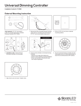
Power Supply Installation
Mount the power supply with the
base in contact with the mounting
surface in an electrical enclosure
with adequate dimensions to
satisfy the power supply spacing
requirements described above,
and suitable for the installation
environment. The power supply
and electrical connections shall be
protected from weather and not
subject to saturation with water
or other liquids. If not protected
from the weather, the output and
dimming connections may be
sealed with electrical grade silicone.
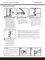
Connect the supply wire that
is attached to the Tetra LED
System to the red (+) and
black (-) output wires of the
power supply as outlined in the
“Electrical Connections” section
of your LED system’s Installation
Instructions.
Connect the AC line to the black
(line) and white (neutral) input
wires of the power supply using
18-14 AWG (0.82-2.08 mm2)
or 18-10 AWG (0.82-5.26mm2)
twist-on wire connectors.
Properly ground power supply in
accordance with National Electric
Code (NEC) Article 600.
Connect the (+) purple and (-) gray
wires of the Tetra Dimming Power
Supply to the 0-10V dimming
controller. Refer to the dimming
controller installation instructions
for specific connection information.
NOTE: To avoid overloading this
power supply with LED modules,
please refer to the specific module
loading guides.
To Tetra LED System
To Dimming
controller
Output
wires
White (neutral)
Black (line)
Red (+) Black (-)
AC line
To Tetra LED System
Purple (+)
Purple (+)
Gray (-)
Gray (-)
Dimming
controller
NOTE: For CSA approval, a disconnect/toggle switch of appropriate rating
needs to be placed within 29.5 ft. (9 m) of primary side of the power
supply. The minimum rating of the switch must be either 120 or 220 Volts
AC. The switch must also support twice the amount of input current.
NOTE: When installing power supply, connect to the appropriate sized
building breaker or disconnect device for line and neutral connections, in
accordance with local, state or country regulations.
NOTE: The grounding and bonding of the power supply and overall sign
shall be done in accordance with National Electric Code (NEC) Article 600.
1
4
OPTIONAL
A Weather Box (GEXNWB2) may be used to
house and seal Class 2 connections.
A) Insert wire connectors into weather box. Fill
with electrical grade silicone and close box.
B) Secure the weather box using a #6 or #8
(M2 or M3) screw.
Weather box
can be painted
Light engine
A B
2 3

Tetra® Power Supply GEPS24D-80U Installation Guide
LED.com
© 2023 Current Lighting Solutions, LLC. All rights reserved. Information and specifications subject to change
without notice. All values are design or typical values when measured under laboratory conditions.
Page 3 of 3
(Rev 06/19/23)
SIGN200 | GE2022-3612
Power Supply Specifications
Performance Data Min Typical Max
Input Voltage (VAC) 90 100-277 305
Input Frequency (Hz) – 50/60 –
Input Current (A) – – 1.1
THD – – 20
PF 0.9 – –
Output Voltage (VDC) 23.0 – 25.5
Output Current (ADC) – – 3.3
Output Power (W) – – 80
Environmental Operating Temperature Range -40°C +25°C +60°C*
Environmental Humidity (non-condensing) 10% – 90%
Environmental Storage Temperature Range -40°C – +85°C
Environmental Rating IP66 rated: must be protected from direct exposure to the weather
Dimensions 9.5 in. x 1.7 in. x 1.2 in. (240 mm x 43 mm x 30 mm)
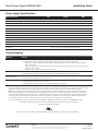
Conforms to the following standards:
This product is intended to be used as a lamp control gear that is installed after the mains control switch.
For the most up-to-date version of this installation guide, please visit https://products.LED.com/sign-lighting
*Maximum case temperature is 85°C
Symptom Solution
All letters are OFF • Recycle AC power, turn it off, then turn on again.
• If still off, check the power supply DC output voltage using a voltmeter. It should be nominally 24V.
»If there is DC output, inspect and correct all DC wire damage/polarity issues; If no issue is found, replace the
OFF-module string.
»If there is no DC output, have a licensed electrician check the input AC voltage and if there is correct AC voltage,
replace the power supply.
»If there is no AC voltage, correct the upstream AC issue.
Some LEDs appear dim • Ensure the overall length of the Tetra® LED System does not exceed the maximum load.
• Ensure the length of supply wire is equal to or below the recommended remote mounting distance.
Some of the letters
are not illuminated
• Inspect and correct the wires of the non-illuminated letters for damage/polarity issues; If no issues are found, see the
troubleshooting solution for “All letters are OFF.”
Shadows • Re-route supply wire and secure to the back of the can with electrical grade RTV silicone. Adjust wire connector
orientation so that it does not cover any LEDs.
• Adjust LED layout to ensure uniformity of illumination of the face of the letter.
Troubleshooting
This device complies with part 15 of the FCC Rules. Operation is subject to the following two conditions: (1) This device may not cause harmful
interference, and (2) this device must accept any interference received, including interference that may cause undesired operation.
Note: This equipment has been tested and found to comply with the limits for a Class A digital device, pursuant to part 15 of the FCC Rules.
These limits are designed to provide reasonable protection against harmful interference when the equipment is operated in a commercial
environment. This equipment generates, uses, and can radiate radio frequency energy and, if not installed and used in accordance with the
instruction manual, may cause harmful interference to radio communications. Operation of this equipment in a residential area is likely to
cause harmful interference in which case the user will be required to correct the interference at his own expense.
This Class [A] RFLD complies with the Canadian standard ICES-005. Ce DEFR de la classe [A] est conforme à la NMB-005 du Canada.
-
 1
1
-
 2
2
-
 3
3


Tetra 24V GEPS24D-80U Signage Power Supply Guide d'installation
- Taper
- Guide d'installation
dans d''autres langues
Documents connexes
-
Tetra 12V GEPS12D-60U Signage Power Supply Guide d'installation
-
-
-
-
-
-
-
-
-