Dometic Horizon 3310602.000_3310897.000_Motor Conversion Guide d'installation
- Taper
- Guide d'installation

USA
SERVICE OFFICE
Dometic Corporation
2320 Industrial Parkway
Elkhart, IN 46516
574-294-2511
CANADA
Dometic Corporation
46 Zatonski, Unit 3
Brantford, ON N3T 5L8
CANADA
519-720-9578
For Service Center
Assistance Call:
MOTOR CONVERSION
INSTALLATION INSTRUCTIONS
MODELS
3310602.000(#)
3310897.000(#)
When ordering parts, always state:
MODEL NO. - PRODUCT NO. - QUANTITY -
PART NUMBER - DESCRIPTION
For Electric Details also state:
VOLTAGE - WATTAGE
Form No. 3310831.000 9/07
(French 3310900.000)
©2007 Dometic Corporation
LaGrange, IN 46761
This manual must be read and understood
before installation, adjustment, service, or
maintenance is performed. This unit must
be installed by a qualied service techni-
cian. Modication of this product can be
extremely hazardous and could result in
personal injury or property damage.
Lire et comprendre ce manuel avant de
procéder à l’installation, à des réglag-
es, de l’entretien ou des réparations.
L’installation de cet appareil doit être ef-
fectuée par un réparateur qualié. Toute
modication de cet appareil peut être ex-
trêmement dangereuse et entraîner des
blessures ou dommages matériels.
®

2
HORIZON 979(XX)(XX).065 MOTOR CONVERSION KIT
Safety Instructions
This manual has safety information and instructions
to help users eliminate or reduce the risk of acci-
dents and injuries.
Recognize Safety Information
This is the safety-alert symbol. When you see this
symbol in this manual, be alert to the potential for
personal injury.
Follow recommended precautions and safe operat-
ing instructions.
Understand Signal Words
A signal word , WARNING OR CAUTION is used
with the safety-alert symbol. They give the level of
risk for potential injury.
indicates potentially hazardous
situation which, if not avoided, could result in death
or serious injury.
indicates a potentially hazardous
situation which, if not avoided, may result in minor
or moderate injury.
used without the safety alert
symbol indicates, a potentially hazardous situation
which, if not avoided, may result in property dam-
age.
Read and follow all safety information and instruc-
tions.
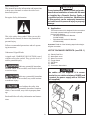
Fig. 1
A. Application
The Horizon motor kit is designed for the conversion
of manual operated awnings to electric operated
Horizon Case Awning.
Left Hand Conversion Kit Number
3310897.000(#)
Right Hand Conversion Kit Number
3310602.000(#)
Important: Read all of the following steps before begin-
ning the conversion.
LIST OF PACKAGE CONTENTS: (see FIG. 1)
(4) - Plastic Push Pins
(1) - Motor Back cover
(1) - Motor Front cover
(1) - Toggle Switch
(1) - Pop Rivet
(1) - Motor
(1) - Conversion Instructions
The cables are not supplied. It is recom-
mended to use cables minimum 18AWG and
to protect the power supply with a 16A fuse
(not supplied).
•
•
These instructions must be read and under-
stood before installation of motor kit. Kit must
be installed by a Dometic Service Center or
a qualied service technician. Modication
of this product can be extremely hazardous
and could result in personal injury or property
damage.

3
HORIZON 979(XX)(XX).065 MOTOR CONVERSION KIT
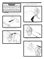
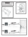
B. Installation
1. Extend awning to the open position. See FIG 2.
Fig. 2
2. Remove drive side cover. See FIG. 3
3. Drill out fastener as shown in FIG. 4.
Fig. 4
Fig. 3
Fig. 6
4. Remove screws as shown in FIG. 5.
Fig. 5
5. Remove manual drive assembly as shown in
FIG. 6.
There may be electrical wiring, pipes or oth-
er items in the walls. Disconnect 115 volt AC
power cord and the positive (+) 12 volt DC
terminal at the supply battery. Failure to fol-
low this instruction may create a shock haz-
ard causing death or severe personal injury.

4
HORIZON 979(XX)(XX).065 MOTOR CONVERSION KIT
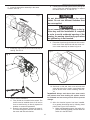
5. Insert the motor drive assembly in the same
location. See FIG. 7.
Fig. 7
6. Insert pop rivet to secure new motor assembly to
awning. See FIG. 8.
Fig. 8
7. Remote Switch Installation
a. First, decide on a location for the switch. The
switch must be installed where it will not be
close to steel framing or directly exposed to
weather or extreme temperatures.
b. Route the wire harness. Choose the most di-
rect route through the wall from the switch to
the motor and limit switch wires.
Do not disconnect or change the micro
switch. Do not use different switches than
the one supplied.
Do not connect the power supply to the ig-
nition key until the installation is complete
in order to avoid accidental opening of the
awning; the awning should only open when
the ignition key is not inserted.
9. Route the wires through the hole slot in the motor
back cover. Place both front and rear motor cov-
ers to motor assembly as shown in gure 9.
Fig. 9
10. Seal hole in side wall, back cover wire slot and
wires with clear silicon sealer. Insert plastic push
pins to secure motor covers to awning. See FIG.
10.
Important: Always seal where wires enter coach
and protect wires from chang. All splices should
be insulated and secure any excess wire to prevent
damage.
11. After the electrical system has been installed,
do a general functioning test by following these
points. See Figure 12 for reference.
a. Make sure the awning opens, the switch is in
position EXTEND and that it closes when the
switch is in the RETRACT.
8. Connect the electrical system before placing the
cover. Follow the electrical diagram to connect
the cables. See FIG. 11 and FIG. 13.

5
HORIZON 979(XX)(XX).065 MOTOR CONVERSION KIT
Fig. 10
Fig. 11
When the awning is moving, never touch the
mechanical parts of the awning and in par-
ticular the lead bar and the awning case.
MICRO-SWITCH
BLACK
GREY
Fig. 12

6
HORIZON 979(XX)(XX).065 MOTOR CONVERSION KIT
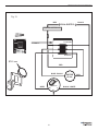
RETRACT
EXTEND
Ø 45 mm
Fig. 13
GREY
RED
MOTOR
12 Vdc
RED
BLUE - BLACK
BLACK - WHITE
IGNITION INTERLOCK
Nc
MICRO-SWITCH
No
C
+
RED 12Vdc SUPPLY _BLACK
-
 1
1
-
 2
2
-
 3
3
-
 4
4
-
 5
5
-
 6
6


Dometic Horizon 3310602.000_3310897.000_Motor Conversion Guide d'installation
- Taper
- Guide d'installation
dans d''autres langues
Documents connexes
-
Dometic Milenco Locking Hitch Pin DM-4985 Guide d'installation
-
-
-
-
-
-
-
-
-