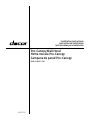
Dacor DHD48U990CS Guide d'installation
- Catégorie
- Hottes
- Taper
- Guide d'installation
Ce manuel convient également à

LIB0179901
Installation Instructions
Instructions d’Installation
Instrucciones para instalación
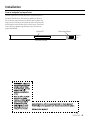
Pro-Canopy Wall Hood
Hotte murale Pro-Canopy
Campana de pared Pro-Canopy
DHD**U990C*/DA

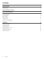
ENGLISH2
Contents
Before You Begin 3
Important Notes 3
Customer Service 3
Important Safety Instructions 4
Installation Requirements 7
Electrical requirements 7
Venting requirements 8
Venting methods 8
Ducting options 9
What is in the box 10
Tools and parts 10
Dimentions and clearances 11
Accessories - Sold Separately 11
Installation 12
Installation instructions 12
Outside top exhaust 12
Complete preparation 15
Mounting the hood 16
Install hood internal fan motor 16
Electrical connection 18
Completing the installation 19
Attach Dacor badge 20

ENGLISH 3
Important Notes
Installer
• In the interest of safety and to minimize problems, read this manual thoroughly before starting the installation.
• Leave this manual with the customer.
• Show the owner how to shut off power to the hood.
Customer
Keep this manual for personal and professional reference.
Customer Service
To resolve questions and installation issues, contact your Dacor dealer or Dacor customer service. Before calling, have
the hood’s model and serial number available. (See the data label inside the hood above the lters on the chassis’ rear
wall).
All specications are subject to change without notice. Dacor assumes no liability for such changes.
©2022 Dacor, all rights reserved.
Before You Begin

ENGLISH4
APPROVED FOR RESIDENTIAL APPLIANCES
FOR RESIDENTIAL USE ONLY
READ AND SAVE THESE INSTRUCTIONS
PLEASE READ ENTIRE INSTALLATION GUIDE BEFORE PROCEEDING.
INSTALLATION MUST COMPLY WITH ALL LOCAL CODES.
IMPORTANT: Save these instructions for the local electrical inspector’s use.
INSTALLER: Please leave these instructions with this unit for the owner.
OWNER: Please retain these instructions for future reference.
Symbols used in this manual
WARNING
Hazards or unsafe practices that may result in severe personal injury or death.
WARNING
Turn off power circuit at service panel and lock out panel before wiring this appliance.
CAUTION
Hazards or unsafe practices that may result in electric shock, personal injury, or property damage.
NOTE
Useful tips and instructions.
These warning icons and symbols are here to prevent injury to you and others.
Please follow them explicitly. After reading this section, keep it in a safe place for future reference.
State of California Proposition 65 warning (US only)
WARNING
This product contains chemicals known to the State of California to cause cancer and birth defects or other
reproductive harm - www.p65warnings.ca.gov
1. FCC Notice
CAUTION
FCC CAUTION:
Any changes or modi cations not expressly approved by the party responsible for compliance could void the user’s
authority to operate the equipment.
This device complies with Part 15 of FCC Rules. Operation is subject to following two conditions:
1. This device may not cause harmful interference, and
2. This device must accept any interference received including interference that cause undesired operation.
For products sold in the US and Canadian markets, only channels 1~11 are available. You cannot select any other
channels.
FCC STATEMENT:
This equipment has been tested and found to comply within the limits for a Class B digital device, pursuant to part 15 of
the FCC Rules. These limits are designed to provide reasonable protection against harmful interference in a residential
installation.
Important Safety Instructions

ENGLISH 5
APPROVED FOR RESIDENTIAL APPLIANCES
FOR RESIDENTIAL USE ONLY
READ AND SAVE THESE INSTRUCTIONS
PLEASE READ ENTIRE INSTALLATION GUIDE BEFORE PROCEEDING.
INSTALLATION MUST COMPLY WITH ALL LOCAL CODES.
IMPORTANT: Save these instructions for the local electrical inspector’s use.
INSTALLER: Please leave these instructions with this unit for the owner.
OWNER: Please retain these instructions for future reference.
Symbols used in this manual
WARNING
Hazards or unsafe practices that may result in severe personal injury or death.
WARNING
Turn off power circuit at service panel and lock out panel before wiring this appliance.
CAUTION
Hazards or unsafe practices that may result in electric shock, personal injury, or property damage.
NOTE
Useful tips and instructions.
These warning icons and symbols are here to prevent injury to you and others.
Please follow them explicitly. After reading this section, keep it in a safe place for future reference.
State of California Proposition 65 warning (US only)
WARNING
This product contains chemicals known to the State of California to cause cancer and birth defects or other
reproductive harm - www.p65warnings.ca.gov
1. FCC Notice
CAUTION
FCC CAUTION:
Any changes or modi cations not expressly approved by the party responsible for compliance could void the user’s
authority to operate the equipment.
This device complies with Part 15 of FCC Rules. Operation is subject to following two conditions:
1. This device may not cause harmful interference, and
2. This device must accept any interference received including interference that cause undesired operation.
For products sold in the US and Canadian markets, only channels 1~11 are available. You cannot select any other
channels.
FCC STATEMENT:
This equipment has been tested and found to comply within the limits for a Class B digital device, pursuant to part 15 of
the FCC Rules. These limits are designed to provide reasonable protection against harmful interference in a residential
installation.
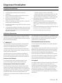
Important Safety Instructions
This equipment generates, uses, and can radiate radio frequency energy and, if not installed and used in accordance
with the instructions, may cause harmful interference to radio communications.
However, there is no guarantee that interference will not occur in a particular installation. If this equipment does cause
harmful interference to radio or television reception, which can be determined by turning the equipment off and on,
the user is encouraged to try to correct the interference by one or more of the following measures:
• Reorienting or relocating the receiving antenna
• Increasing the separation between the equipment and receiver
• Connecting the equipment to an outlet that is on a different circuit than the radio or TV
• Consulting the dealer or an experienced radio/TV technician for help
FCC RADIATION EXPOSURE STATEMENT:
This equipment complies with FCC radiation exposure limits set forth for an uncontrolled environment. This equipment
should be installed and operated so there is at least 8 inches (20 cm) between the radiator and your body. This device
and its antenna(s) must not be co-located or operated in conjunction with any other antenna or transmitter.
2. IC Notice
The term “IC” before the radio certi cation number only signi es that Industry Canada technical speci cations were
met. Operation is subject to the following two conditions: (1) this device may not cause interference, and (2) this device
must accept any interference, including interference that may cause undesired operation of the device.
This Class B digital apparatus complies with Canadian ICES-003. For products sold in the US and Canadian markets,
only channels 1~11 are available. You cannot select any other channels.
IC RADIATION EXPOSURE STATEMENT:
This equipment complies with IC RSS-102 radiation exposure limits set forth for an uncontrolled environment. This
equipment should be installed and operated so there is at least 8 inches (20 cm) between the radiator and your body.
This device and its antenna(s) must not be co-located or operated in conjunction with any other antenna or transmitter.
WARNING
TO REDUCE THE RISK OF FIRE, ELECTRIC SHOCK, OR INJURY TO PERSONS, OBSERVE THE FOLLOWING PRECAUTIONS:
• Use this unit only in the manner intended by the manufacturer. If you have questions, contact the manufacturer.
• Before servicing or cleaning the unit, switch the power off at the service panel and lock the service panel to
prevent power from being switched on accidentally. If the service panel cannot be locked, securely fasten a
prominent warning device, such as a tag to the service panel.
• Installation work and electrical wiring must be done by quali ed person(s) in accordance with all applicable codes
and standards, including re-rated construction.
• Suf cient air is needed for proper combustion and exhausting of gases through the ue (chimney) of fuel burning
equipment to prevent backdrafting. Follow the heating equipment manufacturer’s guideline and safety standards
such as those published by the National Fire Protection Association (NFPA), the American Society for Heating,
Refrigeration and Air Conditioning Engineers (ASHRAE), and the local code authorities.
• When cutting or drilling into the wall or ceiling; do not damage electrical wiring and other hidden utilities.
• Ducted fans must always be vented outdoors.
CAUTION
For general ventilating use only. Do not use to exhaust hazardous or explosive materials and vapors.

ENGLISH6
Important Safety Instructions
CAUTION
To reduce risk of re and to properly exhaust air, be sure to duct air outside - do not vent exhaust air into spaces within
walls or ceilings, attics or into crawl spaces, or garages.
WARNING
TO REDUCE THE RISK OF FIRE, USE ONLY METAL DUCTWORK
WARNING
TO REDUCE THE RISK OF A RANGE TOP GREASE FIRE:
• Never leave surface units unattended at high settings. Boilovers cause smoking and greasy spillovers that may
ignite. Heat oils slowly on low or medium settings.
• Always turn the hood ON when cooking at high heat or when ambeing food (i.e. Crepes Suzette, Cherries Jubilee,
Peppercorn Beef Flambé).
• Clean ventilating fans frequently. Grease should not be allowed to accumulate on the fan or lter.
• Use proper pan sizes. Always use cookware appropriate for the size of the surface element.
WARNING
TO REDUCE THE RISK OF INJURY TO PERSONS IN THE EVENT OF A RANGE TOP GREASE FIRE, OBSERVE THE
FOLLOWING PRECAUTIONS:*
• SMOTHER FLAMES with a close tting lid, cookie sheet, or metal tray, then turn off the burner.
BE CAREFUL TO PREVENT BURNS. If the ames do not go out immediately, EVACUATE AND CALL THE FIRE
DEPARTMENT.
• NEVER PICK UP A FLAMMING PAN - you may get burned.
• DO NOT USE WATER, including wet dishcloths or towels - a violent steam explosion will result.
• Use an extinguisher ONLY if:
- You know you have a class ABC extinguisher, and you already know how to operate it.
- The re is small and contained in the area where it started.
- The re department is being called.
- You can ght the re with your back to an exit.
*Based on “Kitchen Fire Safety Tips” published by NFPA.
WARNING
To reduce the risk of re or electrical shock, do not use this fan with any solid-state speed control device.
WARNING
Do not let children near this appliance. Do not let children play with this appliance.
Keep all packaging materials out of children’s reach. Properly dispose the packaging materials after this appliance is
unpacked.
NOTE
Suitable for use in household cooking area.
Read and save these Instructions

ENGLISH 7
Installation Requirements
Electrical requirements
IMPORTANT
Observe all governing codes and ordinances.
It is the customer’s responsibility:
• To contact a qualied electrical installer.
• To assure that the electrical installation is adequate
and in conformance with National Electrical Code,
ANSI/NFPA 70 — latest edition*, or CSA Standards
C22.1-94, Canadian Electrical Code, Part 1 and C22.2
No.0-M91 - latest edition** and all local codes and
ordinances.
If codes permit and a separate ground wire is used, it is
recommended that a qualied electrician determine that
the ground path is adequate.
A copy of the above code standards can be obtained from:
National Fire Protection Association
1 Batterymarch Park
Quincy, MA 02169-7471
CSA International
8501 East Pleasant Valley Road
Cleveland, OH 44131-5575
• A 120 volt, 60 Hz., AC only, 15-amp, fused electrical
circuit is required.
• If the house has aluminum wiring, follow the
procedure below.
1. Connect a section of solid copper wire to the pigtail
leads.
2. Connect the aluminum wiring to the added section
of copper wire using special connectors and/or
tools designed and UL listed for joining copper to
aluminum.
• Follow the electrical connector manufacturer’s
recommended procedure. Aluminum/copper
connection must conform with local codes and
industry accepted wiring practices.
• Wire sizes and connections must conform with the
rating of the appliance as specied on the model/
serial rating plate. The model/serial plate is located
behind the lter on the rear wall of the hood.
• Wire sizes must conform to the requirements of
the National Electrical Code, ANSI/NFPA 70 (latest
edition), or CSA Standards C22. 1-94, Canadian
Electrical Code, Part 1 and C22.2 No. 0-M91 (latest
edition and all local codes and ordinances).
Important Safety Instructions
CAUTION
To reduce risk of re and to properly exhaust air, be sure to duct air outside - do not vent exhaust air into spaces within
walls or ceilings, attics or into crawl spaces, or garages.
WARNING
TO REDUCE THE RISK OF FIRE, USE ONLY METAL DUCTWORK
WARNING
TO REDUCE THE RISK OF A RANGE TOP GREASE FIRE:
• Never leave surface units unattended at high settings. Boilovers cause smoking and greasy spillovers that may
ignite. Heat oils slowly on low or medium settings.
• Always turn the hood ON when cooking at high heat or when ambeing food (i.e. Crepes Suzette, Cherries Jubilee,
Peppercorn Beef Flambé).
• Clean ventilating fans frequently. Grease should not be allowed to accumulate on the fan or lter.
• Use proper pan sizes. Always use cookware appropriate for the size of the surface element.
WARNING
TO REDUCE THE RISK OF INJURY TO PERSONS IN THE EVENT OF A RANGE TOP GREASE FIRE, OBSERVE THE
FOLLOWING PRECAUTIONS:*
• SMOTHER FLAMES with a close tting lid, cookie sheet, or metal tray, then turn off the burner.
BE CAREFUL TO PREVENT BURNS. If the ames do not go out immediately, EVACUATE AND CALL THE FIRE
DEPARTMENT.
• NEVER PICK UP A FLAMMING PAN - you may get burned.
• DO NOT USE WATER, including wet dishcloths or towels - a violent steam explosion will result.
• Use an extinguisher ONLY if:
- You know you have a class ABC extinguisher, and you already know how to operate it.
- The re is small and contained in the area where it started.
- The re department is being called.
- You can ght the re with your back to an exit.
*Based on “Kitchen Fire Safety Tips” published by NFPA.
WARNING
To reduce the risk of re or electrical shock, do not use this fan with any solid-state speed control device.
WARNING
Do not let children near this appliance. Do not let children play with this appliance.
Keep all packaging materials out of children’s reach. Properly dispose the packaging materials after this appliance is
unpacked.
NOTE
Suitable for use in household cooking area.
Read and save these Instructions

ENGLISH8
Installation Requirements
Venting requirements
• Vent system must terminate outdoors.
• Do not terminate the vent system in an attic or other
enclosed area.
• Do not use a 4” (10.2 cm) laundry-type wall cap.
• Use metal vent only. Rigid metal vent is
recommended.
• Plastic or metal foil vent is not recommended.
• The length of the vent system and the number of
elbows should be kept to a minimum to provide
efcient performance. For the most efcient and
quiet operation:
- Use no more than three 90° elbows.
- Make sure there is a minimum of 30” (76.2 cm)
of straight vent between the elbows if more than 1
elbow is used. Do not install 2 elbows together.
• Use clamps to seal all joints in the vent system.
• The vent system must have a damper. If the roof
or wall cap has a damper, do not use the damper
supplied with the hood.
• Use caulking to seal the exterior wall or roof opening
around the cap.
• The size of the vent should be uniform.
Venting methods
To use the hood’s top outlet to vent your hood, a 10” (25.4
cm) round vent system is required. This vent system is not
included and must be purchased separately.
NOTE
Flexible vent is not recommended. Flexible vent creates
back pressure and air turbulence that greatly reduces
performance. The vent system can terminate either
through the roof or wall.
Always install a metal vent cover where the ductwork
exits the house. Hood must be vented to the outside of
building only.
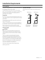
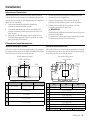
Discharge direction
This hood is factory set for venting through the roof
(vertical discharge) or wall (horizontal discharge).
To vent through a wall, a 90° elbow is needed.
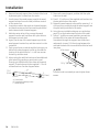
Ductwork installation guidelines
For safety reasons, ducting should vent directly outdoors
(not into an attic, underneath the house, into the garage
or into any enclosed space). Do not exceed 50 ft (15.24 m)
of duct. Keep duct runs as short and straight as possible.
Elbows and transition ttings reduce air ow efciency.
Back to back elbows and “S” turns give very poor delivery
and are not recommended. A short straight length of duct
at the inlet of a remote fan gives the best delivery.
Ducting recommendations
Proper performance is dependent upon proper ducting.
Cold weather
Cold weather installations should have an additional
backdraft damper installed to minimize backward cold
air ow and a nonmetallic thermal break to minimize
conduction of outside temperatures as part of the
ductwork. The damper should be on the cold air side
of the thermal break. The break should be as close as
possible to where the ducting enters the heated portion
of the house.
Make-up air
Local building codes may require the use of make-up air
systems when using ducted ventilation systems greater
than specied CFM of air movement. The specied CFM
varies from locale to locale. It is the responsibility of
the owner and the installer to determine if additional
requirements and/or standards apply to specic
installations.

ENGLISH 9
Installation Requirements
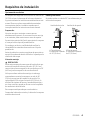
Ducting options
The hood is equipped with a 10” (25.4 cm) round transition
for discharge of fumes to the outside.
Closely follow the instructions set out in this manual.
Dacor is not responsible for any eventual inconveniences,
damages or res caused by not complying with the
instructions in this manual.
Preparation
Do not cut a joist or stud unless absolutely necessary. If a
joist or stud must be cut, then a supporting frame must be
constructed.
Fittings material is provided to secure the hood to most
types of walls/ceilings.
However, a qualied technician must verify suitability of
the materials in accordance with the type of wall/ceiling.
Before making cutouts, make sure there is proper
clearance within the ceiling or wall for the exhaust vent.
Mounting height
CAUTION
Mount this hood so that the bottom edge above the
cooking surface is at 30”(76.2cm) minimum for a gas
cooking surface or 24”(60.9cm) for an electric cooking
surface.
There is no maximum mounting height, however,
we recommend mounting the hood no greater than
36”(91.4cm) above the cooking surface. For every inch
(2.5 cm) above 36”(91.4cm), fume and moisture capture
efciency diminishes at an increasing rate and may not
deliver an acceptable level of ventilating performance.
This hood is intended for household use.
Check your ceiling height and hood height before
selecting your hood.
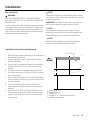
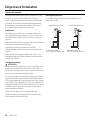
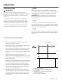
Horizontal discharge
A 90° elbow may be installed immediately above the
hood.
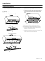
Roof Venting Wall Venting
A
B
A
B
A. Roof Cap
B.10” (25.4 cm)
Round Vent
A.Wall Cap
B.10” (25.4 cm)
Round Vent

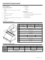
ENGLISH10
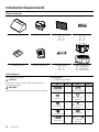
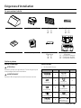
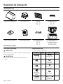
What is in the box
Hood assembly (1) 10" Transition (1) Filters
30” (2)
36” (2)
48” (3)
Drip trays
30” (2)
36” (2)
48” (3)
Single fan
Double fan
Hardware bag (1) Product literature (2) Drip tray bracket
30” (1)
36” (1)
48” (2)
Motor fan assembly
30" (Single fan)
36" (Double fan)
48" (Double fan)
Tools and parts
Removing the packaging
CAUTION
Remove the carton carefully. Wear gloves to protect
against sharp edges.
WARNING
Remove the protective lm before putting into operation.
Parts supplied
• Hardware bag includes:
Part Qty Part Qty
6 x 80 mm 6Torx 20 adapter 1
6 x 16 mm 4Ø 6.4 x 11 mm
washers
4
4.2 x 19 mm 4
Ø 5.3 x 20 mm
washers
2
Drip tray screws 23.5 x 9.5 mm 4
10 x 60 mm 66 - 9 wire fan
connector
1
Installation Requirements

ENGLISH 11
Parts not supplied
Tools/materials required
• Level
• Drill with 1” (2.5 cm),1⁄8” (3.0 mm) and 5⁄8” (15.8 mm)
drill bits
• Pencil
• Wire stripper or utility knife
• Tape measure or ruler
• Pliers
• Caulking gun and weatherproof caulking compound
• Vent clamps
• Jigsaw
• Metal snips
• Screwdrivers:
- Phillips
- Flat - blade
Parts needed
• Home power supply cable
• ½” (12.7 mm) UL listed or CSA approved strain relief
• 3 UL listed wire connectors
• 1 wall or roof cap
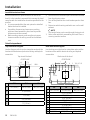
• Metal vent system
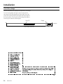
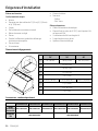
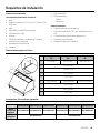
Dimentions and clearances
AB
E
G
H
I
F
D
C
30" 36" 48"
A 30" (76 cm) 36″ (91.2 cm) 48" (121.7 cm)
B25″ (63.2 cm)
C18″ (45.7 cm)
D12″ (30.5 cm)
E2³⁄₄″ (7 cm)
F29¹⁄₈" (74 cm) 35¹⁄₈″ (89.2 cm) 47¹⁄16" (119.6 cm)
G7¹⁄₂″ (19 cm)
H2⁹⁄₁₆″ (6.5 cm)
I³⁄₈″ (1 cm)
Accessories - Sold Separately
DHD30U990CS/DA DHD36U990CS/DA DHD48U990CS/DA DHD30U990CM/DA DHD36U990CM/DA DHD48U990CM/DA
Duct Cover
Kit DHD-D3020CS/DA DHD-D3620CS/DA DHD-D4820CS/DA DHD-D3020CM/DA DHD-D3620CM/DA DHD-D4820CM/DA
Extension
Kit DHD-D0000CS/DA DHD-D0000CM/DA
Installation Requirements

ENGLISH12
Installation
Installation instructions
We recommend that a qualied technician install the
hood. It is the installer’s responsibility to ensure the hood
complies with the installation clearances specied for the
product.
• It is recommended that the vent system be installed
before the hood is installed.
• If possible, disconnect and remove any cooking
appliance from beneath the hood area to provide
easier access to the rear wall.
• Before making cutouts, make sure there is proper
clearance within the ceiling or wall for the exhaust
vent.
• Conrm that all installation parts have been removed
from the shipping carton.
1. Turn off the power at the circuit breaker panel or fuse
box.
2. Determine which venting method to use: roof or wall
exhaust.
NOTE
This hood is factory set to vent through the top air exit.
3. Select a at surface for assembling the hood. Place a
covering over that surface.
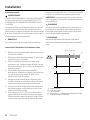
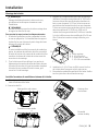
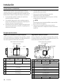
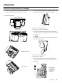
Outside top exhaust
Top installation diagram
Use the diagram or the hood as a template and mark the
locations for the ductwork, electrical wiring and keyhole
screw slots.
Top view of the hood
A
D
C
B
E
FRONT OF THE HOOD
5 1⁄4”
(13.3 cm) 5 1⁄4”
(13.3 cm) WALL
3⁄4” (19 mm)
10 1⁄2”
(26.6 cm)
CENTERLINE
30" 36" 48"
A 30" (76 cm) 36″ (91.2 cm) 48" (121.7 cm)
B12″ (30.5 cm)
C1″ (2.5 cm)
D2 ⁵⁄₈″ (6.5 cm)
E7 ¹⁄₂″ (19 cm)
Rear installation diagram
Use the diagram or the hood as a template and mark the
locations on the wall for electrical wiring and keyhole
screws slots.
Back view of the hood
Ø 1”
2.5 cm
B B
A
CCD
EE
F
G
H
I
TOP OF TH
E
HOOD
J
D
CENTERLINE
BOTTOM OF THE HOOD
30" 36" 48"
A 30" (75.5 cm) 36″ (90.6 cm) 48" (121.1 cm)
B9 ¹³/₁₆" (25 cm)
C3 ¹⁵/₁₆" (10 cm)
D3 ⁵/₈" (9.2 cm)
E3 ⁷/₁₆" (8.7 cm)
F 2" (5 cm)
G3 ¹/₄" (8.2 cm)
H3 ¹¹/₁₆" (9.3 cm)
I11 ³/₈" (28.9 cm)
J9 ⁵/₈" (24.5 cm) 12 ⁵/₈" (32 cm) 18 ⁵/₈" (47.3 cm)

ENGLISH 13
Installation
Wall installation
WARNING
USE TWO OR MORE PEOPLE TO MOVE AND INSTALL
THE HOOD. FAILURE TO DO SO CAN RESULT IN BACK OR
OTHER INJURY.
The hood is attached to the wall with a wood support that
is attached to the inside back of the hood. To support the
hood safely, the wood support must be xed rmly to at
least 2 vertical wooden studs that are located behind the
sheetrock that makes up the wall.
NOTE
These instructions are not applicable to masonry (brick,
concrete, etc.) walls. If you have a masonry wall, consult a
professional installer.
IMPORTANT: The studs (or wall if you have a masonry
wall) must be capable of supporting up to 150 lbs.
NOTE
If your kitchen has wood framing, at least 2 screws
provided for mounting this hood must be fastened into
solid wood studs. Do not fasten into sheetrock only.
NOTE
Mark the hood knockouts on the wall and make the
necessary cutouts before installing the hood.
Installation instructions for wood framing
1. Determine and mark the centerline on the wall where
the hood will be installed.
2. Select a mounting height “X” for the bottom of the
hood (See D below).
• For gas cooking installations: Mount the hood so the
bottom is at least 30”(76.2cm) above the cooking
surface.
• For electric/induction cooking installations: Mount
the hood so the bottom is at least 24”(60.9cm) above
the cooking surface.
3. Mark a horizontal reference line on the wall (B below)
for the bottom of the hood. Use a level to conrm that
the line is leveled.
4. Find and mark the location of the wood studs or
wood supports behind the wall. See rear installation
diagram.
5. Draw a line 15 ³⁄₈” (39.3 cm) above the reference line
for the bottom of the hood to mark the wood support
location on the wall. Use a level to conrm that the
line is leveled.
A
B
D
E. Ø 1” (2.5 cm)
C
“X”
A. Wood support
B. Bottom of hood
C. Center Line
D. Dimension “x” = hood mounting height
E. Knockout wiring holes

ENGLISH14
Installation
6. Remove the wood support from the back of the hood
by loosening the 2 screws from the inside.
7. Line the top of the wood support up with the wood
support location line on the wall, and then center it
on the center line.
8. Locate the marks for the studs on the wood support,
and then draw two vertical lines marking where the
studs intersect with the wood support.
9. Mark the center of each line, remove the wood
support from the wall, and then drill a pilot hole on
the support at each mark.
10. Again, line the top of the wood support up with the
wood support location line, and then center it on the
centerline.
11. Push a pencil point or awl through the holes you just
drilled in the wood support to mark on the wall the
location of the pilot holes for 2 - 6 x 80 mm screws
that will go into the studs.
12. Also mark on the wall the locations of two additional
pilot holes (B) by pushing a pencil point or awl
through pre-drilled holes in the center of the wood
support. These holes are for the supplied 2 - 10 x 60
mm wall anchors. See the diagram below.
C
B
A
1 ³⁄₁₆” (3 cm)
1 ³⁄₁₆”
(3 cm)
1 ” (2.5 cm)
1 ” (2.5 cm)
A. Screw holes
B. Screw holes (already made)
C. Wood Support
13. Remove the wood support, and then drill four pilot
holes into the wall.
14. Push 2 - 10 x 60 mm of the supplied wall anchors into
the two pilot holes at the center.
15. Fasten the wood support to the wall by screwing 2- 6
x 80 mm xing screws through the wood support into
the pilot holes you drilled in the studs.
16. Using the rear installation diagram as a guide (see
page 12), cut the knockout wiring holes in the wall.
17. Screw 2 - 6 x 80 mm screw (mounting screws) into
the holes (B) in the center of the wood support.
Screw them through the support into the anchors
underneath. Leave a ¹⁄₄”(6.4 mm) gap between the
wall and the back of the screw head to slide the hood
into place.
¹⁄₄” (6.4 mm)
15 ¹⁄₁₆” (38.5 cm)
NOTE
Once the hood is mounted you must tighten these
screws.

ENGLISH 15
Installation
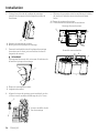
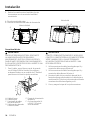
Complete preparation
1. Determine and make all necessary cuts in the wall
or roof for the vent system. Install the vent system
before installing the hood. See the “Venting Methods”
section.
2. Determine the location where the power supply cable
will be run through the wall.
3. Drill a 1” (2.5 cm) hole at this location.
4. Pull enough power supply cable through the wall to
allow for easy connection to the terminal box.
5. Remove the terminal box cover and set aside.
A. Terminal box cover
B. Knockout
C. Power supply wire connector
A
B
C
Single fan model
C
A
B
Double fan model
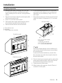
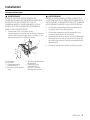
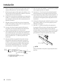
6. For all hood models install the 10” (25.4 cm) round
vent transition with damper to the top of the hood
(depending on your installation), using 4-3.5x9.5
mm screws.
7. Remove the knockout from the back of the hood and
install a UL listed or CSA approved ¹⁄₂”(1.3cm) strain
relief.
All hood models
A. 4 - 3.5 x 9.5 mm screws
B. Knockout
C. Mounting screws slot
D. 4 - 4.2 x 19 mm screws slots
E. 2 - 6 x 80 mm screws slots
A
A
B
C
D
E
D
NOTE
The exhaust adaptor/damper can be installed up to 1
inch on either side of the hood center to accomodate
off-center ductwork.
In extreme off-center installations, one end of the
duct connector may need to be trimmed to clear the
electrical cable clamp.
8. Place the hood near its mounting position and run the
power supply cable through the strain relief into the
terminal box (enough to make connection).
9. Tighten the strain relief screws.
10. Make the electrical connection. See the “Electrical
connection” section (p.18).

ENGLISH16
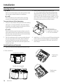
Mounting the hood
NOTE
Mark the hood knockouts on the wall, and then make
the necessary cutouts before the installation.
NOTE
The hood attaches to the wall by the 6 mounting
screws in the wood support mounted to the wall.
To mount the hood, follow these steps:
1. Using 2 or more people, hang the hood on the wall by
placing the 2 screws mounted in the wood support
attached to the wall through the wide portion of the
slotted holes in the back of the hood.
NOTE
If your installation uses the optional duct cover, the
vent system needs to be connected to the hood and
the duct cover mounted to the top of the hood before
you tighten the mounting screws.
2. Pull the hood down so the screws protrude through
the narrow portions of the slots, align the bottom
of the hood with the horizontal line marking the
hood bottom, level the hood, and then tighten the 2
mounting screws.
3. Mark 2 lower mounting hole locations. Drill
¹⁄₈” (0.32cm) pilot holes if the holes will be drilled
into wood studs or framing. If the holes will not be
drilled into wood, drill two ³⁄₈” (0.95 cm) pilot holes
and insert 10 x 60 mm wall anchors. Install 2-6x80
mm screws with 5.3 x 20 mm washers (D and C) into
the lower mounting holes, and then tighten.
B
B
A
C
A. Mounting screws
B. 4 - 4.2 x 19 mm screws
C. 2 - 6 x 80 mm screws with
2 - 5.3 x 20 mm washers
4. Install the 4 - 4.2 x 19 mm screws (B) through the back
of the hood into the wood support, and then tighten.
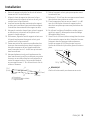
5. Connect the vent system to the hood. Seal all joint
with clamps.
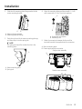
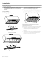
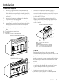
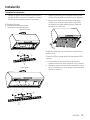
Install hood internal fan motor
1. Place the hood fan motor assembly inside the hood.
A. Wire connection
Single motor assembly
A
Double motor assembly
A
Single motor
assembly
Double motor
assembly
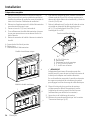
Installation

ENGLISH 17
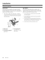
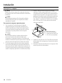
2. Slide the left mounting plate ange under the fan
motor mounting bracket.
AB
A. Motor mounting bracket
B. Mounting plate left flange
3. Push the right end of the motor mounting plate up,
and then snap it into the spring tab.
NOTE
The spring tab should be outside the slot in the
mounting plate.
A
B
A. Motor mounting plate
B. Spring tab
4. Align the mounting holes and then install 4 - 6 x 16
mm screws with 4 - 6.4 x 11 mm lock washers.
B
A
A. Screw with lock washer
B. Mounting hole
5. Make the connection between the fan and the
terminal box with the supplied wire fan connector.
A. Motor mounting plate
B. Power supply wire fan connector
Single motor assembly
B
A
Double motor assembly
A
B
Installation

ENGLISH18
Electrical connection
WARNING
ELECTRICAL SHOCK HAZARD. DISCONNECT POWER
BEFORE SERVICING. REPLACE ALL PARTS AND PANELS
BEFORE OPERATING. FAILURE TO DO SO CAN RESULT IN
DEATH OR ELECTRICAL SHOCK.
1. Run 3 wires - black, white, and green - according
to the National Electrical Code and local codes and
ordinances, in ¹⁄₂″ conduit from the service panel to
the terminal box.
DE
F
B
C
A
A. White wires
B. Black wires
C. UL listed wire connectors
D. Green, bare or yellow/
green wires
E. Home power supply
F. UL listed or CSA
approved ¹⁄₂” (1.3 cm)
strain relief
WARNING
ELECTRICALLY GROUND THE FAN. CONNECT THE
GROUND WIRE TO THE GREEN AND YELLOW GROUND
WIRES IN THE TERMINAL BOX. FAILURE TO DO SO CAN
RESULT IN DEATH OR ELECTRICAL SHOCK.
2. Use UL listed wire connectors and connect black
wires (B) together.
3. Use UL listed wire connectors and connect white
wires (A) together.
4. Connect green (or bare) ground wire from home
power supply to the green/yellow ground wire (D) in
terminal box using UL listed wire connectors.
5. Close and secure the terminal box cover.
Installation

ENGLISH 19
Installation
Completing the installation
1. Place the drip tray bracket over the hood back lter
support and place 2 drip tray screws on the slots.
A. Drip trays
B. Drip tray bracket
C. Drip tray screws
Single motor assembly
C
B
A
Double motor assembly
A
B
CC
2. Grasp the lter handles with both hands and then
place the front edge of the lter into the hood.
3. Push up on the back of the handle, and then set rear
of lter into the drip tray to secure. Repeat for each
lter.
1
2
Model shown for reference only, features may vary
Place the lters and check the operation of the hood.
• To get the most efcient use from your new hood,
read the “Use and Care” manual.
• Keep these Installation Instructions and Use and Care
Guide close to hood for easy reference.

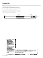
ENGLISH20
Attach Dacor badge
Use the template on this page for alignment of the badge.
Cut out the template and tape it onto the hood front
surace and verify the template is aligned with the right
side of the hood and within the upper and lower edge of
the front surface. Practice placing the badge rst before
removing the adhesive release paper.
Strip LEDBadge
Tem
plate
Front view of the hood
Installation
La page est en cours de chargement...
La page est en cours de chargement...
La page est en cours de chargement...
La page est en cours de chargement...
La page est en cours de chargement...
La page est en cours de chargement...
La page est en cours de chargement...
La page est en cours de chargement...
La page est en cours de chargement...
La page est en cours de chargement...
La page est en cours de chargement...
La page est en cours de chargement...
La page est en cours de chargement...
La page est en cours de chargement...
La page est en cours de chargement...
La page est en cours de chargement...
La page est en cours de chargement...
La page est en cours de chargement...
La page est en cours de chargement...
La page est en cours de chargement...
La page est en cours de chargement...
La page est en cours de chargement...
La page est en cours de chargement...
La page est en cours de chargement...
La page est en cours de chargement...
La page est en cours de chargement...
La page est en cours de chargement...
La page est en cours de chargement...
La page est en cours de chargement...
La page est en cours de chargement...
La page est en cours de chargement...
La page est en cours de chargement...
La page est en cours de chargement...
La page est en cours de chargement...
La page est en cours de chargement...
La page est en cours de chargement...
La page est en cours de chargement...
La page est en cours de chargement...
La page est en cours de chargement...
La page est en cours de chargement...
-
 1
1
-
 2
2
-
 3
3
-
 4
4
-
 5
5
-
 6
6
-
 7
7
-
 8
8
-
 9
9
-
 10
10
-
 11
11
-
 12
12
-
 13
13
-
 14
14
-
 15
15
-
 16
16
-
 17
17
-
 18
18
-
 19
19
-
 20
20
-
 21
21
-
 22
22
-
 23
23
-
 24
24
-
 25
25
-
 26
26
-
 27
27
-
 28
28
-
 29
29
-
 30
30
-
 31
31
-
 32
32
-
 33
33
-
 34
34
-
 35
35
-
 36
36
-
 37
37
-
 38
38
-
 39
39
-
 40
40
-
 41
41
-
 42
42
-
 43
43
-
 44
44
-
 45
45
-
 46
46
-
 47
47
-
 48
48
-
 49
49
-
 50
50
-
 51
51
-
 52
52
-
 53
53
-
 54
54
-
 55
55
-
 56
56
-
 57
57
-
 58
58
-
 59
59
-
 60
60


Dacor DHD48U990CS Guide d'installation
- Catégorie
- Hottes
- Taper
- Guide d'installation
- Ce manuel convient également à
dans d''autres langues
- English: Dacor DHD48U990CS Installation guide
- español: Dacor DHD48U990CS Guía de instalación