SIONYX OPSIN MDV-400C Night Vision Camera Manuel utilisateur
- Taper
- Manuel utilisateur


SIONYX, LL C
OPSIN
Made In Indonesia
SIONYX.com/patents
NEED HELP
ONLINE CHAT
SUBMIT A TICKET
24/7 SUPPORT
CALL
www.sionyx.com
www.sionyx.com/contact
www.support.sionyx.com
(866) 827-8237
Register your device and
stay up to date by visiting
the URL or scanning the
QR code below.
SIONYX LLC
Cummings Center
Beverly, MA 01915
U.S.A.
(978) 922-0684
support@SIONYX.com
FOLLOW US
Share your SIONYX content and be sure to tag us!


2SIONYX OPSIN USER MANUAL
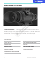
WELCOME TO OPSIN
OPSIN
MDV-400C
BATTERY PACK
BATTERY CABLE
BATTERY CHARGER
HELMET MOUNT QUICK-RELEASE
BOX INCLUDES:
THIS IS SIONYX We believe that human endeavor should not be
limited by daylight. In the darkness of night, greatness is possible . Adventure
enabled. And a full sense of all sight achievable, no matter the light.
SOFT CARRY/STORAGE CASE
EYE CUP
LENS CAP AND TETHER
QUICK START GUIDE

3
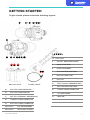
To get started, please review the following legend
GETTING STARTED
BUTTONS1-3
OBJECTIVE LENS5
POWER CABLE
BATTERY PACK
GETTING STARTED
14131211109
8 7
6
45 3 12
ON/OFF, BRIGHTNESS KNOB4
LENS FOCUS RING6
EVF DIOPTER ADJUST RING7
MICROPHONE PORT8
EYE CUP9
ELECTRONIC VIEWFINDER (EVF)10
EVF DIOPTER ADJUST RING11
POWER CABLE CONNECTOR12
SD CARD COVER13
MINI RAIL14
171615
7
1918
BATTERY LEVEL INDICATOR15
BATTERY LEVEL BUTTON16
BATTERYTERMINAL (WATERPROOF)17
CAMERA CABLE CONNECTOR18
BATTERY CABLE CONNECTOR19
EYE PIECE BUMPERNot Shown
LENS CAP & TETHERNot Shown

SIONYX OPSIN USER MANUAL 4
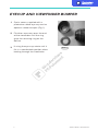
EYECUP AND VIEWFINDER BUMPER
FIG. 1
Opsin comes supplied with a
protective rubber eye-cup and an
optional rubber bumper. (Fig. 1)
1
Fit either accessory over the end
of the viewfinder until the ring
grips the retaining ring on the
device.
2
If using the eye cup, rotate until it
fits in a comfortable position when
looking through the viewfinder
3

SIONYX OPSIN USER MANUAL
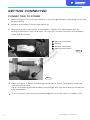
GETTING CONNECTED
CONNECTING TO POWER
Attach the battery connector to the battery. Tighten the connector cover by
turning it clockwise until hand-tight. This ensures a water resistant seal between
cable and the battery
3
Refer to Figure 3. Attach the locking connector to Opsin. To properly make the
connection the white
dot on the locking connector body should align with the white dot on the device
connector body
3
FIG.2
IBattery
II Battery connector
III Locking connector
IV Device connector
Refer to Figure 2. Ensure your battery is fully charged before attempting to connect
to your device
1
Remove the Battery Pack charge port cap
2
Push the two halves of the connector together until you hear an audible ‘click’
4
FIG. 3
5

SIONYX OPSIN USER MANUAL
6
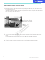
DISCONNECTING THE BATTERY
Refer to Figure 4. With one hand firmly gripping the device, use your thumb and
first finger to pull the
rotating connector sleeve upwards away from the camera and pull. The connector
will snap away from the device.
1
Carefully stow the cable and the battery in the battery pouch provided.
3
Unscrew the battery connector (turn counter-clockwise) and replace the plastic
cover
on the battery to protect its terminals from possible damage or debris.
2
FIG. 4
IConnector Sleeve
II Battery Connector

SIONYX OPSIN USER MANUAL 7
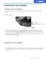
OPERATING THE CAMERA
TURNING ON THE CAMERA
TURNING OFF THE CAMERA
Ensure the camera is connected to the battery pack according to the steps on
Page 4
1
Look through the viewfinder and check that turning the power/brightness knob
results in an image displayed on the screen. The camera takes a few seconds to
boot up. Turning the knob controls the display brightness of the screen. To make
the display brighter turn the knob clockwise. To make the display dimmer turn the
knob counter-clockwise.
3
FIG. 5
Turn the knob clockwise until the knob clicks. The camera is turned off, however it
is safest to disconnect the battery cable and store the battery when not using the
camera.
1
II Power/Brightness Knob
IViewfinder
Refer to Figure 52

SIONYX OPSIN USER MANUAL 8
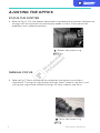
AJUSTING THE OPTICS
MANUAL FOCUS
FOCUS THE DIOPTER
Refer to Fig. 6. Turn the diopter adjustment ring clockwise or counter clockwise to
change until the characters on the display appear in focus. Each person will
probably have a different position.
1
Refer to Fig. 7. Focus the lens to the subject by turning the manual focus
adjustment. Turning the ring clockwise brings closer subjects into focus and
turning the ring counter clockwise brings far away subjects into focus.
1
IDiopter adjustment ring
IFocus adjustment ring
FIG. 6
FIG. 7

9
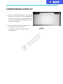
VIEWFINDER DISPLAY
FIG. 8
Opsin's viewfinder displays the image
seen by the camera. The top edge of
the display shows critical information
such as battery life GPS position and
compass heading
1
For detailed description of each of
the features shown in the
viewfinder see the section titled
"Using Opsin"
2

10
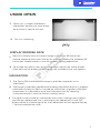
USING OPSIN
FIG. 8
Opsin has a number of different
capabilities besides live view of the
dark scene in front of the user.
1
This list is evolving
2
To change the refresh rate, press and quickly release the center button.
Each press of the button cycles through the available frame rate options.
2
Opsin can display the live camera image at 30, 60 or 90 frames per
second. Lowering the frame rate results in longer battery life, however 90
frames per second creates a real-life smooth viewing experience.
1
DISPLAY REFRESH RATE
The Opsin GPS and electronic compass provide navigation assist
information.
1
The compass provides approximate heading information once it is properly
calibrated. As long as Opsin is turned on it continues to gather calibration
information. It is possible to reset the calibration data by selecting
"calibrate compass" from the camera settings menu
2
The GPS can be turned on and off from the camera settings menu. When
the GPS has determined a fix, it will display the coordinates in the EVF
display. While it is obtaining the fix, the coordinates will be represented by
'-" for each coordinate value.
3
NAVIGATION

SIONYX OPSIN USER MANUAL
11
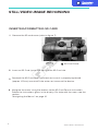
STILL/VIDEO IMAGE RECORDING
INSERTING/FORMATTING SD CARD
Insert an SD Card (up to 256 GB) into the SD Card slot
2
Navigate the menu using the buttons to the SD Card Format instruction.
Follow the instructions given in the display. For help with the menu see the
section
"Navigating the Menus" on page 10
4
Reattach the SD Card cover and check to insure it is properly tightened
(approx. 1/8 turn) to maintain the water resistance of the device.
3
FIG. 9
ISD Card Cover
Remove the SD card cover (refer to figure 7)
1

SIONYX OPSIN USER MANUAL
12
RECORDING A STILL PICTURE
RECORDING A VIDEO CLIP
FIG. 10
Refer to Figure 10 for position and
descriptions of the buttons.
1
To take a picture simply aim
the camera at the subject
and press the front button.
The picture is automatically
saved to the SD Card.
3
Refer to Figure 8 for position and
descriptions of the buttons.
1
To record a video clip simply aim the camera at the subject
and press the rear button to start the recording and press
again to stop the recording. The video clip is automatically
saved to the SD Card.
3
Opsin is not equipped with playback capability. Remove the SD Card and
load it into another device (e.g. PC) to view and save the captured images
and video files.
3
VEWING IMAGES


SIONYX OPSIN USER MANUAL
14
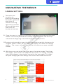
NAVIGATING THE MENUS
FIG. 9
The menus are
turned on by
pressing and holding
the center button for
more than 1.5
seconds. Pressing
again for 1.5 seconds
will turn off the menu
and return the
function to live view
1
Once the menu is showing in the screen navigate using the forward and back
buttons.
The cursor points to the currently active menu item and will wrap
around to the
beginning or end with repeated button presses.
2
To select a settin g to adjust , press th e center butt on once quic kly (shor t press) to
navigate down a level . At that point the display will show the settings
options . The cursor will now point at the first of one or more available
choices.
3
With the cursor next to the new value. press the center button. Two things
will happen: 1) the camera will adopt the new value as its setting, and 2) the
menu will
disappear, returning the user to the live view mode. This allows
for quick changing of a few settings with minimal distraction to the user.
4
CAMERA SETTINGS

SIONYX OPSIN USER MANUAL
15
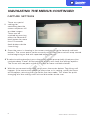
NAVIGATING THE MENUS CONTINUED
There are special
settings for
controlling how the
camera captures still
or video images.
These can be
reached by pressing
either the forward or
back button for more
than 1.5 seconds
(both buttons do the
same thing)
1
Once the menu is showing in the screen navigate using the forward and back
buttons. The cursor points to the currently active menu item and will wrap around
to the beginning or end with repeated button presses.
2
To s e l ec t a s e tt i ng to ad ju s t, p re ss th e c en te r b u t to n o n c e q u ic k ly (s h o rt p re ss ) t o
navigate down a level. At that point the display will show the settings options.
The cursor will now point at the first of one or more available choices.
3
With the cursor next to the new value. press the center button. Two things will
happen: 1) the camera will adopt the new value as its setting, and 2) the menu
will disappear, returning the user to the live view mode. This allows for quick
changing of a few settings with minimal distraction to the user.
4
CAPTURE SETTINGS

SIONYX OPSIN USER MANUAL
16
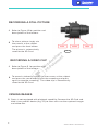
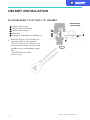
HELMET INSTALLATION
ACCESSORIES TO ATTACH TO HELMET
FIG.9
VI Dovetail, Rhino Mount (Optional)
IV Mini Rail
III Adjustment Screw
II Quick Release Button
IPower Connector
Refer to Figure 11. Assemble an
appropriate flip-style helmet
mount if necessary. Cables must
be routed correctly, to maximize
performance and prolong cable
life.
• Do NOT bend cables
excessively
1
I
II
IV
III
V
VI

SIONYX OPSIN USER MANUAL
17
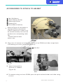
ACCESSORIES TO ATTACH TO HELMET
FIG. 8
FIG. 10
VRhino Mount (Optinal)
IV Dovetail Rail
III Adjustment Screw
II Quick Release Button
1Mini Rail Mount
Refer to Figure 10. Assemble an
appropriate flip-style helmet
mount if necessary. Cables must
be routed correctly, to maximize
performance and prolong cable
life.
• Do NOT bend cables
excessively
1
Align mini rail receiver of swing arm to mini rail on OPSIN and slide straight back
until locking arm clicks into place (Figure 11)
2
FIG 11
Adjust interpupillary
distance as needed.
(Figure 12)
3
FIG 12.
IMini Rail
To remove swing arm from OPSIN, press the quick release button and slide swing
arm out
4

18 SIONYX OPSIN USER MANUAL
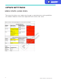
SAFETY
IMPORTANT PRODUCT AND SAFETY INSTRUCTIONS
WARNING
Failure to properly set up, use, and care for this product can increase the
risk of serious injury, death, property damage, or damage to the product
or related accessories. Exercise caution when using a SIONYX product as
part of your active lifestyle. Always be aware of your surroundings to
avoid injury to yourself and others.
1. Product shall be used in accordance with all manufacturing instruction and
limits.
2. Read all provided documentation, and keep it for future reference.
3. Follow all instructions and heed all warnings.
4. Properly install, use, and maintain all power and data cable as per
manufacturing specification.
5. Only use attachments and accessories specified and/or approved by
SIONYX.
6. SIONYX OPSIN is designed to be serviced only by qualified service
personal.
Visit SIONYX.com for more information.
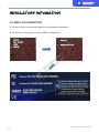
Hereby, SIONYX, LLC declares that the radio equipment type SIONYX
OPSIN is in compliance with Directive 2014/53/EU. Visit WWW.SIONYX.
com/support for full documentation and company contact information
The SIONYX OPSIN camera transmits at 2.412 GHz – 2.462 GHz. The
maximum
power transmitted in this frequency band is EIRP 16.97 dBm.
Country specific rules and regulations can prevent or limit the use of
some or all the listed frequency
bands and power level.
The use of this product is an acknowledgment and agreement to all the
product
instruction, safety warnings, private policy and other pertaining
documentation
outlined or reference in this document.
THIS DOCUMENT CONTAINS IMPORTANT SAFETY AND
HEALTH INFORMATION THAT MUST BE READ BEFORE
USE.
La page est en cours de chargement...
La page est en cours de chargement...
La page est en cours de chargement...
La page est en cours de chargement...
La page est en cours de chargement...
La page est en cours de chargement...
La page est en cours de chargement...
La page est en cours de chargement...
La page est en cours de chargement...
-
 1
1
-
 2
2
-
 3
3
-
 4
4
-
 5
5
-
 6
6
-
 7
7
-
 8
8
-
 9
9
-
 10
10
-
 11
11
-
 12
12
-
 13
13
-
 14
14
-
 15
15
-
 16
16
-
 17
17
-
 18
18
-
 19
19
-
 20
20
-
 21
21
-
 22
22
-
 23
23
-
 24
24
-
 25
25
-
 26
26
-
 27
27
-
 28
28
-
 29
29


