Cosmo COS-305DFSC Manuel utilisateur

Catégorie
Cuisinières
Taper
Manuel utilisateur
INSTALLATION Instructions
INSTRUCTIONS d’installation
30 IN. DUAL FUEL
FREE- STANDING RANGE
CUISINIÈRE AUTOPORTANTE
À BI-COMBUSTIBLE DE 30 PO
COS-305DFSC
I N S P I R I N G T H E W O R L D ’ S K I T C H E N
IMPORTANT SAFETY INSTRUCTIONS
Carefully read the following Important information redarding installation
safety and maintenance. Keep these instruction for future reference.
RANGE SAFETY . ..........................................................................................................
I
NSTALLATION REQUIREMENTS ...............................................................................
Tools and Parts ..........................................................................................................
Location Requirements ..............................................................................................
Electrical Requirements .............................................................................................
Gas Supply Requirements .......................................................................................
I
NSTALLATION INSTRUCTIONS ...............................................................................
Step 1 - Unpack Range ...........................................................................................
Step 2 - Install Anti-Tip Bracket ...............................................................................
Step 3 - Make Electrical Connection ........................................................................
Step 4 - Make Gas Connection .................................................................................
Step 5 - Install Range ...............................................................................................
G
AS CONVERSION ...................................................................................................
Step 1 - Adjust the Gas Pressure Regulator .............................................................
Step 2 - Change Burner Oriÿces ...............................................................................
Step 3 - Adjust Burner Flames .................................................................................
Step 4 - Testing Flame Stability ................................................................................
Step 5 - Flame Re-Check ..........................................................................................
Table of Contents
1
THANK YOU FOR YOUR PURCHASE.
Thank you for your purchase. We know that you have many brands and
products to choose from and we are honored to know that you have decided
to take one of our products into your home and hope that you enjoy it.
COSMO appliances are designed according to the strictest safety and performance
standard for the North American market. We follow the most advanced
manufacturing philosophy. Each appliance leaves the factory after thorough
quality inspection and testing. Our distributors and our service partners are
ready to answer any questions you may have regarding how to install, use and
care for your products. We hope that this manual will help you learn to use the
product in the safest and most effective manner .
If you have any questions or concerns, please contact the dealer from whom you
purchased it, or contact our Customer Support at:
1-888-784-3108.
Please read the important safety instructions before using our product for
your own safety and to reduce the risk of fire or electrical shock, etc.
Please keep this manual for future use.
THANK YOU
INSTRUCTIONS D’INSTALLATION............................................................ 31
4
7
7
8
11
13
16
16
17
18
22
23
25
27
28
29
30
30
2 3
Range Safety
Your safety and the safety of others are very important.
We have provided many important safety messages in this manual
and on your appliance. Always read and obey all safety messages.
DANGER
WARNING
CAUTION
This is the safety alert symbol.
This symbol alerts you to potential hazards that can
kill or hurt you and others. All safety messages will
follow the safety alert symbol and either the word
“DANGER,” “WARNING” or “CAUTION.”
These words mean:
An imminently hazardous situation. You
could be killed or seriously injured if
you don’t immediately follow instructions.
A potentially hazardous situation which, if
not avoided, could result
in death or serious bodily injury.
A potentially hazardous situation
which, if not avoided, may result
in moderate or minor injury.
All safety messages will tell you what the potential hazard is, tell
you how to reduce the chance of injury, and tell you what can
happen if the instructions are not followed.
2
Fire Hazard
If the information in this manual is not followed exactly, a are
or explosion may result causing property damage, personal
injury or death.
- Do not store or use gasoline or other flammable vapors and liquids in
the vicinity of this or any other appliance.
- WHAT TO DO IF YOU SMELL GAS
Do not try to light any appliance.
Do not touch any electrical switch.
Do not use any phone in your building.
Clear the room, building, or area of all occupants.
Immediately call your gas supplier from a neighbor’s phone.
Follow the gas supplier’s instructions.
If you cannot reach your gas supplier, call the fire department.
- Installation and service must be performed by a qualified installer,
service agency or the gas supplier.
WARNING: Gas leaks cannot always be detected by smell.
Gas suppliers recommend that you use a gas detector approved
by UL or CSA.
For more information, contact your gas supplier.
If a gas leak is detected, follow the “What to do if you smell
gas” instructions.
WARNING
Range Safety
3
4 5
In the State of Massachusetts, the following installation
instructions apply:
Installations and repairs must be performed by a qualified or
licensed contractor, plumber, or gasfitter qualified or licensed by
the State of Massachusetts.
If using a ball valve, it shall be a T-handle type.
A flexible gas connector, when used, must not exceed 3 feet.
A child or adult can tip the range and be killed.
Connect anti-tip bracket to rear range foot.
Reconnect the anti-tip bracket, if the range is moved.
Failure to follow these instructions can result in death or serious
burns to children and adults.
WARNING: This product contains one or more chemicals known
to the State of California to cause cancer.
WARNING: This product contains one or more chemicals known to
the State of California to cause birth defects or other reproductive
harm.
State of California Proposition 65 Warnings:
T
ip Over Hazard
WARNING
Range Safety
4
5
TOOLS AND PARTS
Gather the required tools and parts before starting installation. Read and follow
the instructions provided with any tools listed here.
TOOLS NEEDED
Tape measure
Flat-blade screwdriver
Phillips screwdriver
Level
Cordless electric drill
Hammer
Wrench or pliers
Pipe wrench
10" Adjustable Wrenches (2)
3/8" nut driver
¼" nut driver
1/8" (3.2 mm) drill bit (for wood floors)
Marker or pencil
Masking tape
Pipe-joint compound resistant to LP gas
a/16" carbide-tipped masonry drill bit
(for concrete ceramic floors)
Noncorrosive leak-detection solution
F
or LP/Natural Gas Conversions
½" Combination wrench
7 mm combination wrench
7 mm nut driver
PARTS SUPPLIED
c
d
a 16 x 1 5/8" Screws (2)
b Anti-tip Bracket
c Regulator
d Gas Pipe Adapter
with Washer
e LP/Natural Gas
Conversion Kit
N
OTE: The Anti-tip bracket must be securely mounted to the subfloor.
Depending on the thickness of the flooring, longer screws may be
required to anchor the anti-tip bracket to the subfloor. Longer screws are
available from your local hardware store.
Installation Requirements
6 7
6
PARTS NEEDED
Check local codes and consult gas supplier. Check existing gas supply and
electrical supply. See “Electrical Requirements” and “Gas Supply
Requirements” sections.
Gas Supply Line Kit (Supply line and 2 adapters)
LOCATION REQUIREMENTS
VENTILATION
IMPORTANT: Observe all governing codes and ordinances. Do not obstruct
flow of combustion and ventilation air.
It is the installer’s responsibility to comply with installation clearances if
specified on the model/serial rating plate. The model/serial rating plate is
located on the left-hand side of the oven frame. Open oven door to view
label. See label on back panel of range for additional element and oven
power ratings.
a
a Rating Plate
TEMPERATURE
IMPORTANT: Some cabinet and building materials are not designed to
withstand the heat produced by the oven for baking and self-cleaning. Check
with your builder or cabinet supplier to make sure that the materials used will
not discolor, delaminate or sustain other damage.
Contact a qualified floor covering installer to check that the floor covering
can withstand at least 200°F (93°C).
Use an insulated pad or ¼" (0.64 cm) plywood under range if installing range
over carpeting.
Installation Requirements
7
GENERAL
The range should be located for convenient use in the kitchen.
Recessed installations must provide complete enclosure of the sides and
rear of the range.
To eliminate the risk of burns or fire by reaching over heated surface units,
cabinet storage space located above the surface units should be avoided. If
cabinet storage is to be provided, the risk can be reduced by installing a
range hood or microwave hood combination that projects horizontally a
minimum of 5" (12.7 cm) beyond the bottom of the cabinets.
All openings in the wall or floor where range is to be installed must be sealed.
Do not seal the range to the side cabinets.
Grounded electrical supply is required. See “Electrical Requirements” section.
Proper gas supply connection must be available. See “Gas Supply
Requirements” section.
DIMENSIONS
Product/Opening
Opening dimensions shown are for 25" (64.0 cm) countertop depth, 24" (61.0
cm) base cabinet depth and 36" (91.4 cm) countertop height.
a
5.9" (15 cm)
Min.
b
c
ed
Dimension
a
30" (76 cm)
b
29 7/8" (75.9 cm)
c
25" (63.5 cm)
d
36" (91.4 cm)
e
37 3/4" (96 cm)
N
OTE: Range can be raised approximately 1" (2.5 cm) by adjusting the leveling
legs. Front of door and drawer may extend farther forward depending on styling.
Installation Requirements
Min. 24" (60.9 cm)
Max. 30" (77 cm)
8 9
Back of Range
a
b
c
a
Access Panel to Electrical
Supply Connection
b
Power Cord Opening
c
Recessed area
P
ower Supply
IMPORTANT: An electrical outlet in the floor, may be either recessed or surface
mounted, but an electrical outlet in the wall must be recessed to make the
connection. For Direct Wiring, the electrical box should be mounted to the wall.
a
b
e
d
g
h
c
f
a
30" (76 cm)
b
11½" (29.2 cm)
c
6" (15.2 cm)
d
7¼" (18.4 cm)
e
3" (7.6 cm)
f
17½" (44 cm)
g
Recommended Location for
Electrical Outlet
h
Recommended Location
for Gas Supply Connection
Installation Requirements
8
9
NOTE: 24" (61.0 cm) minimum when bottom of wood or metal cabinet is
covered by not less than ¹e" (0.64 cm) flame retardant millboard covered with
not less than No. 28 MSG sheet steel, 0.015" (0.4 mm) stainless steel,
0.024" (0.6 mm) aluminum or 0.020" (0.5 mm) copper. 30" (76.2 cm) minimum
clearance between the cooking and the bottom of an uncovered wood or metal
cabinet.
ELECTRICAL REQUIREMENTS
IMPORTANT: Use a 3-wire, UL listed, 30-amp minimum supply cord (pigtail);
or if local codes do not permit grounding through the neutral, use a 4-wire UL
listed, 30-amp minumum power supply cord rated at 250 volts and intended
for use with ranges.
If codes permit and a separate ground wire is used, it is recommended that
a qualified electrical installer determine that the ground path is adequate
and wire gauge is in accordance with local codes.
To properly install your range, you must determine the type of electrical
connection you will be using and follow the instructions provided for it here.
Range must be connected to the proper electrical voltage and frequency as
specified on the model/serial number rating plate. All models are dual rated,
and designed to be connected to either 120/240V or 120/208V AC, 60Hz,
single-phase, 3-wire or 4-wire, power supply.
Voltage and
Frequency
Amps Circuit Required
240V, 60 Hz 20A
25 Amp Circuit
208V, 60 Hz 17.4A
20 Amp Circuit
When a 4-wire, single-phase 120/240 volt, 60 Hz., AC only electrical
supply is available, a 25-amp maximum circuit protection is required (or, if
specified on the model/serial rating plate, when a 4-wire, single phase
120/208 volt 60 Hz., AC only electrical supply is available, a 20-amp
maximum circuit protection is required).
For direct wire installations, install a suitable conduit box (not furnished).
An appropriately sized, UL conduit connector must be used to correctly
attach the conduit to the junction box.
I
MPORTANT: Local Codes may vary; installation electrical connections
and grounding must comply with all applicable local codes.
If local codes permit grounding through the electrical supply neutral, connect
both the white neutral wire and the green ground wire from the oven to the
white neutral electrical supply wire.
ELECTRICAL REQUIREMENTS - U.S.A. ONLY
Do not use an extension cord.
Be sure that the electrical connection and wire size are adequate and in
conformance with the National Electrical Code, ANSI/ NFPA No. 70-latest
edition and all local codes and ordinances.
A copy of the above code standards can be obtained from:
National Fire Protection
Association One Batterymarch
Park
Quincy, MA 02269
Installation Requirements
10 11
11
A copy of the above code standards can be obtained from:
Canadian Standards
Association 178 Rexdale Blvd.
Toronto, ON M9W 1R3
CANADA.
Check with a qualified electrical installer if you are not sure the range is
properly grounded.
This range is equipped with a CSA International Certified Power Cord
intended to be plugged into a standard 14-50R wall receptacle. Be sure the
wall receptacle is within reach of range’s final location.
Do not use an extension cord.
GAS SUPPLY REQUIREMENTS
Explosion Hazard
Use a new CSA International approved gas supply line.
Install a shut-off valve.
Securely tighten all gas connections.
If connected to LP, have a qualified person make sure gas
pressure does not exceed 14" (36 cm) water column.
Examples of a qualified person include:
licensed heating personnel,
authorized gas company personnel, and
authorized service personnel.
Failure to do so can result in death, explosion or fire.
Observe all governing codes and ordinances.
Installation Requirements
WARNING
12 13
14 15
14
GAS SUPPLY PRESSURE TESTING
Line pressure testing above 0.5 psi gauge (14. WCP)
The range and its individual shutoff valve must be disconnected from the gas
supply piping system during any pressure testing of that system at test
pressures in excess of 0.5 psi (3.5 kPa).
L
ine pressure testing at 0.5 psi gauge (14" WCP) or lower
The range must be isolated from the gas supply piping system by closing its
individual manual shutoff valve during any pressure testing of the gas supply
piping system at test pressures equal to or less than 0.5 psi (3.5 kPa).
I
MPORTANT: This appliance shall be installed only by authorized persons
and in accordance with the manufacturer’s installation instructions, local
gas fitting regulations, municipal building codes, electrical wiring
regulations, local water supply regulations.
STEP 1 - UNPACK RANGE
Excessive Weight Hazard
Use two or more people to move and install range. Failure to
do so can result in back or other injury.
1. Remove shipping materials, tape and film from the range. Keep
cardboard bottom under range. Do not dispose of anything until the
installation is complete.
2
. Remove oven racks and parts package from oven and shipping materials.
3
. To remove cardboard bottom, first take 4 cardboard corners from the
carton. Stack one cardboard corner on top of another. Repeat with the
other 2 corners. Place them lengthwise on the floor behind the range to
support the range when it is laid on its back.
4
. Using two or more people, firmly grasp the range and gently lay it on its
back on the cardboard corners.
5
. Remove cardboard bottom.
N
OTES:
The leveling legs can be adjusted while the range is on its back.
To place range back up into a standing position, put a sheet of cardboard
or hardboard on the floor in front of range to protect the flooring. Using two
or more people, stand range back up onto the cardboard or hardboard.
Installation Requirements
Installation Instructions
WARNING
WARNING
15
STEP 2 - INSTALL ANTI-TIP BRACKET
Tip Over Hazard
A child or adult can tip the range and be killed.
Connect anti-tip bracket to rear range foot.
Reconnect the anti-tip bracket, if the range is moved.
Failure to follow these instructions can result in death or serious
burns to children and adults.
IMPORTANT: An anti-tip bracket kit is included with the range. The anti-tip bracket
uses either the right or left rear leveling leg to secure the range to the floor.
1. Remove the anti-tip bracket from where it is taped inside the oven or storage
drawer.
2. Determine and mark centerline of the opening.
NOTE: The anti-tip bracket can be installed on either the left-hand side or
right-hand side of the opening.
3. Place the anti-tip bracket onto the floor so that the distances from the
center of the bracket to the center line and to the wall is correct for your
model.
Center of Opening to Center of Bracket: 13½" (34.3 cm)
Wall to Top of Bracket - 35/16" (8.e cm)
4. Drill two 1/8" (3 mm) holes through the mounting holes in the anti-tip
bracket and into the floor.
NOTE: Contact a qualified floor covering installer for the best procedure
for drilling mounting holes through your type of floor covering.
5. Using the two screws provided, secure the anti-tip bracket to the floor.
NOTE: A rear leg of the range will be centered within the anti-tip bracket
when it is moved into its final position.
Installation Instructions
16 17
WARNING
16
STEP 3 - MAKE ELECTRICAL CONNECTION
After reading the requirements for each connection method, follow the
electrical connection instructions specific to your situation.
POWER SUPPLY CORD - CANADA ONLY
Electrical Shock Hazard
Plug into a grounded outlet.
Do not use an extension cord.
Failure to do so can result in death, re, or electrical shock.
1. Plug into a standard 14-50R grounded wall receptacle.
2
. Go to STEP 4 - MAKE GAS CONNECTION.
Installation Instructions
WARNING
17
DIRECT WIRE - U.S.A ONLY
Electrical Shock Hazard
Disconnect power before servicing.
Improper connection of aluminum house wiring and copper
appliance leads can result in an electrical hazard or fire. If the home
has aluminum wiring, only use connectors designed and UL listed
for joining copper to aluminum and precisely follow the
manufacturer's recommended procedure. Aluminum-to-Copper
connections must conform with local codes.
Use 10 gauge copper or aluminum wire.
Electrically ground range.
Failure to do so can result in death, fire or electrical shock.
Be sure your appliance is properly installed and grounded by a qualified
technician. Ask your dealer to recommend a qualified technician or an
authorized repair service.
This range is manufactured with a neutral (white) power supply wire and a
cabinet-connected green (or bare) ground wire twisted together.
After making sure that the power has been turned off, connect the flexible
conduit from the range to the junction box using a UL listed conduit connector.
The Grounded Neutral and Ungrounded Neutral Graphics on the following
pages and the instructions provided, present the most common way of
connecting ranges. Your local codes and ordinances, of course, take
precedence over these instructions. Complete electrical connections according
to local codes and ordinances.
Installation Instructions
18 19
WARNING
18
3-WIRE CONNECTION (GROUNDED NEUTRAL) - U.S.A. ONLY.
Electrical Shock Hazard
Grounding through the neutral conductor is prohibited for new
branch-circuit installations (1996 NEC); mobile homes; and
recreational vehicles, or in an area where local codes prohibit
grounding through the neutral conductor. For installations where
grounding through the neutral conductor is prohibited, see the
Ungrounded Neutral graphic.
Use grounding terminal or lead to ground unit.
Connect neutral terminal or lead to branch circuit neutral in
usual manner.
Failure to do so could result in death, fire or electric shock.
3-Wire Cable from Home Power Supply
IMPORTANT: Use the 3-wire cable from home power supply where local codes
permit a 3-wire connection.
1
. Disconnect power.
G
rounded Neutral
e
i
g
h
f
a
b
c
d
a Junction Box
b Black Wires
c Neutral (White)
Wires
d Ground (Green or
Bare) Wire
e Cable from Range
f UL Listed Conduit
Connector
g Red Wires
h UL Listed Wire Connectors
i House Electrical Supply
Installation Instructions
19
2.
Connect the 2 black wires
b together using a UL listed wire connector.
3
.
Connect the 2 neutral (white) wires
c and the ground (green or bare) wire d
(of the range cable) using a UL listed wire connector.
4
.
Connect the 2 red wires
g together using a UL listed wire connector.
5
. Install junction box cover.
4-WIRE CONNECTION (UNGROUNDED NEUTRAL)- U.S.A. ONLY
4-Wire Cable from Home Power Supply
IMPORTANT: Use the 4-wire cable from home power supply in the U.S. where
local codes do not allow grounding through neutral, New Branch circuit
installations (1996 NEC), mobile homes and recreational vehicles, new
construction and in Canada.
1
. Disconnect power.
U
ngrounded Neutral
i
b
c
d
g
f
e
h
a
a Junction Box
b Black Wires
c Red Wires
d Cable from Range
e UL listed or CSA
Approved Conduit
Connector
f Ground (Green or
Bare) Wires
g UL Listed Wire
Connector
h Neutral (White) Wires
i House Electrical Supply
2
.
Connect the 2 black wires b together using a UL listed wire connector.
3
.
Connect the 2 red wires
c together using a UL listed wire connector.
4
. Untwist white wire from green (or bare) ground wire coming from the range.
5
.
Connect the 2 neutral (white) wires
h together using a UL listed
wire connector.
6
.
Connect the ground (green or bare) wire
f from the oven cable to the
ground (green or bare) wire (in the junction box) using a UL listed wire
connector.
7
. Install junction box cover.
Installation Instructions
20 21
WARNING
STEP 4 - MAKE GAS CONNECTION
Explosion Hazard
Use a new CSA International approved gas supply line.
Install a shut-off valve.
Securely tighten all gas connections.
If connected to LP, have a qualified person make sure gas
pressure does not exceed 14" (36 cm) water column.
Examples of a qualified person include:
licensed heating personnel,
authorized gas company personnel, and
authorized service personnel.
Failure to do so can result in death, explosion or fire.
TYPICAL FLEXIBLE CONNECTION
CONNECT BSPP TO NPT ADAPTER TO GAS REGULATOR:
1. Apply pipe-joint compound made for use with LP gas to the male threads of
adapter
c
.
2
.
Insert adapter
c
into outlet of the gas pressure regulator
d
, and then
tighten using two 10" adjustable wrenches. Be sure flow arrow on
regulator is pointing up toward the range gas inlet pipe.
3
.
Install washer
b
in female end of adapter
c
, and then connect adapter
c
to range gas inlet pipe
a
via compression fitting and tighten.
N
OTE: Washer
b
must be used to create a leak proof seal.
a
b
c
d
a Gas Line from Range
b Washer (provided)
c Adapter (provided)
d Gas Pressure Regulator
(provided)
Installation Instructions
CONNECT GAS LINE FROM GAS PRESSURE REGULATOR TO GAS SUPPLY:
1. Apply pipe-joint compound made for use with LP gas to the tapered (NPT)
threads of both adapters
d
supplied with gas line kit.
2
. Attach one adapter to the gas pressure regulator and the other to the
gas shutoff valve and tighten both.
N
OTE: Do Not rotate the gas pressure regulator.
3
.
Attach the flexible gas line
c
to adapters
d
, one adapter at each end.
IMPORTANT: All connections must be wrench tightened (requires two 10"
adjustable wrenches). Do not over-tighten the connections to the gas pressure
regulator. Overtightening may crack the regulator creating a leak.
b
c
e
a
d
d
a Adapter (provided)
b Gas Pressure Regulator
c Gas Supply Line
d Adapters (From Gas
Supply Line Kit)
e Gas Shutoff Valve
COMPLETE CONNECTION
1. Open the manual shutoff valve in the gas supply line. The valve is open when the
handle is parallel to the gas pipe.
2
. Test all connections by brushing on an approved noncorrosive leak-
detection solution. If bubbles appear, a leak is indicated. Correct any leak
found.
3
. Plug in range or reconnect power.
STEP 5 - INSTALL RANGE
IMPORTANT: If the range is moved to adjust the leveling legs, make sure
when you move the range back into its final location that the anti-tip bracket is
engaged by repeating steps 1 through 8.
1
. Slide range into final location, making sure rear leveling leg slides into anti-
tip bracket. Leave a 1" (2.5 cm) gap between the back of the range and the
back wall.
2
. Place the outside of your foot against the bottom front to keep the range
from moving, and then grasp the back of the range, as shown.
Installation Instructions
22 23
22
3. Slowly attempt to tilt the range forward.
If you encounter immediate resistance, the range foot is engaged in the
anti-tip bracket. Go to Step 9.
4
. If the rear of the range lifts more than 1/2" (1.3 cm) off the floor without
resistance, stop tilting the range and lower it gently back to the floor. The
range foot is not engaged in the anti-tip bracket.
I
MPORTANT: If there is a snapping or popping sound when lifting the range,
the range may not be fully engaged in the bracket. Check to see if there are
obstructions keeping the range from sliding to the wall or keeping the range
foot from sliding into the bracket. Verify that the bracket is held securely in
place by the mounting screws.
5
. Slide the range forward, and verify that the anti-tip bracket is securely
attached to the floor or wall.
6
. Slide range back so the rear range foot is inserted into the slot of the
anti-tip bracket.
7
. Repeat steps 1 through 3 to ensure that the range foot is engaged in the
anti-tip bracket.
If the rear of the range lifts more than 1/2" (1.3 cm) off the floor without
resistance, the anti-tip bracket may not be installed correctly. Do not
operate the range without anti-tip bracket installed and engaged.
8
. Move the range into its final location, and check that the range is level by
placing a carpenter’s level on the bottom of the oven.
N
OTE: The range must be level for optimum cooking and baking
performance.
9
. If needed, use a wrench to adjust the height of the leveling legs until the
range is level from side to side and front to back.
Installation Instructions
WARNING
Explosion Hazard
23
Use a new CSA International approved gas supply line.
Install a shut-off valve.
Securely tighten all gas connections.
If connected to LP, have a qualified person make sure gas
pressure does not exceed 14" (36 cm) water column.
Examples of a qualified person include:
licensed heating personnel, authorized
gas company personnel, and
authorized service personnel.
Failure to do so can result in death, explosion or fire.
LP/PROPANE GAS CONVERSION
This appliance can be used with Natural Gas or LP/Propane gas. It is shipped
from the factory for use with natural gas. A kit for converting to LP gas is
supplied with your cooktop. The kit is marked “FOR LP/PROPANE GAS
CONVERSION”.
When the cooktop is converted for liquid petroleum (LP) gas, the LP gas
supply is required to provide a minimum of 10" to a maximum of 14" water
column to the cooktop regulator.
The conversion must be performed by a qualified service technician in
accordance with the kit instructions and all local codes and requirements.
Failure to follow instructions could result in serious injury or property damage.
The qualified agency performing this work assumes responsibility for the
conversion.
Gas Conversion
24 25
24
Burner and Orifice Characteristic Table
Burner Position
Orifice Gas Pressure Rate
Diam. (mm) Type [i.w.c.] [BTU/h]
Auxiliary Rear R 0.9 NG 4" 3500
0.58 LP (Propane) 10" 3500
Semi-Rapid Rear L and
Center
1.17 NG 4" 6000
0.75 LP (Propane) 10" 6000
Triple Front L 0.93 + 1.82 NG 4" 18000
1.14 + 0.56 LP (Propane) 10" 18000
Rapid Front R 1.6 NG 4" 11000
1.03 LP (Propane) 10" 11000
N
OTE: The triple burner has only two injectors, one injector mounted in the
center and one mounted below the cover plate. To access the second injector,
remove the two screws and the cover plate.
a
a Opening in grate for wok ring (provided) is located over left front burner.
T
ools Needed for Conversion:
Wrench
7 mm Nut Driver
Safety Glasses
Small Flat-head Screwdriver
Gas Conversion
25
STEP 1 - ADJUST THE GAS PRESSURE REGULATOR
IMPORTANT: Disconnect all electrical power, at the main circuit breaker or fuse
box. Shut off the gas supply to the range by closing the manual shut-off valve.
1
. Unscrew the regulator cap with the wrench.
a
a Regulator Cap
2
. Remove the retainer pin that is currently positioned for use with Natural Gas.
a
a Retainer Pin
3
. Turn the retainer pin upside down and replace it into the regulator cap. It is
now positioned for use with LP gas.
a
a Retainer Pin
4
. Screw the regulator cap back into the regulator.
Gas Conversion
26 27
26
STEP 2 - CHANGE BURNER ORIFICES
IMPORTANT: Carefully read and observe each orifice label for correct location.
See the Burner Chart earlier in this section.
N
OTE: First remove all orifices and then start replacing them. This will help avoid
the possibility that some may not be replaced.
1
. Remove the burner grates, burner caps and burner heads.
2
. Using a 7mm nut driver, remove the burner orifices.
a
a
a Orifices
Triple Ring Burner
2 Orifices
Auxiliary Burner Semi-Rapid
Burner Rapid Burner
1 Orifice Each
3. Install the proper orifices in the exact locations as noted in the previous graphic.
Gas Conversion
4. Replace the burner bases, heads, caps and top grates. Make sure burner
caps are properly seated on the burner head.
28 29
28
IMPORTANT: Once the conversion has been completed and has passed
testing, fill out the conversion sticker and include your name, organization
and the date conversion is made. Apply the sticker near the cooktop gas inlet
opening to alert others in the future that this appliance has been converted. If
converting back to Natural Gas, please remove the sticker so others know
that the appliance is set to use its original gas.
ABNORMAL OPERATION
ANY OF THE FOLLOWING ARE CONSIDERED TO BE ABNORMAL
OPERATION AND MAY REQUIRE SERVICING:
Yellow tipping of the hob burner flame.
Sooting up of cooking utensils.
Burners not igniting properly.
Burners failing to remain lit.
Burners extinguished by oven door.
Gas valves, which are difficult to turn.
I
N CASE THE APPLIANCE FAILS TO OPERATE CORRECTLY, CONTACT THE
A
UTHORIZED SERVICE PROVIDER IN YOUR AREA
THE BURNERS REQUIRE NO REGULATION OF THE PRIMARY AIR
Gas Conversion
Circuit Diagram
CA
GA
MI
CA
CA
CA
CA
L1
L2
L2
L1
L
2
PCB BOARD
PCB BOARD
DISPLAY
Top Grill
Back grill
Bottom Grill
85 Th ermal cut o ff
120 Thermal cu t off
L1(RED)
L2(BLACK)
N(WHITE)
G(GREEN)
down se nsor
up sens or
LN
B Plug
UP_HT _CUT
A Plug
Probe socket
L
1
A6
8
A67
A65
A66
A42
A10
A43
A12
A52
A53
A5
4
A55
M1
M2 M3
M4
Cyc
fan
Lamp
Low
Cool fan
High
Cool fan
Latch
Probe
GND
Baffle
GND
GND
Probe
probe_down probe_up
Baffle
TO_SW
POWER
TO_DISP
DOOR
Latch1
Latch2
GND
DOOR
L
a
tch1
L
at
c
h2
GND
Latch_door2
Latch_door1
SÉCURITÉ DE LA CUISINIÈRE .................................................................................. 30
EXIGENCES D’INSTALLATION .................................................................................. 32
Outillage et pièces .....................................................................................................32
Exigences d’emplacement ........................................................................................33
Spécifications électriques .........................................................................................37
Exigences de l’alimentation en gaz ..........................................................................40
I
NSTRUCTIONS D’INSTALLATION .......................................................................... 43
Étape 1 - Déballage de la cuisinière ........................................................................43
Étape 2 - Installation de la bride antibasculement ...................................................44
Étape 3 - Raccordement électrique .........................................................................45
Étape 4 - Raccordement au gaz .............................................................................50
Étape 5 - Installation de la cuisinière ......................................................................52
C
ONVERSION POUR CHANGEMENT DE GAZ ....................................................... 53
Étape 1 – Réglage du détendeur ..............................................................................55
Étape 2 – Remplacement des orifices des brûleurs .................................................56
Étape 3 – Réglage des flammes des brûleurs ..........................................................57
Étape 4 – Test de la stabilité des flammes ...............................................................58
Étape 5 – Second test des flammes .........................................................................58
Table des Matières
30 31
30
Sécurité de la Cuisinière
Votre sécurité et celle des autres est très importante.
DANGER
AVERTISSEMENT
ATTENTION
Voici le symbole d’alerte de sécurité.
Ce symbole d’alerte de sécurité vous signale les
dangers potentiels de décès et de blessures graves
à vous et à d’autres. Tous les messages de sécurité
suivront le symbole d’alerte de sécurité et le mot
“DANGER”, “AVERTISSEMENT” ou “ATTENTION”.
Ces mots signifient :
Une situation de danger
imminent. Vous courez le risque
d’un décès ou de blessures
graves si vous ne suivez pas
immédiatement les instructions.
Une situation potentiellement
dangereuse qui, si vous ne
l’évitez pas, peut provoquer la
mort ou des blessures graves.
Une situation potentiellement
dangereuse qui, si vous ne
l’évitez pas, peut entraîner des
blessures légères à modérées.
Tous les messages de sécurité vous diront quel est le danger
potentiel et comment réduire le risque de blessure et ce qui peut
se produire en cas de non-respect des instructions.
Nous donnons de nombreux messages de sécurité importants
dans ce manuel et sur votre appareil ménager. Assurez-vous de
toujours lire tous les messages de sécurité et de vous y conformer.
AVERTISSEMENT
Risque d'incendie
31
Si les informations figurant dans ce manuel ne sont pas suivies à
la lettre, il peut en résulter un incendie ou une explosion pouvant
causer des dégâts matériels, des blessures, voire un décès.
- Ne pas ranger et utiliser d’essence ou d’autres vapeurs et liquides
inflammables à proximité de cet appareil ou d’un autre appareil.
- QUE FAIRE SI VOUS SENTEZ UNE ODEUR DE GAZ
Ne pas essayer d’allumer un appareil.
Ne pas toucher d’interrupteur électrique.
Ne pas utiliser de téléphone dans votre bâtiment.
Faire évacuer tous les occupants de la pièce, du bâtiment ou
de la zone concernée.
Appeler immédiatement votre fournisseur de gaz depuis chez un
voisin. Suivre les instructions de votre fournisseur de gaz.
Si le fournisseur de gaz ne peut être rejoint, appeler les pompiers.
- L’installation et la maintenance doivent être confiées à un installateur
qualifié, à un réparateur agréé ou au fournisseur de gaz.
AVERTISSEMENT : L’odorat ne permet pas toujours la
détection d’une fuite de gaz.
Les distributeurs de gaz recommandent l’emploi d’un détecteur de
gaz (homologation UL ou CSA).
Pour d’autre information, contacter le fournisseur de gaz local.
En cas de détection d’une fuite de gaz, exécuter les instructions
“Que faire dans le cas d’une odeur de gaz”.
Sécurité de la Cuisinière
32 33
AVERTISSEMENT
Risque de basculement
32
Un enfant ou une personne adulte peut faire basculer la cuisinière
ce qui peut causer un décès.
Joindre la bride antibasculement au pied arrière de la cuisinière.
Joindre de nouveau la bride antibasculement si la cuisinière
est déplacée.
Le non-respect de ces instructions peut causer un décès ou
des brûlures graves aux enfants et aux adultes.
OUTILLAGE ET PIÈCES
Rassembler les outils et composants nécessaires avant d’entreprendre
l’installation. Lire et observer les instructions fournies avec chacun des outils de
la liste ci-dessous.
OUTILS NÉCESSAIRES
Mètre enrouleur
Tournevis à lame plate
Tournevis Phillips
Niveau
Perceuse électrique sans fil
Marteau
Clé ou pince
Clé à tuyauterie
Clés à molette de q0" (2)
Tourne-écrou de 3/8"
Tourne-écrou de 1/4"
Foret de 1/8" (3,2 mm) (pour
planchers en bois)
Marqueur ou crayon
Ruban adhésif de masquage
Composé d’étanchéité des raccords
filetés – résistant au GPL
Foret à maçonnerie à pointe carburée
de i/16" (4,8 mm) (pour planchers en
bétons céramique)
Solution non corrosive de détection
des fuites
Pour conversions pour GPL / gaz naturel
Clé mixte de 1/2"
Clé mixte de 7 mm
Tourne-écrou de 7 mm
Exigences d'installation
Sécurité de la Cuisinière
33
PIÈCES FOURNIES
c
d
e
a Vis de 16 x 1 5/8” (2)
b La bride antibasculement
c Détendeur
d Adaptateur pour
conduite de gaz
avec rondelle
e Ensemble de
conversion au
gaz propane/
naturel
R
EMARQUE : Les brides antibasculement doivent être solidement fixées
au sous-plancher. La profondeur du plancher peut nécessiter des vis plus
longues pour l’ancrage de la bride dans le sous-plancher. Des vis plus
longues sont disponibles auprès de votre quincaillerie locale.
PIÈCES NÉCESSAIRES
Vérifier les codes locaux et consulter le fournisseur de gaz. Vérifier
l’alimentation en gaz et l’alimentation électrique existantes. Voir les sections
“Spécifications électriques” et “Spécifications de l’alimentation en gaz”.
Ensemble de conduite d’alimentation en gaz (conduite d’alimentation
et 2 adaptateurs)
EXIGENCES D’EMPLACEMENT
VENTILATION
IMPORTANT : Respecter les dispositions de tous les codes et
réglements en vigueur. Ne pas obstruer le flux de combustion et l’air de
ventilation.
C’est à l’installateur qu’incombe la responsabilité de respecter les
distances de séparation exigées, si spécifiées sur la plaque signalétique
de l’appareil. La plaque signalétique est située du côté gauche du cadre
du four. Ouvrir la porte du four pour lire l’étiquette. Consulter l’étiquette
située sur le panneau arrière de la cuisinière pour des données
supplémentaires et connaître la puissance nominale du four.
Exigences d'installation
34 35
34
a
a Plaque signalétique
TEMPÉRATURE
IMPORTANT : Les matériaux de certains placards et certains matériaux de
construction ne sont pas conçus pour résister à la chaleur générée par le four
durant la cuisson au four ou l’autonettoyage. Consulter le constructeur de la
maison ou le fabricant des placards pour déterminer si les matériaux utilisés
pourraient subir un changement de couleur, une déstratification ou d’autres
dommages.
Contacter un installateur de revêtement de sol qualifié, qui pourra déterminer si
le revêtement de sol peut résister à une température d’au moins 200 °F (93 °C).
Dans le cas de l’installation de la cuisinière par dessus un tapis, placer
sous la cuisinière une plaque d’appui isolée, ou une plaque de
contreplaqué de 1/4" (0,64 cm).
RENSEIGNEMENTS GÉNÉRAUX
La cuisinière doit être placée de manière à permettre une utilisation pratique
dans la cuisine.
Dans le cas d’une cuisinière encastrée, l’enceinte doit recouvrir
complètement les côtés et l’arrière de la cuisinière.
Afin de minimiser le risque de brûlures ou d’incendie au-dessus de la table
de cuisson, on doit éviter d’installer un placard mural. Si le rangement en
placard est envisagé, le risque peut être réduit par l’installation d’une hotte
de cuisinière ou un ensemble hotte/micro-ondes opérant horizontalement
sur un minimum de 5" (12,7 cm) au-delà du bas des placards.
Toutes les ouvertures dans le mur ou le plancher de l’emplacement
d’installation de la cuisinière doivent être scellées.
Ne pas réaliser un scellement entre la cuisinière et les placards latéraux.
Une source d’électricité avec liaison à la terre est nécessaire. Voir la
section “Spécifications électriques”.
Une source de gaz adéquate doit être disponible. Voir la section
“Spécifications de l’alimentation en gaz”.
Exigences d'installation
35
DIMENSIONS
Produit/ouverture
Les dimensions d’ouverture illustrées correspondent à une installation entre
des placards de 24" (61,0 cm) de profondeur, avec plan de travail de
25" (64,0 cm) de profondeur et de 36" (91,4 cm) de hauteur.
a
5,9" (15 cm)
Min.
b
c
ed
Dimension
a
30" (76 cm)
b
29 7/8" (75,9 cm)
c
25" (63,5 cm)
d
36" (91,4 cm)
e
37 3/4" (96 cm)
R
EMARQUE : La cuisinière peut être surélevée d’environ 1" (2,5 cm) en
ajustant les pieds de nivellement. L’avant de la porte et du tiroir peuvent
s’avancer davantage en fonction de l’agencement souhaité.
A
rrière de la cuisinière
a
b
c
a Panneau d’accès
au raccordement à
l’alimentation électrique.
b Ouverture pour le cordon
d’alimentation
c Zone d’encastrement
Exigences d'installation
Min. 24" (60.9 cm)
Max. 30" (77 cm)
36 37
36
Alimentation électrique
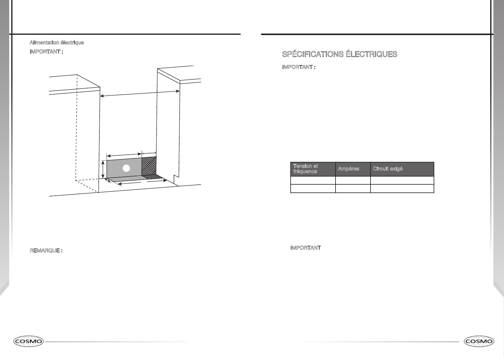
IMPORTANT : Une prise électrique au plancher peut être soit encastrée soit
montée en surface, mais une prise électrique murale doit être encastrée pour
pouvoir effectuer le raccordement. Pour un câblage direct, le boîtier de
raccordement doit être monté sur le mur.
a
b
e
d
g
h
c
f
a 30" (76 cm)
b 111/2" (29.2 cm)
c 6" (15.2 cm)
d 71/4" (18.4 cm)
e 3" (7.6 cm)
f 17
1
/
2
" (44 cm)
g Emplacement conseillé pour
la prise électrique
h Emplacement conseillé
pour le raccordement à
l’alimentation en gaz
R
EMARQUE : Distance de séparation minimale de 24" (61 cm) lorsque le fond
d’un placard de bois ou de métal est protégé par une planche ignifugée d’au
moins 1/4" (0,64 cm) recouverte d’une tôle d’acier d’épaisseur égale ou
supérieure au calibre 28 MSG, d’acier inoxydable de 0,015" (0,4 mm),
d’aluminium de 0,024" (0,6 mm), ou de cuivre de 0,020" (0,5 mm). Distance de
séparation minimale de 30" (76,2 cm) entre le dessus de la table de cuisson et le
fond d’un placard de bois ou de métal non protégé.
Exigences d'installation
37
SPÉCIFICATIONS ÉLECTRIQUES
IMPORTANT : Utiliser un cordon d’alimentation à 3 fils, homologué UL, un
cordon d’alimentation de 30 ampères (queue de cochon); ou si les codes
locaux ne permettent pas la mise à la terre à travers le fil neutre, utiliser un
cordon d’alimentation à 4 fils, homologué UL, 30 ampères spécifié pour
une tension nominale de 250 volts et approuvé pour une utilisation avec
des cuisinières.
Si les codes locaux le permettent et un fil de terre séparé est utilisé, il est
recommandé qu’un électricien qualifié vérifie que le chemin de terre est
adéquat et que le calibre du fil de terre est conforme aux codes locaux.
Afin d’installer correctement votre cuisinière, vous devez déterminer le type
de connexion électrique que vous allez utiliser et suivre les instructions
indiquées ici.
La cuisinière doit être connectée à la tension électrique et fréquence
spécifiées sur le modèle / numéro de série de la plaque signalétique. Tous
les modèles sont conçus pour être raccordés soit à monophasée de
120/240V ou 120/208V CA, 60 Hz, 3 fils ou soit à une alimentation, 4 fils.
Tension et
fréquence
Ampères Circuit exigé
240V, 60 Hz 20A
25 Amp Circuit
208V, 60 Hz 17.4A
20 Amp Circuit
Lorsqu’une source d’électricité monophasée de 120/240 volts, 60 Hz/4
conducteurs (CA uniquement) est disponible, le circuit doit comporter
un dispositif de protection de 25 A maximum (ou 20 A si la source
d’électricité spécifiée sur la plaque signalétique est de 120/208 volts).
Pour les installations de fils directs, installer une boîte de dérivation
appropriée (non fournie). Un connecteur de conduit homologué UL de taille
appropriée doit être utilisé pour fixer correctement le conduit à la boîte de
dérivation.
I
MPORTANT Les codes locaux peuvent varier; les raccordements
électriques d’installation et de mise à la terre doivent être conformes à tous
les codes locaux applicables.
Si les codes locaux permettent la mise à la terre à travers le neutre de
l’alimentation électrique, connecter le fil neutre blanc et le fil de terre vert de la
cuisinière au fil neutre blanc de l’alimentation électrique.
Exigences d'installation
38 39
  • Page 1 1
  • Page 2 2
  • Page 3 3
  • Page 4 4
  • Page 5 5
  • Page 6 6
  • Page 7 7
  • Page 8 8
  • Page 9 9
  • Page 10 10
  • Page 11 11
  • Page 12 12
  • Page 13 13
  • Page 14 14
  • Page 15 15
  • Page 16 16
  • Page 17 17
  • Page 18 18
  • Page 19 19
  • Page 20 20
  • Page 21 21
  • Page 22 22
  • Page 23 23
  • Page 24 24
  • Page 25 25
  • Page 26 26
  • Page 27 27
  • Page 28 28
  • Page 29 29
  • Page 30 30
  • Page 31 31
  • Page 32 32
  • Page 33 33

Cosmo COS-305DFSC Manuel utilisateur

Catégorie
Cuisinières
Taper
Manuel utilisateur

dans d''autres langues