SportsArt TR35 Le manuel du propriétaire
- Catégorie
- Tapis de course
- Taper
- Le manuel du propriétaire

TR35 OWNER’S MANUAL CONTENTS
1. INTRODUCTION ................................................................................ 2
2. SAFETY PRECAUTIONS .................................................................. 3
3. LIST OF PARTS ................................................................................. 5
4. ASSEMBLE THE PRODUCT ............................................................. 7
STEP 1 Inspect the Walk Belt Position .................................................. 7
STEP 2 Install the Pedestals ................................................................. 8
STEP 3 Install the Short Handrails ........................................................ 11
STEP 4 Install the Display ..................................................................... 12
STEP 5 Move the Treadmill into Place for Use ..................................... 13
STEP 6 Level the Treadmill ................................................................... 14
STEP 7 Align the Walk Belt ................................................................... 15
STEP 8 Adjust the Walk Belt Tension .................................................... 16
STEP 9 Install the Power Cord ............................................................... 17
STEP 10 Safety Key Installation and Use .............................................. 18
5. UNDERSTAND THE TR35 DISPLAY ................................................ 19
DISPLAY Overview ................................................................................ 19
DISPLAY Windows ................................................................................. 19
DISPLAY Keys ....................................................................................... 20
DISPLAY Safety Key ............................................................................ 22
6. OPERATE THE TR35 TREADMILL ................................................... 23
OPERATION Safety Operating Area ..................................................... 23
OPERATION Proper Workout Position and Safety Get Off ................... 24
OPERATION Quick Start ....................................................................... 25
OPERATION Start a Workout Program ................................................. 25
OPERATION Display .............................................................................. 26
OPERATION Cool Down ........................................................................ 26
OPERATION Workout Programs ........................................................... 27
OPERATION Basic Settings .................................................................. 29
7. ABOUT HEART RATE DETECTION .................................................. 30
HEART RATE Telemetry ........................................................................ 30
HEART RATE Contact ........................................................................... 30
8. GUIDELINES FOR EXERCISE ......................................................... 31
9. MAINTENANCE ................................................................................ 32
MAINTENANCE Safety Precautions .................................................... 32
MAINTENANCE Error Messages .......................................................... 33
MAINTENANCE Replacing the Fuse ..................................................... 34
MAINTENANCE Lubrication .................................................................. 35
MAINTENANCE Schedule ..................................................................... 40
MAINTENANCE Task List ...................................................................... 41
MAINTENANCE One-Year Maintenance Log ........................................ 42
10. ACCESSORIES ............................................................................. 43
ACCESSORIES Options ..................................................................... 43
11. CONSIGNES DE SÉCURITÉ IMPORTANTES ............................... 44
12. APPENDIXES ................................................................................ 46
APPENDIXES Specications ............................................................... 46
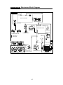
APPENDIXES Electronics Block Diagram ........................................... 47
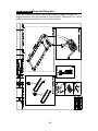
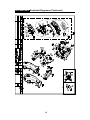
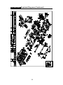
APPENDIXES Exploded Diagrams....................................................... 48
*We reserve the right to revise this manual at any time without notice.

2
1. INTRODUCTION
Congratulations on the purchase of a high quality SportsArt product, the TR35
treadmill. Constructed of high quality materials and designed for years of reliable
performance, this product was made for home use.
Before this product is assembled or operated, we recommend that you familiarize
yourself with this manual. Understanding the correct assembly and operation of
this product will help ensure that exercisers obtain their tness goals safely and
successfully.

3
2. SAFETY PRECAUTIONS
This product was designed and built for optimum safety. However certain precau-
tions apply during the use of this product. Please note the following safety
precautions:
• Please read the entire manual before assembly and operation. Make
sure the product is installed and operated as instructed in this manual.
• Assemble and operate the product on a solid, level surface. Do not use
outdoors or near water, including pools and saunas.
• Check the product before every use. Make sure all parts are assem-
bled, and all fasteners are tightened. Do not use the product if it is disas-
sembled in any way.
• Wear proper workout clothing. Do not wear loose clothing. Do not wear
shoes with leather soles or high heels. Tie all long hair back. Do not go
barefoot on this product.
• Keep away from moving parts. Moving parts may or may not stop imme-
diately if an object becomes caught or impedes normal motion.
• Use this product only for its intended purpose as described in this
manual.
• Be careful when mounting and dismounting the unit.
• Never operate this product if it has been damaged in any way. If it is
not working properly, or has been dropped or damaged, contact a service
technician for repairs.
• Do not use accessories or parts that are not specically recommended
by the manufacturer (SportsArt). Such parts might cause injuries or cause
the unit to fail and void the warranty. We will not be responsible for any
safety issue that arises due to the misuse of accessories or parts. At the
same time, we will terminate the warranty terms of this equipment.
• Keep all air ventilation areas free of blockage. Never drop or insert any
object into any opening.
• Do not operate where aerosol (spray) products are being used or where
oxygen is being administered.
• This product is not intended for use by persons (including children 12
or younger) with reduced physical, sensory, or mental capabilities, or by
people who are otherwise decient in product knowledge or experience. If
such people use this product, they should be given training and be super-
vised at all times by someone responsible for their safety.
• Contact your SportsArt representatives on all materials damaged in
shipment. (Note: Shipping damages are the responsibility of the carrier.)
• Unpack and verify contents of boxes according to the list of parts to check
if any parts are missing.
• Children 12 or younger should be supervised to ensure that they do not
play on or near the product.
• The user weight limit for this product is 205 kg, 450 lb. At maximum
speed, this product meets standards for users up to 135 kg, 298 lb.

4
2. SAFETY PRECAUTIONS (CONTINUED)
CAUTION: If you feel any pain or abnormal sensations, STOP YOUR WORK-
OUT and consult your physician immediately. Work within your recommend-
ed exercise level. DO NOT work to exhaustion. Before beginning any exercise
program, you should consult with your doctor. It is recommended that you undergo
a complete physical examination.
WARNING! Heart rate monitoring systems may be inaccurate. Over exercise may
result in serious injury or death. If you feel faint, stop exercising immediately.
Note: This equipment has been tested and found to comply with the limits for a Class
B digital device, pursuant to part 15 of the FCC Rules. These limits are designed to
provide reasonable protection against harmful interference in a residential instal-
lation. This equipment generates, uses and can radiate radio frequency energy and,
if not installed and used in accordance with the instructions, may cause harmful
interference to radio communications. However, there is no guarantee that inter-
ference will not occur in a particular installation. If the user desires to correct the
interference, it is at the user’s own expense.
WARNING! Only qualied technicians should be allowed to contact electrical
components such as circuit boards. Some components carry an electrical charge
even after use has been discontinued or the product has been unplugged. For
products with power cords, turn off unit power, wait ve minutes, then disconnect
the power cord from the power socket. For products without power cords, let the unit
sit without use for ve minutes. Only after taking such precautions should covers be
removed and electrical components be accessed.
• Do not attempt to drag or carry this unit by the power cord. Keep the
power cord away from heated surfaces.
• Improper grounding can increase the risk of electric shock. Check with
a qualied electrician if you are in doubt as to whether the power outlet is
properly grounded.
• Do not attempt to modify the plug provided with this product. Proper
power supply must be provided. If the plug does not t an outlet, contact a
qualied electrician to inspect or modify power in the facility.
• Do not stand on the walk belt when starting the treadmill. Straddle the
belt with your feet on the right and left landing strips.
• Always use the safety key when operating the treadmill.
• Close supervision is necessary when this treadmill is used by, on, or near
children 12 or younger, invalids, or disabled persons
• The treadmill should be disconnected from its power source during ser-
vice and when replacing parts.
• Maintenance and repair must be performed by trained service person-
nel only. Improper maintenance would not only damage the machine, but
may also present a danger to the exerciser.
• Warning that any of the adjustment devices that could interfere with the
user’s movement should not be left projecting.

5
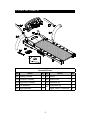
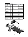
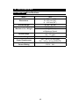
3. LIST OF PARTS
Assembly Parts
No. Name Qty. No. Name Qty.
A1 Display console 1 A4 Frame 1
A1a Left short handrail 1 A5 Power cord 1
A1b Right short handrail 1 A6 Hardware kit 1
A2 Left pedestal 1
A7
Lubrication kit 1
A3 Right pedestal 1 Hyper Glide™ Lubricant 4

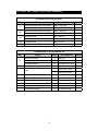
6
Components in the Hardware Kit
No. Name Qty. Specication Notes
31
Inner hex screw 4 M8*L50
Spring washer 4 M8*t2.0
Serrated washer 4 D18*d8.5*t2.0*19T
32 Safety key 1
Fuse
1 15A-100V~110V
1 10A-200V-240V
T-shaped Allen wrench 1 M4
T-shaped Allen wrench 1 M5
T-shaped Allen wrench 1 M6
L-shaped Allen wrench 1 M6
Screwdriver handle 1 Green
Screwdriver shank 1 Phillips and at
Components on the Product
No. Name Specication Notes
41
Mushroom top inner hex screw M8*P1.25*L20
Serrated washer D18*d8.5*t2.0*19T
42
Mushroom top inner hex screw M8*P1.25*L20
Serrated washer D18*d8.5*t2.0
43
Phillips screw M5*P0.8*L8
Cable clip
44 Phillips screw M4*P0.7*L8
45 Mushroom top Phillips screw M4*L16
3. LIST OF PARTS (CONTINUED)

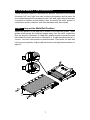
7
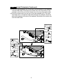
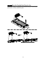
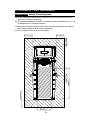
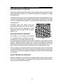
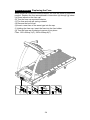
STEP 1 Inspect the Walk Belt Position
Inspect the position of the walk belt in relation to the walk belt guides. These
guides should press the walk belt edges away from the deck, toward the
floor, as shown in illustration O. Walk belt guides should not press the walk
belt toward the deck, as shown in illustration X. If walk belt placement is in-
correct, turn rear roller screws counterclockwise. Then place the walk belt
into the correct position. Adjust walk belt tension and alignment as shown on
page 12.
4. ASSEMBLE THE PRODUCT
Follow instructions below to assemble this product. Note that in this manual
the words “left” and “right” are used to refer to the product and its parts. As
such, these designations correspond to the “left” and “right” sides of a person
in position to exercise on this product. Also, for brevity, the word “screws” is
used where screws, washers, and other hardware may be involved.
A

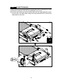
8
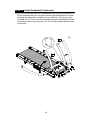
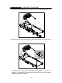
STEP 2 Install Pedestals
Please install left and right pedestals by following instructions (a) through (e) in order.
(a) Remove screws (41, 42) from the pedestal mount area.
(b) Cut the zip tie that secures the data cable onto the right pedestal mount.
Pull the top of the data cable away from the pedestal mount, and set the
data cable on the floor.
(b)
(a)

9
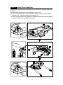
STEP 2 Install Pedestals (Continued)
(c) Place the right pedestal (A3) on the floor, with the bottom of the pedestal
near the data cable. Disconnect the feeder wire from the bottom of the
pedestal, and tie this end of the feeder wire to the top of the data cable.
(d) Untie the feeder wire from the top of the right pedestal (A3). Then pull
the feeder wire to thread the data cable through the pedestal. Once the
data cable appears at the top of the pedestal, disconnect the feeder wire
from the data cable.
(d)
(c)

10
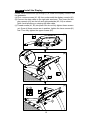
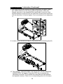
STEP 2 Install Pedestals (Continued)
(e) Once the data cable has been threaded through the right pedestal (A3),
lift the pedestal and set it into place on the right pedestal mount. Avoid
pinching the data cable. Loosely secure screws (41, 42) into the right
pedestal mount. Then insert the left pedestal into the left pedestal mount,
and loosely secure its screws (41, 42). Do not fully tighten these screws
at this time.
(e)

11
STEP 3 Install Short Handrails
Please follow instructions (a) through (c) to install the left and right short
handrails.
(a) Disconnect wires (43) from the display console (A1).
(b) Insert left and right short handrails (A1a, A1b) into place on the display
console (A1), and secure them with screws (31).
(c) After securing the left and right short handrails (A1a, A1b) onto the display
console, insert wires (43) back into place.
(c)
(b)
(a)

12
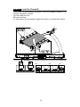
STEP 4 Install the Display
Please follow instructions (a) through (c) to install the display console onto
the pedestals.
(a) First, remove screws (41, 42) from underneath the display console (A1).
(b) Connect the data cable on the right side as shown. Then insert the dis
play console (A1) into the left and right pedestals (A2, A3) as shown.
Note: Avoid pinching or crimping the data cable.
(c) Thread screws (41, 42) into place. But do not fully tighten these screws
yet. Once all these screws are in position, tighten the lower screws (41)
first. Then fully tighten the upper screws (42).
(c)
(b)
(a)

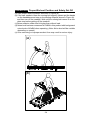
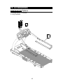
13
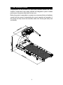
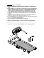
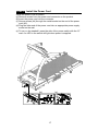
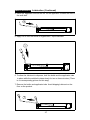
STEP 5 Move the Treadmill into Place for Use
Grip the bar in area A. Lift the back of the treadmill and push. Use the trans-
port wheels to roll the treadmill into place.
A

14
STEP 6 Level the Treadmill
Press down on the treadmill as shown. Does the treadmill wobble? If so,
level the treadmill as follows:
(a) First loosen the nut.
(b) Lower the foot.
(c) Then secure the nut upward, against the frame, to secure this position.
(a) (b) (c)

15
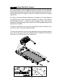
STEP 7 Align the Walk Belt
(a) First, make sure the treadmill is on a level surface and the incline is at
0%.
(b) Start the speed at a lower rate of 3kph/2.5mph to check if the walk belt is
aligned and if there is an equal amount of space between walk belt and
side-rails on both sides at the front end of the treadmill. Turn the rear
roller adjustment screw to adjust the walk belt if there is misalignment.
(c) Adjust the speed higher to 15kph/10mph or above to ensure the belt is
aligned.
(d) Adjust the edge of walk belt and make sure there should be an equal
amount of space on both sides of the walk belt (A = B).
(e) Let the treadmill run for 2 minutes or more to see if the walk belt move. If
so or (A ≠ B), repeat the procedure (d).
(f) Finish adjustment and the walk belt will be aligned.
*Make adjustments as needed, but avoid turning rear roller screws more
than one quarter rotation at a time.
*The belt alignment should be judged by the front end of the treadmill, not
the rear end. If there is a little misalignment at the rear end, it is fine to
continue using it because that will not affect the treadmill performance.

16
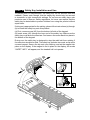
STEP 8 Adjust Walk Belt Tension
When the exerciser’s foot touches the walk belt normally, does the walk belt
slip, pausing briefly? If so, the walk belt may be too loose. Or, if the exerciser
bears down hard against the walk belt, does the walk belt not slip at all? If so,
the walk belt may be too tight. In either case, walk belt tension may require
adjustment.
One way to determine whether adjustment is needed is to lift both edges of
the walk belt at the center of the belt lengthwise. The sides of the walk belt
should lift about 30 mm, 1 1/8ths inch, or to a weight of 3 kg, 6.6 lb. This is
standard for walk belt tension. Any variance from this standard indicates that
adjustment is needed.
To tighten the walk belt, turn rear roller adjustment screws clockwise up to
1/4 turn at a time. Then test walk belt tension.
To loosen the walk belt, turn rear roller adjustment screws counterclockwise
up to 1/2 turn at a time. Then test walk belt tension. Repeat these steps as
necessary until walk belt tension is appropriate.
(b)
(a)

17
STEP 9 Install the Power Cord
Install the power cord as follows:
(a) Remove screws from the power cord connector on the product.
(b) Insert the power cord into the connector.
(c) Secure screws (44) through the metal bracket on the end of the power
cord (A5).
(d) Plug the other end of the power cord into an appropriate power supply
socket on the wall.
(e) To turn on the treadmill, press the side of the power switch with the “O”
mark. An LED in the switch will light when power is supplied.
(c)(b)
(a)

18
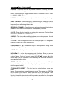
STEP 10 Safety Key Installation and Use
To prevent theft or misplacement, the safety key can be secured onto this
treadmill. Please note, though, that the safety key should only be secured
to treadmills in light commercial settings. Do not secure safety keys onto
products used in homes. Safety regulations for home use require that the
safety key be detachable to prevent children from using the product without
supervision.
If doing so is appropriate for the setting, please follow instructions (a) through
(b) to install the safety key onto this product.
(a) First, remove screw (45) from the bottom left side of the keypad.
(b) Insert screw (45) through the loop end of the safety key. Make sure the
safety key cord faces the exerciser. And secure the screw back into place in
the bottom of the keypad.
During use, the safety key is designed to stop the walk belt from rotating if
the exerciser stumbles or falls. The safety key includes two ends: a clip and a
covered magnet. Secure the clip onto your clothing, and set the magnet into
place on the display. If the magnet is not in place on the display, the words
“SAFETY KEY” will appear, and the treadmill will not operate.
(b)
(a)
L
R

19
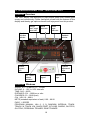
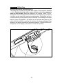
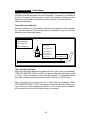
5. UNDERSTAND THE TR35 DISPLAY
DISPLAY Overview
The TR35 display was designed to help people obtain their fitness goals
simply and conveniently. Please familiarize yourself with the features of this
display and thereby get optimum benefit and enjoyment from this product.
Actual
heart rate
Cardio
target
heart rate
Exercise
feedback
window
Weight
loss target
heart rate
Muscle
activation
indicator
Cushion
adjustment
keys
Workout
program
keys
Dot matrix/
workout
illustration
Numeric
keys
Lower
keypad
DISPLAY Windows
SPEED: 0.2 – 20 kph or 0.1 – 12 mph
INCLINE: 0 – 15%, in 0.5% intervals
TIME: 0:00 – 99:59
DISTANCE: 0.01 – 9999 km or mile
CALORIES: 0.0 – 9999 (kcal)
CAL / HR: 0.0 – 999.9
METS (metabolic equivalent of task): 0.00 – 99.00
PACE: 1 / SPEED
PROGRAM: MANUAL, HILL (1, 2, 3), RANDOM, INTERVAL, TRACK,
TRACK 5 K, TRACK 10 K, QUICK START, WT LOSS, CARDIO, GLUTE 30,
GLUTE 45, PERSONAL TRAINER, ZONE TRAINER

20
DISPLAY Windows (Continued)
The dot matrix/workout illustration window shows workout illustrations
and prompts.
The exercise feedback window shows exercise information. Press the
CHANGE DISPLAY key to toggle between upper and lower rows of workout
information.
The CardioAdvisor™ system features actual heart rate (center) and opti-
mum target heart rates for weight loss (left) and cardio conditioning (right).
In these heart rate control programs, 65% (weight loss) and 80% (cardio
conditioning) target heart rates are automatically calculated based on user
age. Actual heart rate values appear in the center window.
DISPLAY Keys
Basic key functions are introduced briefly below. Program functions are dis-
cussed in more detail in the following section.
QUICK START – Press this key to start exercising without first entering user
information including age and weight. Time will automatically count upward.
START – Press this key to start exercising after first entering user informa-
tion including age and weight.
ENTER – After making a selection, press this key to confirm your choice.
CHANGE DISPLAY – This key controls the exercise feedback screen, which
shows workout status in two rows. Only one row of feedback is activated at
a time. Top row: calories, speed, time, distance. Bottom row: calories per
hour, metabolic equivalent of task, pace, incline. When the SCAN LED is lit,
views of exercise feedback alternate, showing one row for a time, followed
by the other row.
Firm - Press this key to make the deck “harder.” The number of lit CUSHION
LEDs will increase until all five LEDs are lit. Level five provides the firmest
surface.
Soft – Press this key to make the deck “softer.” The number of lit CUSHION
LEDs will decrease until only one LED is lit. Level one provides the most
cushioning.
TRACK – Each time the TRACK key is pressed, one of three different track
programs will appear: TRACK→ TRACK 5 K→ TRACK 10 K→ TRACK→….
INTERVAL – Press this key to establish a workout with rest and work seg-
ments that vary in intensity.
La page est en cours de chargement...
La page est en cours de chargement...
La page est en cours de chargement...
La page est en cours de chargement...
La page est en cours de chargement...
La page est en cours de chargement...
La page est en cours de chargement...
La page est en cours de chargement...
La page est en cours de chargement...
La page est en cours de chargement...
La page est en cours de chargement...
La page est en cours de chargement...
La page est en cours de chargement...
La page est en cours de chargement...
La page est en cours de chargement...
La page est en cours de chargement...
La page est en cours de chargement...
La page est en cours de chargement...
La page est en cours de chargement...
La page est en cours de chargement...
La page est en cours de chargement...
La page est en cours de chargement...
La page est en cours de chargement...
La page est en cours de chargement...
La page est en cours de chargement...
La page est en cours de chargement...
La page est en cours de chargement...
La page est en cours de chargement...
La page est en cours de chargement...
La page est en cours de chargement...
La page est en cours de chargement...
-
 1
1
-
 2
2
-
 3
3
-
 4
4
-
 5
5
-
 6
6
-
 7
7
-
 8
8
-
 9
9
-
 10
10
-
 11
11
-
 12
12
-
 13
13
-
 14
14
-
 15
15
-
 16
16
-
 17
17
-
 18
18
-
 19
19
-
 20
20
-
 21
21
-
 22
22
-
 23
23
-
 24
24
-
 25
25
-
 26
26
-
 27
27
-
 28
28
-
 29
29
-
 30
30
-
 31
31
-
 32
32
-
 33
33
-
 34
34
-
 35
35
-
 36
36
-
 37
37
-
 38
38
-
 39
39
-
 40
40
-
 41
41
-
 42
42
-
 43
43
-
 44
44
-
 45
45
-
 46
46
-
 47
47
-
 48
48
-
 49
49
-
 50
50
-
 51
51


SportsArt TR35 Le manuel du propriétaire
- Catégorie
- Tapis de course
- Taper
- Le manuel du propriétaire
dans d''autres langues
- English: SportsArt TR35 Owner's manual
Documents connexes
-
SportsArt TR9800 Le manuel du propriétaire
-
-
-
-
-
-
-
-
-