GE Profile UVW7301SWSS Le manuel du propriétaire
- Catégorie
- Hottes
- Taper
- Le manuel du propriétaire
Ce manuel convient également à

Write the model and serial
numbers here:
Model # _________________
Serial # _________________
You can find them on a label on
the inside of the hood.
49-7000197 Rev. 0 03-23 GEA
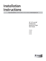
UVW7301
UVW7361
OWNER’S MANUAL &
INSTALLATION
INSTRUCTIONS
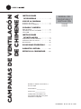
CHIMNEY
VENT HOODS
SAFETY INFORMATION ............ 3
USING THE HOOD
Light Controls ........................... 5
Vent Controls ........................... 5
CARE AND CLEANING
Grease Filter ............................ 6
Stainless Steel Surfaces ................... 7
LED Lights .............................. 7
INSTALLATION INSTRUCTIONS .. 8
Installation Preparation ................... 9
Vented to the Outside ....................14
Recirculating ............................18
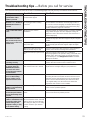
TROUBLESHOOTING TIPS ........ 23
LIMITED WARRANTY ............. 25
CONSUMER SUPPORT ............26
ESPAÑOL
For a Spanish version of this
manual, visit our Website at
GEAppliances.com.
Para consultar una version
en español de este manual
de instrucciones, visite nuestro
sitio de internet
GEAppliances.com.
FRANÇAIS
For a French version of this
manual, visit our Website at
GEAppliances.ca.
Pour un version français de
ce manuel d’utilisation, veuillez
visiter notre site web à l’adresse
GEAppliances.ca.

249-7000197 Rev. 0
THANK YOU FOR MAKING GE APPLIANCES A PART OF YOUR HOME.
Whether you grew up with GE Appliances, or this is your first, we’re happy to have you in the family.
We take pride in the craftsmanship, innovation and design that goes into every GE Appliances
product, and we think you will too. Among other things, registration of your appliance ensures that we
can deliver important product information and warranty details when you need them.
Register your GE appliance now online. Helpful websites and phone numbers are available in the
Consumer Support section of this Owner’s Manual. You may also mail in the pre-printed registration
card included in the packing material.

49-7000197 Rev. 0 3
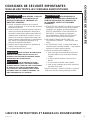
SAFETY INFORMATION
READ AND SAVE THESE INSTRUCTIONS
IMPORTANT SAFETY INFORMATION
READ ALL INSTRUCTIONS BEFORE USING THE APPLIANCE
WARNING TO REDUCE THE RISK OF FIRE,
ELECTRIC SHOCK OR INJURY TO PERSONS,
OBSERVE THE FOLLOWING:
A. Use this unit only in the manner intended by the
manufacturer. If you have questions, contact the
manufacturer.
B. Before servicing or cleaning unit, switch power off
at service panel and lock the service disconnecting
means to prevent power from being switched on
accidentally. When the service disconnecting means
cannot be locked, securely fasten a prominent
warning device, such as a tag, to the service panel.
C. Do not use this unit with any solid-state speed
control device.
D. This unit must be grounded.
CAUTION For general ventilating use only. Do
not use to exhaust hazardous or explosive materials
and vapors.
CAUTION To reduce risk of fire and to properly
exhaust air, be sure to duct air outside. Do not vent
exhaust air into spaces within walls or ceilings or into
attics, crawl spaces or garages.
WARNING TO REDUCE THE RISK OF INJURY
TO PERSONS IN THE EVENT OF A RANGE TOP
GREASE FIRE, OBSERVE THE FOLLOWING*:
A. SMOTHER FLAMES with a close-fitting lid, cookie
sheet or metal tray, then turn off the burner. BE
CAREFUL TO PREVENT BURNS. If the flames
do not go out immediately, EVACUATE AND CALL
THE FIRE DEPARTMENT.
B. NEVER PICK UP A FLAMING PAN— You may be
burned.
C. DO NOT USE WATER, including wet dishcloths or
towels - a violent steam explosion will result.
D. Use an extinguisher ONLY if:
1. You know you have a Class ABC extinguisher,
and you already know how to operate it.
2. The fire is small and contained in the area where
it started.
3. The fire department is being called.
4. You can fight the fire with your back to an exit.
* Based on “Kitchen Fire Safety Tips” published by
NFPA.

449-7000197 Rev. 0
SAFETY INFORMATION
READ AND SAVE THESE INSTRUCTIONS
IMPORTANT SAFETY INFORMATION
READ ALL INSTRUCTIONS BEFORE USING THE APPLIANCE
WARNING TO REDUCE THE RISK OF A
RANGE TOP GREASE FIRE:
A. Never leave surface units unattended at high
settings. Boilovers cause smoking and greasy
spillovers that may ignite. Heat oils slowly on low or
medium settings.
B. Always turn hood ON when cooking on high heat or
when flambéing food (i.e. Crepes Suzette, Cherries
Jubilee, Peppercorn Beef Flambé).
C. Clean ventilating fans frequently. Grease should not
be allowed to accumulate on fan or filter.
D. Use proper pan size. Always use cookware
appropriate for the size of the surface element.
WARNING TO REDUCE THE RISK OF FIRE,
ELECTRIC SHOCK OR INJURY TO PERSONS,
OBSERVE THE FOLLOWING:
A. Installation work and electrical wiring must be
done by qualified person(s) in accordance with all
applicable codes and standards, including fire-rated
construction.
B. Sufficient air is needed for proper combustion and
exhausting of gases through the flue (chimney) of
fuel burning equipment to prevent back drafting.
Follow the heating equipment manufacturer’s
guidelines and safety standards, such as
those published by the National Fire Protection
Association (NFPA), the American Society for
Heating, Refrigeration and Air Conditioning
Engineers (ASHRAE) and the local code authorities.
When applicable, install any makeup (replacement)
air system in accordance with local building
code requirements. Visit GEAppliances.com for
available makeup air solutions.
C. When cutting or drilling into wall or ceiling, do not
damage electrical wiring and other hidden utilities.
D. Ducted fans must always be vented to the outdoors.
F. Turn off breaker to adjacent rooms while working.
WARNING TO REDUCE THE RISK OF FIRE,
USE ONLY METAL DUCTWORK.
Ŷ Do not attempt to repair or replace any part of your
hood unless it is specifically recommended in this
manual. All other servicing should be referred to a
qualified technician.

49-7000197 Rev. 0 5
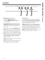
Controls
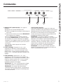
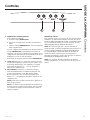
USING THE HOOD: Controls
3 2 1
1. MEMORY/OFF: To set the memory:
A. Press the MEMORY/OFF button.
B. Set your desired fan and light settings.
C. Press the MEMORY/OFF button again to save
these settings.
With your desired settings in memory, press the
MEMORY/OFF button to restore the fan and light
levels to their saved settings. These settings will
remain in memory until they are changed or loss of
power occurs.
To turn off the hood, press the MEMORY/OFF button.
2. LIGHT: Press + or – to increase or decrease light
level to desired setting. There are 2 light levels (LOW,
HIGH) and OFF. If you continue to press the + or –
buttons, the light will cycle back through the settings.
3. FAN. Press + or – to increase or decrease fan level
to your desired setting. There are 4 fan levels (LOW,
MED, HIGH, BOOST) and OFF. If you continue to
press the + or – buttons, the fan will cycle back
through the settings.
NOTE: There is an audible “beep” each time a button
is pressed. This is normal.
NOTE: The collars around the buttons will illuminate
when pressed. This is normal. The collars will
automatically turn off if the hood is turned off.
HEAT SENSOR:
This hood is equipped with a heat sensor that will turn
on the fan if excessive temperatures are detected (over
Û&Û)DERYHWKHFRRNLQJVXUIDFH7KHKRRGZLOO
return to its normal operation once the heat sensor
GHWHFWVWHPSHUDWXUHVEHORZÛ&Û)
NOTE: If the hood is OFF or on LOW fan speed, the
WHPSHUDWXUHVDERYHÛ&Û)DUHGHWHFWHGWKHQWKH
fan will automatically adjust to MED speed. You may
adjust the fan speed to HIGH or BOOST, but you will
not be able to adjust the fan speed to LOW or OFF until
WHPSHUDWXUHVEHORZÛ&Û)DUHGHWHFWHG
NOTE: The collars around the buttons may not illuminate
if the heat sensor is activated. This is normal.

649-7000197 Rev. 0
Filters
CARE AND CLEANING: Filters
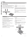
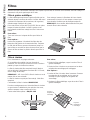
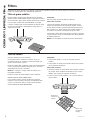
Metal Grease Filter
The metal filter traps grease released by foods from the
cooktop. The filter also helps prevent flames (from food,
grease) from damaging the inside of the hood.
For this reason, the filter must ALWAYS be in place when
the hood is in use. The grease filter is dishwasher-safe
and should be cleaned every 6 months, or as needed.
To remove:
Pull downward on the filter lock to release the filter.
To replace:
Fit the tabs at the end of the filter into the slots in left
side of the filter opening. Lift up the right side of the filter
and push gently until the filter locks into place. Make
sure the filter lock is in the closed position to secure the
filter.
To clean, swish the filter in hot soapy water and rinse
in clean water or wash it in the dishwasher. Do not use
abrasive cleansers.
NOTE: Some discoloration will occur in the dishwasher.
Charcoal Filter
For recirculating installation only
If the model is not vented to the outside, the air will be
recirculated through a disposable charcoal filter that
helps remove smoke and odors.
The charcoal filter should be replaced when it is
noticeably dirty or discolored (usually after 6 to 12
months, depending on hood usage).
NOTE: DO NOT rinse, or put charcoal filter in an
automatic dishwasher.
The charcoal filter cannot be cleaned. It must be
replaced.
2UGHU&KDUFRDO)LOWHU:%;
To inquire about purchasing replacement charcoal filters
or to find the location of a dealer nearest you, please call
our toll-free number:
1DWLRQDO3DUWV&HQWHU
To remove:
1. Remove the metal filter—see Metal grease filter
section.
2. Remove the charcoal filter by pushing in on both
locking tab handles to release.
To replace:
1. Insert the charcoal filter into the opening. Push the
locking tab handles toward the center and release to
engage the locking tabs.
2. Replace the metal filter—see Metal grease filter
section.
Be sure electrical power is off and all surfaces are cool before cleaning or servicing any part of the vent hood.
Locking tab handle
Locking tab handle

49-7000197 Rev. 0 7
Care and Cleaning
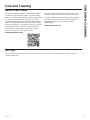
Stainless Steel Surfaces
'RQRWXVHDVWHHOZRROSDGLWZLOOVFUDWFKWKHVXUIDFH
To clean the stainless steel surface, use warm sudsy
water or a stainless steel cleaner or polish. Always wipe
the surface in the direction of the brush line. Follow
the cleaner instructions for cleaning the stainless steel
surface. Cleaners with oxalic acid such as Bar Keepers
Friend Soft Cleanser™ will remove surface rust, tarnish,
and small blemishes. To receive a $2.00 coupon for
a trial sample of Bar Keepers Friend Soft Cleanser™
follow the link below or scan the QR Code.
barkeepersfriend.com/ge
Use only a liquid cleanser free of grit and rub in the
direction of the brush lines with a damp soft sponge.
To inquire about purchasing stainless steel appliance
cleaner or polish, or to find the location of a dealer
nearest you, please call our toll-free number:
GEApplianceParts.com
CARE AND CLEANING
LED Lights
The LED lights are replaceable by a service technician only. See the Limited Warranty section for service
contact information.

49-7000197 Rev. 0
Installation
Instructions
If you have questions, call GE Appliances at 800.GE.CARES (800.432.2737)
or visit our website at: GEAppliances.com
BEFORE YOU BEGIN
Read these instructions completely and carefully.
Ŷ IMPORTANT – Save these instructions
for local inspector’s use.
Ŷ IMPORTANT – Observe all governing
codes and ordinances.
Ŷ Note to Installer – Be sure to leave these
instructions with the Consumer.
Ŷ Note to Consumer – Keep these instructions for
future reference.
Ŷ Skill level – Installation of this vent hood requires
basic mechanical and electrical skills.
Ŷ Completion time – Approximately 1 to 3 hours
Ŷ Proper installation is the responsibility of the
installer.
Ŷ Product failure due to improper installation is not
covered under the Limited Warranty.
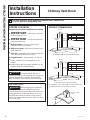
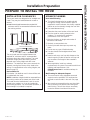
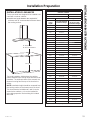
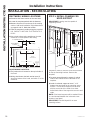
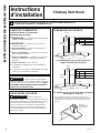
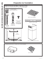
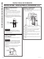
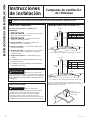
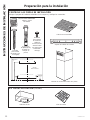
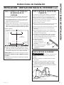
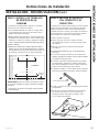
PRODUCT DIMENSIONS
Chimney Vent Hood
INSTALLATION INSTRUCTIONS
CAUTION Due to the weight and size of
these vent hoods and to reduce the risk of personal
injury or damage to the product, TWO PEOPLE
ARE REQUIRED FOR PROPER INSTALLATION.
FOR YOUR SAFETY:
WARNING Before beginning the installation,
switch power off at service panel and lock the
service disconnecting means to prevent power from
being switched on accidentally. When the service
disconnecting means cannot be locked, securely
fasten a prominent warning device, such as a tag, to
the service panel.
30” Models Require a 30” Wide Opening
”
*Height to
ceiling
”29´
10-7´
13-1´
2-”
*Height to Ceiling
Vented Recirculating
Min ´ ´
Max ´ ´
´ ´
´
´
36” Models Require a 36” Wide Opening
* For supplied duct cover ceiling heights for vented installation and
recirculating installation, refer to the table on page 13.
´
Allow 1” overlap
of duct.
´
*Height to Ceiling
Vented Recirculating
Min ´ ´
Max ´ ´
´
*Height to
Ceiling

49-7000197 Rev. 0 9
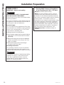
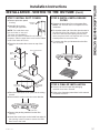
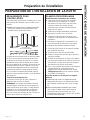
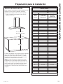
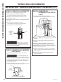
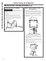
INSTALLATION CLEARANCES
These vent hoods are designed to be installed onto
a wall. They may be installed beneath a soffit or
cabinet.
Ŷ,QVWDOOWKHVHKRRGVEHWZHHQWKHUHTXLUHG´
minimum and 36” recommended maximum above
the cooking surface.
The vent hood must be installed between the
required 24” minimum and 36” recommended
maximum above the cooking surface. The hood
installation height above the cooking surface
depends upon ceiling height and duct cover
limitations. The telescopic duct cover conceals the
ductwork running from the top of the hood to the
ceiling. For supplied duct cover ceiling heights, see
table on page 13.
Recirculation Kit:
Kit includes 1 air deflector and 1 charcoal filter and
is included with the hood.
NOTE: Installation height should be measured from
the cooking surface to the lowest part of the hood.
This hood must be installed onto a wall. It can be
vented to the outdoors, or it can be installed for
recirculating operation. For recirculation operation, a
Recirculating Kit (included) is required.
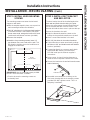
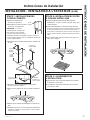
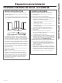
INSTALLATION INSTRUCTIONS
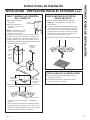
Installation Preparation
PREPARE TO INSTALL THE HOOD
ADVANCE PLANNING
Duct Install Planning
Ŷ This hood is designed to be vented vertically
through the ceiling. A duct transition piece is
supplied for vertical exhaust. Use locally supplied
elbows to vent horizontally through the rear wall.
Ŷ Use metal ductwork only.
Ŷ Determine the exact location of the vent hood.
Ŷ Plan the route for venting exhaust to the
outdoors. To maximize the ventilation
performance of the vent system:
1. Minimize the duct run length and number of
transitions and elbows.
2. Maintain a constant duct size.
3. Seal all joints with duct tape to prevent any
leaks.
4. Do not use any type of flexible ducting.
Ŷ Use the shortest and straightest duct route
possible.
Ŷ Install a wall cap or roof cap with damper at the
exterior opening. Order the wall or roof cap and
any transitions and length of duct needed in
advance.
Ŷ When applicable, install any makeup
(replacement) air system in accordance with local
building code requirements. Visit
GEAppliances.com for available makeup air
solutions.
Wall Framing for Adequate Support
Ŷ This vent hood is heavy. Adequate structural
support must be provided. The hood must be
secured to vertical studs in the wall. See page
14.
Ŷ We strongly recommend that the vent hood with
duct cover be on site before final framing and
wall finishing. This will also help to accurately
locate the ductwork and electrical service.
24” Required Min.
36” Recommended Max.

10 49-7000197 Rev. 0
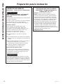
Installation Preparation
INSTALLATION INSTRUCTIONS
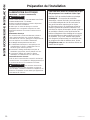
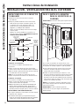
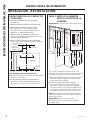
POWER SUPPLY
IMPORTANT—(Please read carefully)
WARNING
FOR PERSONAL SAFETY, THIS APPLIANCE
MUST BE PROPERLY GROUNDED.
Remove house fuse or open circuit breaker before
beginning installation.
Do not use an extension cord or adapter plug with
this appliance. Follow National Electrical Codes or
prevailing local codes and ordinances.
Electrical Supply
This vent hood must be supplied with 120V, 60Hz,
and connected to an individual, properly grounded
branch circuit, and protected by a 15 or 20 amp
circuit breaker or time delay fuse.
Ŷ:LULQJPXVWEHZLUHZLWKJURXQG
Ŷ,IWKHHOHFWULFDOVXSSO\GRHVQRWPHHWWKHDERYH
requirements, call a licensed electrician before
proceeding.
Ŷ5RXWHKRXVHZLULQJDVFORVHWRWKHLQVWDOODWLRQ
location as possible in the ceiling or wall. See
page 14 for details.
Ŷ&RQQHFWWKHZLULQJWRWKHKRXVHZLULQJLQ
accordance with local codes.
Grounding Instructions
The grounding conductor must be connected to
a ground metal, permanent wiring system, or an
equipment-grounding terminal or lead on the hood.
WARNING
The improper connection of equipment-grounding
conductor can result in a risk of electric shock.
Check with a qualified electrician or service
representative if you are in doubt whether the
appliance is properly grounded.
This Hood MUST Use an 8” Round Duct.
It Can Transition to a 3-1/4” x 12” Duct.
DO NOT use flexible plastic ducting.
NOTE: Any home ventilation system, such as a
ventilation hood, may interrupt the proper flow of
combustion air and exhaust required by fireplaces,
gas furnaces, gas water heaters and other naturally
vented systems. To minimize the chance of
interruption of such naturally vented systems, follow
the heating equipment manufacturer’s guidelines
and safety standards such as those published by
NFPA and ASHRAE. When applicable, install any
makeup (replacement) air system in accordance
with local building code requirements. Visit
GEAppliances.com for available makeup air
solutions.

49-7000197 Rev. 0 11
Installation Preparation
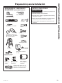
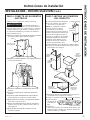
REMOVE THE PACKAGING
CAUTION Wear gloves to protect against
sharp edges.
Ŷ5HPRYHWKHGXFWFRYHUV
Ŷ5HPRYHWKHKDUGZDUHEDJOLWHUDWXUHSDFNDJHDQG
other boxed parts.
Ŷ5HPRYHDQGSURSHUO\GLVFDUGWKHSURWHFWLYH
plastic wrapping and other packaging materials.
Ŷ5HPRYHSDFNLQJIRDPIURPEHKLQGWKHEORZHU
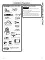
TOOLS AND MATERIALS REQUIRED
(NOT SUPPLIED)
Pliers
:LUHFXWWHUVWULSSHU
Metal snips
Spirit level
Aluminized
Duct tape
Safety glasses
120V 60Hz. 15 or 20 Amp,
2-wire with ground, properly
grounded branch circuit
Step ladder
Saber saw or Key Hole saw
Phillips screwdriver
Strain relief for
junction box
´5RXQGPHWDO
duct, length to
suit installation
Hammer
(OHFWULFGULOOZLWK´
bits, #2 Phillips head
Flashlight
UL listed wire nuts
Pencil and tape measure
INSTALLATION INSTRUCTIONS

12 49-7000197 Rev. 0
Installation Preparation
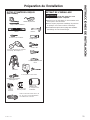
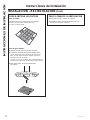
CHECK INSTALLATION HARDWARE
Locate the hardware package packed with the hood and check contents.
RECIRCULATING KIT (Included)
Air deflector Charcoal filter
Template
Stainless steel filter
INSTALLATION INSTRUCTIONS
REAR WALL
MOUNTING TEMPLATE
Vertical Centerline
ALIGN BOTTOM EDGE
WITH PENCIL LINE
INDICATING BOTTOM
OF THE HOOD
11-7/16"
Installation Height
Horizontal Line
C
L
DRILL 2 (TWO) 3/16" PILOT HOLES THROUGH STUDS OR REAR WALL SUPPORT
10-1/8"
12-08 JR
2"
DRILL 2 (TWO) 3/16" PILOT HOLES THROUGH STUDS OR REAR WALL SUPPORT
12-1/2"
WALL VENT IS 27-3/4" MIN.
ABOVE THE INSTALLATION
HEIGHT
31-14772 Printed in Mexico
HARDWARE PACKAGE
Locate and count screws
6 wood screws
´ORQJ
4 wall fasteners
´VFUHZ
with wall
anchor)
GXFWFRYHUDQG
air deflector screws
WKUHDGIRUPLQJ
VFUHZ´ORQJ Duct cover bracket
2-piece decorative duct cover

49-7000197 Rev. 0 13
INSTALLATION INSTRUCTIONS
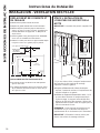
Installation Preparation
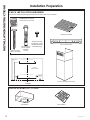
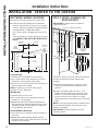
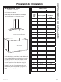
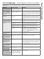
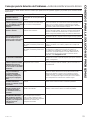
INSTALLATION CLEARANCES
These vent hoods are designed to be installed onto
a wall with no above cabinets.
Ŷ,QVWDOOWKHVHKRRGVEHWZHHQWKHUHTXLUHG´
minimum and 36” recommended maximum above
the cooking surface.
The hood installation height above the cooking
surface depends upon ceiling height and duct cover
limitations. The telescopic duct cover conceals the
ductwork running from the top of the hood to the
ceiling.
NOTE: Installation height should be measured from
the cooking surface to the lowest part of the hood.
This hood must be installed onto a wall. It can be
vented to the outdoors, or it can be installed for
recirculating operation. Recirculating Kit included
with hood.
24” Required Min.
36” Recommended Max.
36” Typical
UVW7301, UVW7361
Upper Duct Cover
Lower Duct Cover 27.56
Counter to Hood Height
Actual
Ceiling
Height
*Possible VENTED
Installation Height
*Possible
RECIRCULATING
Installation Height
7' 6" 24"
7' 7" 24" to 25"
24" to 26"
7' 9" 24" to 27"
7' 10" WR 24"
7' 11" 24" to 29" 24" to 25"
24" to 30" 24" to 26"
24" to 31" 24" to 27"
24" to 32" WR
24" to 33" 24" to 29"
24" to 34" 24" to 30"
24" to 35" 24" to 31"
24" to 36" 24" to 32"
24" to 36" 24" to 33"
24" to 36" 24" to 34"
24" to 36" 24" to 35"
24" to 36" 24" to 36"
24" to 36" 24" to 36"
9' 0" 24" to 36" 24" to 36"
9' 1" 24" to 36" 24" to 36"
9' 2" 24" to 36" 24" to 36"
9' 3" 25" to 36" 24" to 36"
9' 4" 26" to 36" 24" to 36"
9' 5" 27" to 36" 24" to 36"
9' 6" WR 24" to 36"
9' 7" 29" to 36" 25" to 36"
30" to 36" 26" to 36"
9' 9" 31" to 36" 27" to 36"
9' 10" 32" to 36" WR
9' 11" 33" to 36" 29" to 36"
10' 0" 34" to 36" 30" to 36"
10' 1" 35" to 36" 31" to 36"
10' 2" 36" 32" to 36"
10' 3" 33" to 36"
10' 4" 34" to 36"
10' 5" 35" to 36"
10' 6" 36"
* based on 36” countertop height

14 49-7000197 Rev. 0
Installation Instructions
INSTALLATION INSTRUCTIONS
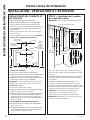
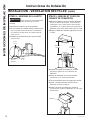
INSTALLATION - VENTED TO THE OUTSIDE
DUCTWORK, WIRING LOCATIONS
Ŷ Determine the exact location of the vent hood.
Ŷ Locate the template packed with the literature.
- Measure from the floor to the top of the cooking
surface. Add hood installation height determined
RQSDJHVDQG0DUNWKDWORFDWLRQ
- Use a level to draw a straight pencil line on the
wall.
- Tape the template in position along the penciled
line. CHECK TO BE SURE THE TEMPLATE IS
LEVEL.
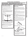
Ceiling ducting:
If ductwork will vent straight up to the ceiling:
Ŷ Use a level to draw a line straight up, from the
centerline on the template to the ceiling.
Ŷ Measure 5” from the back wall to the centerline of
DQ´KROHRQWKHFHLOLQJ
NOTE: If drywall is not present, add drywall
thickness to the 5” dimension.
Wall Ducting:
If ductwork will vent to the rear:
Ŷ Use a level to draw a line straight up from the
centerline on the template.
Ŷ 0HDVXUHDWOHDVW´DERYHWKHSHQFLOOLQH
that indicates the bottom installation height, to the
FHQWHUOLQHRIDQ´GLDGXFWKROH+ROHPD\
be elongated for duct elbow.)
HOUSE WIRING LOCATION:
Ŷ The junction box is located on the top left side of
the hood.
Ŷ :LULQJVKRXOGHQWHUWKHEDFNZDOODWOHDVW´
above the bottom of the hood and within 5” of the
left side of the centerline.
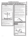
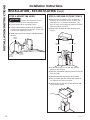
STEP 1: INSTALL FRAMING FOR
HOOD SUPPORT
IMPORTANT: Framing must be capable of
supporting 100 lbs.
If drywall is present, mark the screw hole locations
for the top mounting brackets. Remove the
template.
Ŷ Cut away enough drywall to expose 2 vertical
studs at the bracket location indicated on the
template.
Ŷ Install a horizontal support at least 1” x 12”
between two wall studs at the mounting screw
location. The horizontal support must be flush
with the room side of the studs. Use cleats
behind both sides of the support to secure to wall
studs.
NOTE: 2 horizontal supports will be needed if there
is a stud located between the horizontal screw
locations (see figure).
IMPORTANT: Reinstall drywall for an even
mounting surface.
REAR WALL
MOUNTING TEMPLATE
Vertical Centerline
ALIGN BOTTOM EDGE
WITH PENCIL LINE
INDICATING BOT TOM
OF THE HOOD
11-7/16"
Installation Height
Horizontal Line
C
L
DRILL 2 (TWO) 3/16" PILOT HOLES THROUGH STUDS OR REAR WALL SUPPORT
10-1/8"
12-08 JR
2"
DRILL 2 (TWO) 3/16" PILOT HOLES THROUGH STUDS OR REAR WALL SUPPORT
12-1/2"
WALL VENT IS 27-3/4" MIN.
ABOVE THE INSTALLATION
HEIGHT
31-14772 Printed in Mexico
Ceiling
House
Wiring
Location C
L
5”
´
Min.
Wall vent
´
min.
above
installation
height
5” c enterline
to wall
View from
rear cleats
1” x 12” min.
mounting
support
´PLQRSHQLQJIRUGXFWZRUN
Centerline of
installation space

49-7000197 Rev. 0 15
Installation Instructions
INSTALLATION - VENTED TO THE OUTSIDE (Cont.)
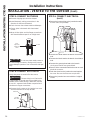
STEP 2: INSTALL HOOD MOUNTING
SCREWS
The two upper mounting screws must enter the
horizontal support or wall studs.
Ŷ:LWKWKHWHPSODWHWDSHGLQSODFHXVHDSXQFKWR
mark mounting bracket screw locations.
Ŷ'ULOO´SLORWKROHVLQRIWKHSXQFKHGORFDWLRQV
in the lower bracket. If the bottom 2 pilot holes
GRQRWHQWHUZRRGHQODUJHWKHKROHVWR´DQG
install metal wall fastener anchors (provided).
Ŷ5HPRYHWKHWHPSODWH
Ŷ,QVWDOOWKHWRSPRXQWLQJVFUHZVOHDYH´
gap between the screw head and the wall. This
will allow the keyhole slot on the hood frame to
engage the screw head.
IMPORTANT: Use the mounting screws provided.
DO NOT USE DRYWALL SCREWS.
Ŷ&KHFNWREHVXUHWKHPRXQWLQJVFUHZVDUH
horizontally level.
STEP 3: INSTALL DUCT BRACKET
The duct bracket should be installed against the
EDFNZDOODQGIOXVKZLWKWKHFHLOLQJWKHSRLQWZKHUH
the ceiling meets the wall should be level for the
bracket and duct cover to fit flush. This bracket will
hold the duct cover in place at the top.
Secure the bracket to the wall:
Ŷ$OLJQWKHGLDPRQGFHQWHUOLQHFXWRXWRQWKH
bracket with the penciled centerline on the wall.
Ŷ0DUNVFUHZKROHORFDWLRQVLQWKHZDOO
Ŷ'ULOO´SLORWKROHVLQWKHPDUNHGORFDWLRQV
Ŷ,ISLORWKROHVGRQRWHQWHUZRRGVWXGVHQODUJH
WKHKROHVWR´DQGLQVWDOOPHWDOZDOOIDVWHQHU
anchors (provided).
Ŷ,IPRXQWLQJGLUHFWO\WRDPDVRQU\ZDOOREWDLQ
appropriate #10 masonry screw anchors. Drill and
install per the fastener supplier’s instructions.
Ŷ'ULYHVFUHZVE\KDQGLQWRWKHIDVWHQHUVWRDOORZ
anchors to expand. Remove the screws.
Ŷ6HFXUHWKHEUDFNHWWRWKHZDOOZLWKZRRGVFUHZV
DQGRUIDVWHQHUV
STEP 4: MOUNT THE HOOD
WARNING 2 people are required to lift and
position the hood onto the mounting screws.
Ŷ/LIWWKHKRRGRQWRWKHPRXQWLQJVFUHZV
Ŷ,IXVLQJDZDOOIDVWHQHUPDNHVXUHWKHZDVKHULV
in front of the flange and not behind it. Check with
a level before tightening the screws.
Ŷ,QVWDOOORZHUVFUHZVWRSXOOWKHKRRGWLJKWDJDLQVW
the wall.
INSTALLATION INSTRUCTIONS
REAR WALL
MOUNTING TEMPLATE
Vertical Centerline
ALIGN BOTTOM EDGE
WITH PENCIL LINE
INDICATING BOTTOM
OF THE HOOD
11-7/16"
Installation Height
Horizontal Line
C
L
DRILL 2 (TWO) 3/16" PILOT HOLES THROUGH STUDS OR REAR WALL SUPPORT
10-1/8"
12-08 JR
2"
DRILL 2 (TWO) 3/16" PILOT HOLES THROUGH STUDS OR REAR WALL SUPPORT
12-1/2"
WALL VENT IS 27-3/4" MIN.
ABOVE THE INSTALLATION
HEIGHT
31-14772 Printed in Mexico
Centerline cutout
Tighten screws
Install
screws
Bottom
screw
location

16 49-7000197 Rev. 0
Installation Instructions
INSTALLATION INSTRUCTIONS
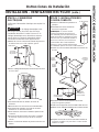
INSTALLATION - VENTED TO THE OUTSIDE (Cont.)
STEP 5: CONNECT DUCTWORK
Ŷ Remove shipping tape from the damper.
Ŷ Install ductwork, making connections in the
direction of airflow as illustrated.
Ŷ Push duct over the exhaust outlet and damper.
Ŷ Secure joints in ductwork with sheet metal
screws.
Ŷ Wrap all duct joints and the flange connections
with aluminized duct tape for an airtight seal.
CAUTION Do not use sheet metal screws at
the hood flange connection. Doing so will prevent
proper damper operation. Seal connection with tape
only.
STEP 6: CONNECT ELECTRICAL
Verify that power is turned off at the source.
WARNING If house wiring is not 2-wire with
a ground wire, a ground must be provided by the
installer. When house wiring is aluminum, be sure
to use U.L. approved anti-oxidant compound and
aluminum-to-copper connectors.
Ŷ Remove the 6 screws on the junction box cover
and the knockout on the top left side.
STEP 6: CONNECT ELECTRICAL
(cont.)
Ŷ6HFXUHWKHKRXVHZLULQJWRWKHMXQFWLRQER[ZLWK
a strain relief (not provided).
Ŷ&RQQHFWWKHZKLWHOHDGWRWKHEUDQFKFLUFXLWZKLWH
lead.
Ŷ&RQQHFWWKHEODFNOHDGWRWKHEUDQFKFLUFXLWEODFN
lead.
Ŷ&RQQHFWWKHJUHHQ\HOORZOHDGWRWKHEUDQFK
circuit green lead or bare ground lead.
Ŷ6HFXUHDOOWKHFRQQHFWLRQVZLWKZLUHQXWVRQHDFK
electrical connector.
Ŷ3XVKWKHZLUHVLQWRWKHMXQFWLRQER[DQGUHSODFH
the cover. Be sure the wires are not pinched.
Ŷ6HFXUHWKHMXQFWLRQER[FRYHUZLWKWKHRULJLQDO
screws.
Duct
tape over
seam and
screw
Screw
Airflow
Junction
box cover
Knockout

49-7000197 Rev. 0 17
Installation Instructions
INSTALLATION - VENTED TO THE OUTSIDE (Cont.)
INSTALLATION INSTRUCTIONS
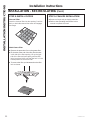
STEP 7: INSTALL DUCT COVERS
Ŷ5HPRYHSURWHFWLYHSODVWLF
covering.
Ŷ$VVHPEOHGXFWFRYHUV
according to application.
NOTE: The inside duct cover
has vent holes on one end.
The holes are intended for
use when the hood is installed for recirculating
purposes. Slide the upper duct cover into the folded
ends of the lower duct cover.
Ŷ3ODFHWKHGHFRUDWLYHGXFWFRYHUVRQWRSRIWKH
hood.
Ŷ([WHQGWKHLQQHUGXFWFRYHUXSZDUGWRWKHFHLOLQJ
bracket.
Ŷ6HFXUHZLWKVFUHZVWRWKHGXFWFRYHUEUDFNHW
Ŷ5HPRYHWKHSDFNLQJPDWHULDOIURPWKHILOWHU
opening.
Ŷ/RFDWHWKHVFUHZKROHVRQWKHLQVLGHIURQWHGJHRI
the opening. Install 2 screws to secure the lower
duct cover to the hood.
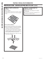
STEP 8: INSTALL METAL GREASE
FILTER
Ŷ5HPRYHWKHSURWHFWLYHILOPRQWKHJUHDVHILOWHU
NOTE: The charcoal filter is not required for this
installation.
Ŷ)LWWKHWDEVDWWKHHQGRIWKHILOWHULQWRWKHVORWVLQ
the left side of the filter opening. Lift up the right
side of the filter and push gently until the filter
locks into place. Make sure the filter lock is in the
closed position to secure the filter.
Ŷ7RUHPRYHWKHILOWHUSXOOGRZQZDUGRQWKHILOWHU
lock to release.
STEP 9: FINALIZE INSTALLATION
Ŷ&KHFNWREHVXUHDOOWDSHDQGSDFNDJLQJ
materials have been removed.
Ŷ5HIHUWRWKH2SHUDWLQJ,QVWUXFWLRQVLQWKLVPDQXDO
to operate the hood.
Mounting
screws
Lower duct
cover seat
Duct cover bracket
Lower
duct cover
Upper
duct cover
Duct cover
attachment
tabs
Screw holes

49-7000197 Rev. 0
Installation Instructions
INSTALLATION INSTRUCTIONS
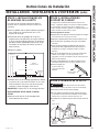
INSTALLATION - RECIRCULATING
DUCTWORK, WIRING LOCATIONS
Ŷ'HWHUPLQHWKHH[DFWORFDWLRQRIWKHYHQWKRRG
Ŷ/RFDWHWKHWHPSODWHSDFNHGZLWKWKHOLWHUDWXUH
Ŷ0HDVXUHIURPWKHIORRUWRWKHWRSRIWKHFRRNLQJ
surface. Add hood installation height determined
RQSDJHVDQG0DUNWKDWORFDWLRQ
Ŷ7DSHWKHWHPSODWHLQSRVLWLRQDORQJWKHSHQFLOHG
line. CHECK TO BE SURE THE TEMPLATE IS
LEVEL.
Ŷ8VHDOHYHOWRGUDZDOLQHVWUDLJKWXSIURPWKH
centerline on the template to the ceiling.
HOUSE WIRING LOCATION:
Ŷ7KHMXQFWLRQER[LVORFDWHGRQWKHWRSOHIWVLGHRI
the hood.
Ŷ:LULQJVKRXOGHQWHUWKHEDFNZDOODWOHDVW´
above the bottom of the hood, and within 5” of the
centerline.
STEP 1: INSTALL FRAMING FOR
HOOD SUPPORT
IMPORTANT: Framing must be capable of
supporting 100 lbs.
If drywall is present, mark the screw hole locations
for the top mounting brackets. Remove the
template.
Ŷ&XWDZD\HQRXJKGU\ZDOOWRH[SRVHYHUWLFDO
studs at the bracket location indicated on the
template.
Ŷ,QVWDOODKRUL]RQWDOVXSSRUWDWOHDVW´[´
between two wall studs at the mounting screw
location. The horizontal support must be flush
with the room side of the studs. Use cleats
behind both sides of the support to secure to wall
studs.
NOTE: 2 horizontal supports will be needed if there
is a stud located between the horizontal screw
locations (see figure).
IMPORTANT: Reinstall drywall for an even
mounting surface.
REAR WALL
MOUNTING TEMPLATE
Vertical Centerline
ALIGN BOTTOM EDGE
WITH PENCIL LINE
INDICATING BOTTOM
OF THE HOOD
11-7/16"
Installation Height
Horizontal Line
C
L
DRILL 2 (TWO) 3/16" PILOT HOLES THROUGH STUDS OR REAR WALL SUPPORT
10-1/8"
12-08 JR
2"
DRILL 2 (TWO) 3/16" PILOT HOLES THROUGH STUDS OR REAR WALL SUPPORT
12-1/2"
WALL VENT IS 27-3/4" MIN.
ABOVE THE INSTALLATION
HEIGHT
31-14772 Printed in Mexico
Ceiling
House Wiring
Location CL
5”
´
Min.
5” c enterline to wall
View from
rear cleats
1” x 12” min.
mounting
support
Centerline of
installation
space

49-7000197 Rev. 0 19
Installation Instructions
INSTALLATION - RECIRCULATING (Cont.)
INSTALLATION INSTRUCTIONS
STEP 2: INSTALL HOOD MOUNTING
SCREWS
The mounting screws must enter the horizontal
support or wall studs.
Ŷ With the template taped in place, use a punch to
mark mounting bracket screw locations.
Ŷ'ULOO´SLORWKROHVLQRIWKHSXQFKHGORFDWLRQV
in the lower bracket. If the bottom 2 pilot holes
GRQRWHQWHUZRRGHQODUJHWKHKROHVWR´DQG
install metal wall fastener anchors (provided).
Ŷ Remove the template.
Ŷ,QVWDOOWKHWRSPRXQWLQJVFUHZVOHDYH´
gap between the screw head and the wall. This
will allow the keyhole slot on the hood frame to
engage the screw head.
IMPORTANT: Use the mounting screws provided.
DO NOT USE DRYWALL SCREWS.
• Check to be sure the mounting screws are
horizontally level.
STEP 3: INSTALL DUCT BRACKET
AND DEFLECTOR
The duct bracket should be installed against the
EDFNZDOODQGIOXVKZLWKWKHFHLOLQJWKHSRLQW
where the ceiling meets the wall should be level
for the bracket and duct cover to fit flush. This
bracket will hold the duct cover in place at the top.
Secure the bracket to the wall:
Ŷ Align the diamond centerline cutout on the
bracket to the penciled centerline on the wall.
Ŷ Mark 2 screw hole locations in the wall.
Ŷ 'ULOO´SLORWKROHVLQWKHPDUNHGORFDWLRQV
Ŷ If pilot holes do not enter wood studs, enlarge
WKHKROHVWR´DQGLQVWDOOPHWDOZDOOIDVWHQHU
anchors (provided).
Ŷ If mounting directly to a masonry wall, obtain
appropriate #10 masonry screw anchors.
Drill and install per the fastener supplier’s
instructions.
Ŷ Drive screws, by hand, into the fasteners to
allow anchors to expand. Remove the screws.
Ŷ Secure the bracket to the wall with wood screws
DQGRUIDVWHQHUV
Ŷ Assemble the air deflector accessory to the
duct cover bracket with the 4 assembly screws
provided. DO NOT tighten screws. This is a
temporary installation.
REAR WALL
MOUNTING TEMPLATE
Vertical Centerline
ALIGN BOTTOM EDGE
WITH PENCIL LINE
INDICATING BOTTOM
OF THE HOOD
11-7/16"
Installation Height
Horizontal Line
C
L
DRILL 2 (TWO) 3/16" PILOT HOLES THROUGH STUDS OR REAR WALL SUPPORT
10-1/8"
12-08 JR
2"
DRILL 2 (TWO) 3/16" PILOT HOLES THROUGH STUDS OR REAR WALL SUPPORT
12-1/2"
WALL VENT IS 27-3/4" MIN.
ABOVE THE INSTALLATION
HEIGHT
31-14772 Printed in Mexico
Centerline cutout

20 49-7000197 Rev. 0
Installation Instructions
INSTALLATION - RECIRCULATING (Cont.)
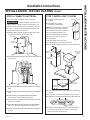
STEP 4: MOUNT THE HOOD
WARNING 2 people are required to lift and
position the hood onto the mounting screws.
Ŷ Lift the hood onto the mounting screws.
Ŷ,IXVLQJDZDOOIDVWHQHUPDNHVXUHWKHZDVKHULV
in front of the flange and not behind it. Check with
a level before tightening screws.
Ŷ,QVWDOOORZHUVFUHZVWRSXOOWKHKRRGWLJKWDJDLQVW
the wall.
STEP 5: SIZE AND CUT DUCT PIECE
Ŷ Measure from the bottom of the air deflector
to the top of the hood as shown. Reduce that
dimension by 1” to facilitate installation. The
duct will cover and overlap the deflector and the
exhaust outlet in the hood.
Ŷ5HPRYHWKHDLUGHIOHFWRUIURPWKHGXFWFRYHU
bracket.
Ŷ&XWWKHGXFWSLHFHWRVL]HDQGVOLSRQWRWKH
bottom of the deflector.
Ŷ3ODFHWKHDVVHPEOHGGHIOHFWRUDQGGXFWRYHUWKH
exhaust outlet.
Ŷ+ROGWKHDVVHPEO\DJDLQVWWKHGXFWEUDFNHW
Ŷ'ULYHVFUHZVLQWRHDFKVLGHRIWKHERWWRPRI
the deflector and into the bracket.
Ŷ8VHGXFWWDSHWRVHDOGXFWWRWKHGHIOHFWRUDQG
at the exhaust outlet.
INSTALLATION INSTRUCTIONS
Tighten
screws
Install
screws
Bottom
screw
location
Measure
length Duct length
Deflector
La page est en cours de chargement...
La page est en cours de chargement...
La page est en cours de chargement...
La page est en cours de chargement...
La page est en cours de chargement...
La page est en cours de chargement...
La page est en cours de chargement...
La page est en cours de chargement...
La page est en cours de chargement...
La page est en cours de chargement...
La page est en cours de chargement...
La page est en cours de chargement...
La page est en cours de chargement...
La page est en cours de chargement...
La page est en cours de chargement...
La page est en cours de chargement...
La page est en cours de chargement...
La page est en cours de chargement...
La page est en cours de chargement...
La page est en cours de chargement...
La page est en cours de chargement...
La page est en cours de chargement...
La page est en cours de chargement...
La page est en cours de chargement...
La page est en cours de chargement...
La page est en cours de chargement...
La page est en cours de chargement...
La page est en cours de chargement...
La page est en cours de chargement...
La page est en cours de chargement...
La page est en cours de chargement...
La page est en cours de chargement...
La page est en cours de chargement...
La page est en cours de chargement...
La page est en cours de chargement...
La page est en cours de chargement...
La page est en cours de chargement...
La page est en cours de chargement...
La page est en cours de chargement...
La page est en cours de chargement...
La page est en cours de chargement...
La page est en cours de chargement...
La page est en cours de chargement...
La page est en cours de chargement...
La page est en cours de chargement...
La page est en cours de chargement...
La page est en cours de chargement...
La page est en cours de chargement...
La page est en cours de chargement...
La page est en cours de chargement...
La page est en cours de chargement...
La page est en cours de chargement...
La page est en cours de chargement...
La page est en cours de chargement...
La page est en cours de chargement...
La page est en cours de chargement...
La page est en cours de chargement...
La page est en cours de chargement...
-
 1
1
-
 2
2
-
 3
3
-
 4
4
-
 5
5
-
 6
6
-
 7
7
-
 8
8
-
 9
9
-
 10
10
-
 11
11
-
 12
12
-
 13
13
-
 14
14
-
 15
15
-
 16
16
-
 17
17
-
 18
18
-
 19
19
-
 20
20
-
 21
21
-
 22
22
-
 23
23
-
 24
24
-
 25
25
-
 26
26
-
 27
27
-
 28
28
-
 29
29
-
 30
30
-
 31
31
-
 32
32
-
 33
33
-
 34
34
-
 35
35
-
 36
36
-
 37
37
-
 38
38
-
 39
39
-
 40
40
-
 41
41
-
 42
42
-
 43
43
-
 44
44
-
 45
45
-
 46
46
-
 47
47
-
 48
48
-
 49
49
-
 50
50
-
 51
51
-
 52
52
-
 53
53
-
 54
54
-
 55
55
-
 56
56
-
 57
57
-
 58
58
-
 59
59
-
 60
60
-
 61
61
-
 62
62
-
 63
63
-
 64
64
-
 65
65
-
 66
66
-
 67
67
-
 68
68
-
 69
69
-
 70
70
-
 71
71
-
 72
72
-
 73
73
-
 74
74
-
 75
75
-
 76
76
-
 77
77
-
 78
78


GE Profile UVW7301SWSS Le manuel du propriétaire
- Catégorie
- Hottes
- Taper
- Le manuel du propriétaire
- Ce manuel convient également à
dans d''autres langues
Documents connexes
Autres documents
-
GE ZV830SMSS Guide d'installation
-
Monogram ZV900SLSS Guide d'installation
-
-
GE ZV30HSRSS Guide d'installation
-
-
 GE Monogram GEZV48RSFSS DL 455a362e561c07b96069ab446b42
-
Hotpoint JV248 Le manuel du propriétaire
-
 GE Monogram GEZV950SDSS DL 5d7bc61df13207f0d1d3b946cc81
-
GE Appliances UVC9300SLSS Le manuel du propriétaire
-
Parrot Uncle F6356110V Guide d'installation

