12
Dwg Name: VDV500-820-1390301ART
Dwg No: 1390301 Rev: G
Pkg Dwg Ref: 1790 ECO No: 041011
Finish Coat Requirements: N/A
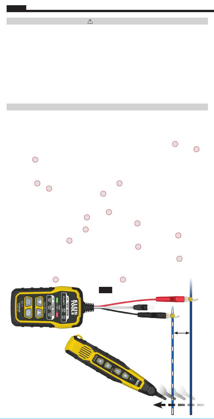
2"
(51 mm)
FIG. 1
ESPAÑOL
ADVERTENCIAS
Para garantizar el funcionamiento y servicio seguros de los instrumentos, siga estas instrucciones.
Elincumplimiento de estas advertencias puede provocar un incendio, choque eléctrico, lesiones
gravesola muerte.
• El Toner-Pro y Probe-Pro están diseñados para usarse en sistemas de cableado de voltaje extra bajo
(menos de 60voltios) para pruebas cuando estos sistemas NO ESTÁN energizados.
• La tensión máxima entre los cordones de prueba ABN del Toner-Pro es de 60voltios en el modo de Prueba
y de 20voltios en el modo de continuidad. Conectar el Probe-Pro a una fuente de alimentación de CA
activa puede dañarlo e implicar un riesgo de seguridad para el usuario.
• NO utilice los instrumentos si están húmedos dado que podrían representar un riesgo de choque eléctrico.
• NO utilice los instrumentos si están dañados.
• Apague los instrumentos y desconecte todos los cordones de prueba ABN antes de intentar reemplazar las baterías.
• La tapa del compartimiento de las baterías debe estar ajustada en su lugar antes de operar el instrumento.
• NO abra la carcasa, excepto el compartimiento de las baterías.
INSTRUCCIONES DE FUNCIONAMIENTO
LEA TODAS LAS INSTRUCCIONES ANTES DE UTILIZAR LOS DISPOSITIVOS Y CONSÉRVELAS PARA
CONSULTARLAS EN EL FUTURO.
PRUEBA DE CONTINUIDAD
El Toner-Pro transmite frecuencias sobre alambres no energizados únicamente. Al encender el Toner-Pro,
se realizará una prueba de continuidad para determinar si los dos alambres que van a trazarse están muy
cerca uno del otro, sin un circuito conductor entre ellos. El indicador CONT (continuidad)
T4
se iluminará
de color verde para dar la indicación de aprobación. Sujete los cordones de prueba ABN rojo y negro
T14
a
los alambres que van a probarse. Si la resistencia del circuito es inferior a 10kΩ, entonces el indicador CONT
(continuidad)
T4
se iluminará de color rojo, indicando un cortocircuito y no se podrán identificar cables. Si el
indicador CONT (continuidad) se ilumina de color verde, entonces se producirá un tono y podrá continuar.
SELECCIÓN DE LA FRECUENCIA DE TONO
La frecuencia predeterminada del Toner-Pro cuando está encendido es de 800Hz. Utilice el botón de aumento
del modo Tono
T8
y el botón de disminución del modo Tono
T7
para cambiar la frecuencia. Los indicadores
de frecuencia de tono
T6
mostrarán la frecuencia transmitida. Si se selecciona un tono alternante, los dos
indicadores de frecuencia de tono correspondientes
T6
parpadearán.
Los tonos recorrerán las frecuencias
disponibles en un ciclo continuo al presionar un botón de aumento o disminución de forma repetida.
TRAZADO DE PARES DE ALAMBRES (FIG. 1)
1. Conecte el cordón de prueba ABN rojo del Toner-Pro
T14
a uno de los alambres del par que va a trazarse.
Conecte el cordón de prueba ABN negro
T14
al otro alambre que va a trazarse.
2. Encienda el Toner-Pro presionando el botón de encendido y apagado
T9
.
3. Revise el indicador CONT (continuidad)
T4
. Si está iluminado de color verde, entonces puede continuar.
4. Seleccione la configuración de tono preferida utilizando el botón de
aumento del modo Tono
T8
o el botón
de
disminución del modo Tono
T7
.
5. Encienda el Probe-Pro presionando el botón de encendido y apagado
P5
.
6. De ser posible, cree en el extremo del cable una separación de 2" (51mm) entre los cables.
7. Utilice el Probe-Pro para escanear los pares de alambres del cable. Mueva la punta del Probe-Pro
P1
lentamente
a lo largo de los alambres (FIG. 1). El volumen del Probe-Pro aumentará a medida que se acerca al par con tono.
Cuando el volumen del Probe-Pro es alto sobre el primer alambre, bajo en medio de (entre) los dos alambres y
alto sobre el segundo alambre, entonces habrá encontrado el par de alambres que está rastreando. Utilice el botón
de
aumento de volumen
P6
y el botón de
reducción de volumen
P7
para ajustar el volumen.
VDV500-820-1390301ART - Pro Tone and Probe Kit.indd 12VDV500-820-1390301ART - Pro Tone and Probe Kit.indd 12 7/30/21 10:26 AM7/30/21 10:26 AM


