HUANUO HNCM7 Manuel utilisateur
- Catégorie
- Supports de bureau à panneau plat
- Taper
- Manuel utilisateur

(A
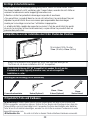
Monitor Desk Mount
Instruction Manual
Model: HNCM7
English ------------------------ 01-07
Deutsch ------------------------ 08-14
Français ------------------------ 15-21
Español ------------------------ 22-28
Italiano ------------------------ 29-35
Thank you for choosing this HUANUO product! At HUANUO, we strive to provide you with
the best quality products and services in the industry. Should you have any issues, please
don't hesitate to contact us.
Technical Support:
(US/CA)1-800-556-0533 Mon-Fri 8am - 8pm(CST)
(UK)44-808-196-3874 Mon-Fri 2pm - 10pm(UTC
Other Info:
Website: www.huanuoav.com
Manufacturer: BESTQI INNOATION (HONGKONG)TECHNOLOGY CO.,LIMITED
Address: RM21 UNIT A 11/F TIN WUI ING BLDG NO 3 HING WONG ST TUEN MUN NT HONGKONG
AMZLAB GmbH
Laubenhof 23,45326 Essen
THEMIS AR support ltd.
85 Great Portland St, London, United Kingdom.

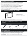
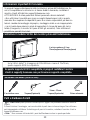
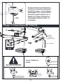
Tools Needed (Not Included)
Phillips Screwdriver
Please carefully read all instructions before attempting installation. If you do not
understand the instructions or have any concerns or questions, please contact
our customer service at [email protected].
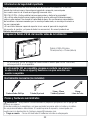
CAUTION: Avoid potential personal injuries and property damage!
• Do not use this product for any purpose that is not explicitly speci ed in this
manual. Do not exceed weight capacity. We are not liable for damage or injury
caused by incorrect assembly or inappropriate use.
• The desk must be capable of supporting ve times the weight of the monitor
and mount combined.
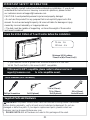
Check the VESA Pattern of Your Monitor before the Installation
IMPORTANT SAFETY INFORMATION
If your monitor VESA is greater than 100x100 mm/4x4 in or less than
VESA 75x75 mm/3x3 in, this mount is NOT compatible.
If this mount is NOT compatible, please contact customer service at
[email protected] to nd a compatible mount.
MAX: 100mm/4 in
MAX: 100mm/4 in
Minimum VESA pattern:
75mm/3 in(W)x75mm/3 in(H)
100 mm 4 in
75 mm 3 in
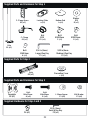
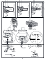
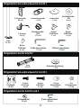
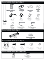
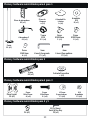
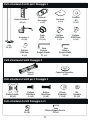
Supplied Parts and Hardware
WARNING: This product contains small items that could be a choking hazard if swallowed.
Before starting assembly, verify all parts are included and undamaged. Do not use
damaged or defective parts. lf you require replacement parts, please contact our
customer service at [email protected].
• PLEASE NOTE: Not all hardware included in this package will be used.
01
3/8 in (10mm)
Socket Wrench
Drill(Optional)
7/16 in (11mm) -
7/8 in (22mm)
Drill(Optional)

Supplied Parts and Hardware for Step 1
02
Supplied Hardware for Step 4 and 5
1/8 in (3mm)
Small Allen Key
F3 (x1)
Nut
F4 (x2)
Washer
M6
D (x1)
Nut
M10
E2 (x1)
Bolt
M6X12mm
F (x1)
Bolt
M8X10mm
G (x2)
3/16 in (5mm)
Large Allen Key
F1
(x1)
5/32 in (4mm
Medium Allen Key
F2 (x1)
Locking Plate
a (x1)
C-Clamp Brace
02 (x1)
C-Clamp
03 (x1)
Pole
01 (x1)
Bottom Pad
b (x1)
Bolt
M6X8mm
H (x2)
Supplied Parts for Step 2
Decorative Cover
c (x1)
Arm
04 (x1)
Supplied Parts and Hardware for Step 3
Faceplate
05 (x2)
Bolt
M4x12mm
A (x8)
Bolt
M4x30mm
B (x8) L13mm Spacer
C1 (x8) M4 Washer
C2 (x8)

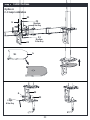
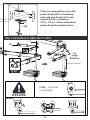
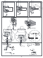
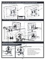
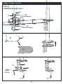
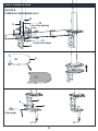
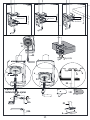
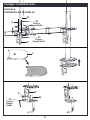
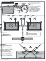
Step 1
Option A
C-Clamp Installation
Install the Base
03
02
02
01
03
Medium
Allen Key
Large
Allen Key
F2
H
F
Medium
Allen Key
F2
b
G
F1

04
Desk
Thickness
2 3/16 in (55mm) - 3 5/32 in (80mm)
Desk
Thickness
1 3/16 in (30mm) - 2 3/16 in (55mm)
Desk
Thickness
3/8 in (10mm) - 1 3/16 in (30mm)
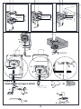
b
Option B:
Grommet Installation
b
03a
03b
03b
01
03
D
a
03
D a
Tighten
D
a
D
a

05
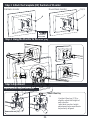
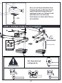
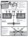
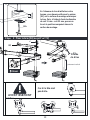
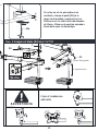
Step 2 Secure the Arm [04] to the Pole [01]
If there is no grommet hole on your desk,
position the pole [01] on the mounting
surface and mark the hole. Drill a hole
using the drill bit in a diameter of
7/16 in - 7/8 in (11-22mm) at the marked
position through the mounting surface.
03b
3/4 in - 3 5/32 in
(20-80mm)
7/16 in - 7/8 in
(11-22mm)
a
E2
F1
c
Large
Allen Key
UP DeskDesk DeskDesk
Height Adjustment
04
01
WARNING
CASE If the head
is not straight.
Solution

06
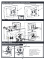
A
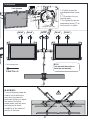
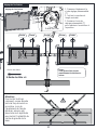
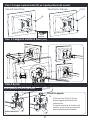
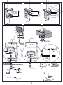
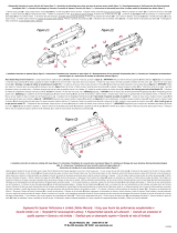
Step 4 Hang the Monitor to the Arm [04]
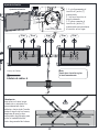
Step 5 Adjustment
Step 3 Attach the Faceplate [05] the Back of Monitor
Use the Allen key [F3] to
slightly adjust the height of
each monitor.
Individual monitor height
adjustment helps monitors to
be perfectly aligned.
B
C1/C2
Flat back monitor Round back monitor
Small Allen Key
F3
Remove the nut [F4]
Slightly Adjust the Height of each Monitor
Phillips
Screwdriver
Not Included
F4
F4

07
1. Slightly loosen the
pre-assembled set screw
[T] .
2. Tilt monitor to your
desired angle.
3. Re-tighten the pre-as-
sembled set screw [T] to
hold monitor in place.
WARNING:
To avoid tipping, please be
careful not to extend the
arms too far forward or
backward. When you adjust
the angle of the arms,
please make sure two arms
are balanced to avoid
instability of the center of
gravity of the base.
F1
Tilt Adjustment
Large Allen Key
Tilt Adjustment
T
Swivel Swivel SwivelSwivel Swivel
Cable management
Cable Tie x 6
NOTE:
You can rotate the monitor or
swivel the arm manually.

08
Minimales VESA Muster:
75mm (Breite) x75mm (Höhe)
MAX:100mm
MAX:100mm
Benötigtes Werkzeug (nicht enthalten)
Kreuzschraubendreher
Bitte lesen Sie alle Anweisungen sorgfältig durch, bevor Sie instal lieren. Wenn
Sie dieses Handbuch nicht verstehen oder Fragen haben, wenden Sie sich bitte an
unseren Kundenservice unter [email protected].
Attention: évitez les potentiels dommages corporels et aux biens.
• Ne pas utilizer ce produit dans le cas où cet instruction n’a pas indiqué. Ne pas
dépasser le poids limité. Nous ne sommes pas responsables des dommages
causés par le montage incorrect ou l’utilisation inappropriée.
• La table doit être capable de supporter au moins 5 fois du poids total (les poids
du socle, le moniteur et tous les accessoires), ne pas utiliser ce pruoduit dans un
panneau des particules.
Überprüfen Sie vor der Installation das VESA Muster des Monitore
Wichtige Sicherheitshinweise
Wenn Ihr Monitore-VESA größer als 100 x 100 mm oder weniger als
75x75mm ist, ist diese Installation NICHT kompatibel.
Wenn diese Halterung NICHT kompatibel ist, wenden Sie sich an den
Kundendienst unter [email protected], um eine kompatible
Installation zu nden.
Mitgelieferte Teile und Hardware
WARNUNG: Dieses Produkt enthält kleine Gegenstände, die beim Verschlucken eine
Erstickungsgefahr verursachen können. Stellen Sie vor Beginn der Montage sicher, dass alle
Teile enthalten und nicht beschädigt sind. Verwenden Sie keine beschädigten oder defekten
Teile. Wenn Sie Ersatzteile benötigen, wenden Sie sich bitte an unseren Kundenservice unter
• Bitte beachten Sie: Es wird nicht alle in diesem Paket enthaltene Hardware verwendet.
10mm
SteckschlüsselBohrer(Optional) 11mm - 22mm
Bohrer(Optional)

09
Mitgelieferte Teile und Hardware für Schritt 1
Mitgelieferte Teile für Schritt 4 und 5
3mm
Kleiner Inbusschlüssel
F3 (x1)
Schraubenmutter
F4 (x2)
Unterlegscheibe
M6
D (x1)
Schraubenmutter
M10
E2 (x1)
Bolzen
M6X12mm
F (x1)
Bolzen
M8X10mm
G (x2)
5mm
Großer Inbusschlüsse
F1
(x1)
4mm
Mittlerer Inbusschlüssel
F2 (x1)
Verriegelungsplatte
a (x1)
C-Klemm platte
02 (x1)
C-Klemme
03 (x1)
Mast
01 (x1)
Unteres Pad
b (x1)
Bolzen
M6X8mm
H (x2)
Mitgelieferte Teile für Schritt 2
Dekorative Abdeckung
c (x1)
Arm
04 (x1)
Mitgelieferte Teile und Hardware für Schritt 3
Frontplatte
05 (x2)
Bolzen
M4x12mm
A (x8)
Bolzen
M4x30mm
B (x8)
L13mm
Abstandshalter
C1 (x8)
M4
Unterlegscheibe
C2 (x8)

10
Schritt 1 Basis Installation
Option A
Installation der C-Klemme
03
02
02
01
Mittlerer Inbusschlüssel
Großer
Inbusschlüssel
F2
H
F
Mittlerer Inbusschlüssel
F2
b
G
F1

11
Tischdicke
55mm - 80mm
Tischdicke
30mm - 55mm
Tischdicke
10mm - 30mm
b
Option B:
Tülleninstallation
b
03a
03b
03b
01
Festziehen
Schreibtisch
03
D
a
03
D a
D
a
D
a

12
Schritt 2 Befestigen Sie den Arm [04] am Mast [01]
Wenn sich auf Ihrem Schreibtisch kein
Ösenloch be ndet, positionieren Sie den
mast [01] auf der Montage äche und
markieren Sie das Loch. Bohren Sie mit
dem Bohrer ein Loch mit einem
Durchmesser von 11mm oder 22mm an
der markierten.
F1
c
04
01
Großer
Inbusschlüssel
OBEN Schreibtisch Schreibtisch
Höheneinstellung
03b
20-80mm
11-22mm
a
WARNUNG
Fall: Wenn der Kopf
nicht gerade ist.
Lösung
E2

13
A
Schritt 4 Hängen Sie den Monitor an den Arm [04]
Schritt 5 Einstellung
Schritt 3 Bringen Sie die Frontplatte [05] an der Rückseite des Monitors an
Verwenden Sie die Inbus-Taste
[F3], um die Höhe jedes Monitors
leicht anzupassen.
Durch die individuelle
Höheneinstellung des Monitors
können die Monitore perfekt
ausgerichtet werden.
B
C1/C2
Für Monitor mit Flachbildschirm Für Monitor mit Curved Bildschirm
Kleiner Inbusschlüssel
F3
Entfernen Sie die Mutter [F4]
Passen Sie die Höhe jedes Monitors leicht an
F4
F4
Kreuzschraubendrehe
(nicht enthalten)

14
1. Lösen Sie die
vormontierte Stellschraube
[T] leicht.
2. Neigen Sie den Monitor in
den gewünschten Winkel.
3. Ziehen Sie die
vormontierte Stellschraube
[T] wieder an, um den
Monitor an Ort und Stelle zu
halten.
Warnung:
Um ein Umkippen zu
vermeiden, achten Sie bitte
darauf, die Arme nicht zu weit
nach vorne oder hinten zu
strecken.Wenn Sie den Winkel
der Arme einstellen, stellen
Sie bitte sicher, dass zwei
Arme ausgeglichen sind, um
eine Instabilität des
Schwerpunkts der Basis zu
vermeiden.
F1
Neignungseinstellung
Schwenkbar Schwenkbar Schwenkbar Schwenkbar Schwenkbar
Neignungseinstellung
Kabel ManageAVment
Kabelbinder x 6
Hinweis:
Sie können den Monitor
drehen oder den Arm manuell
schwenken.
T
Großer Inbusschlüssel

15
Modèle VESA minimal :
75mm (largeur) x75mm (hauteur)
Maximum:
100mm
Maximum:
100mm
Outils nécessaires (pas compris)
Tournevis cruciform
Veuillez bien lire tous les instructiona avant du montage. Si vous ne comprenez
pas les instructions ou avez des questions, contactez s’il vous plaît le service
client par [email protected].
Attention: évitez les potentiels dommages corporels et aux biens!
• Ne pas utilizer ce produit dans le cas où cet instruction n’a pas indiqué. Ne pas
dépasser le poids limité. Nous ne sommes pas responsables des dommages
causés par le montage incorrect ou l’utilisation inappropriée
• La table doit être capable de supporter au moins 5 fois du poids total (les
poids du socle, le moniteur et tous les accessoires), ne pas utiliser ce pruoduit
dans un panneau des particules.
Véri er le Modèle VESA du Moniteur avant l’Installation
Information De Sécuritaire Importante
Si votre moniteur VESA est plus grande que 100*100mm, ou plus petite
que 75*75mm. Ce montage n’est pas compatible.
Si ce montage n’est pas compatible, veuillez s’il vous plaît contacter
service client par [email protected] pour trouver un montage
compatible
Pièces et matériels fournis
Attention: Ce produit contient des petits articles qui risquent d’éto er en cas d’avalement.
Veri er tous les pièces sont compris et intacts avant le montage. Ne pas utiliser les pièces
endommagés ou défectueuses. Si vous avez besoin de pièce de rechange, contactez notre
• Bitte beachten Sie: Es wird nicht die gesamte mitgelieferte Hardware erwendet.
10mm
Clé à Douille
perçoir(Optionnel) 11mm - 22mm
perçoir(Optionnel)

16
Pièces et matériels fournis pour la étape 1
Pièces et matériels fournis pour la étape 4 et 5
3mm
Petite clé Allen
F3 (x1)
Écrou
F4 (x2)
Rondelles
M6
D (x1)
Écrou
M10
E2 (x1)
Boulon
M6X12mm
F (x1)
Boulon
M8X10mm
G (x2)
5mm
Grande clé Allen
F1
(x1)
4mm
Clé Allen moyenne
F2 (x1)
Plaque de
verrouillage
a (x1)
Plaque de serrage en C
02 (x1)
Pince de
serrage en C
03 (x1)
Poteau
01 (x1)
Patin de fond
b (x1)
Boulon
M6X8mm
H (x2)
Pièces et matériels fournis étape 2
Couverture décorative
c (x1)
Bras
04 (x1)
Pièces et matériels fournis pour la étape 3
Plaque frontale
05 (x2)
Boulon
M4x12mm
A (x8)
Boulon
M4x30mm
B (x8) L13mm Entretoises
C1 (x8) M4 Rondelles
C2 (x8)

17
Étape 1 Installer la Base
Choix A
Installation de la pince en C
03
02
02
01
Clé Allen moyenne
Grande
clé Allen
F2
H
F
Clé Allen moyenne
F2
b
G
F1

18
Épaisseur
du bureau
55mm - 80mm
Épaisseur
du bureau
30mm - 55mm
Épaisseur
du bureau
10mm - 30mm
b
Choix B:
Installation de la plaque à œillets
b
03a
03b
03b
01
Resserrez
Bureau
03
D
a
03
D a
D
a
D
a

19
Étape 2 Fixer le bras [04] au poteau [01]
En l'absence de trou d'œillet sur votre
bureau, vous devez positionner le poteau
[01] sur la surface de montage et marquer
le trou. Puis, à l'aide du foret de diamètre
de soit 11 mm - soit 22 mm, percez un
trou à la position marquée à travers la
surface de montage.
F1
c
04
01
Grande
clé Allen
Élever Bureau Bureau
Ajustement vertical
AVERTISSEMENT
Cas Si la tête n'est
pas droite.
Solution
03b
20-80mm
11-22mm
a
E2
La page est en cours de chargement...
La page est en cours de chargement...
La page est en cours de chargement...
La page est en cours de chargement...
La page est en cours de chargement...
La page est en cours de chargement...
La page est en cours de chargement...
La page est en cours de chargement...
La page est en cours de chargement...
La page est en cours de chargement...
La page est en cours de chargement...
La page est en cours de chargement...
La page est en cours de chargement...
La page est en cours de chargement...
La page est en cours de chargement...
La page est en cours de chargement...
-
 1
1
-
 2
2
-
 3
3
-
 4
4
-
 5
5
-
 6
6
-
 7
7
-
 8
8
-
 9
9
-
 10
10
-
 11
11
-
 12
12
-
 13
13
-
 14
14
-
 15
15
-
 16
16
-
 17
17
-
 18
18
-
 19
19
-
 20
20
-
 21
21
-
 22
22
-
 23
23
-
 24
24
-
 25
25
-
 26
26
-
 27
27
-
 28
28
-
 29
29
-
 30
30
-
 31
31
-
 32
32
-
 33
33
-
 34
34
-
 35
35
-
 36
36


HUANUO HNCM7 Manuel utilisateur
- Catégorie
- Supports de bureau à panneau plat
- Taper
- Manuel utilisateur
dans d''autres langues
- italiano: HUANUO HNCM7 Manuale utente
- español: HUANUO HNCM7 Manual de usuario
- Deutsch: HUANUO HNCM7 Benutzerhandbuch
Documents connexes
Autres documents
-
iiyama MD-WM15060 Manuel utilisateur
-
iiyama MD-WM8060 Manuel utilisateur
-
-
Mounting Dream MD2418-MX Manuel utilisateur
-
 Malco TurboShear® Mode d'emploi
-
-
Fellowes LOTUS VE SINGLE Le manuel du propriétaire
-
-
-
