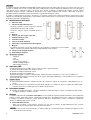
DS80MM1E-001C
DC600
DC600/BR
Contatto magnetico mini
bianco o marrone
White or brown mini magnetic
contact
Weißer oder brauner Mini-
Magnetkontakt
Contact magnétique mini
blanc ou marron
Manuale d’uso, installazione e programmazione
Installation programming and functions manual
Installations
-, programmier- und gebrauchsanleitun
Notice di installation, programmation et utilization
I EN DE FR

2 DS80MM1E-001C
ITALIANO
Il contatto magnetico mini DC600 e DC600/BR controlla l'apertura/chiusura di dispositivi specifici (ed esempio una porta o una
finestra). Il contatto viene fissato sul telaio della porta o della finestra, mentre il magnete di attuazione va fissato sulla porta o
sulla finestra stessa. Quando la porta o la finestra viene aperta, il magnete si allontana dal contatto, facendo scattare
l’interruttore magnetico interno e attivando la trasmissione di un segnale di allarme alla centrale. Il dispositivo ha anche la
possibilità di inviare informazioni relative ad anomalie e segnalazione di batteria scarica.
Il contatto è composto da un coperchio e da una base. Il coperchio contiene tutti i component elettronici, mentre la base viene
utilizzata per l’installazione del dispositivo. Un interruttore tamper interno fornisce una protezione contro tentativi non autorizzati
di apertura o rimozione del dispositivo.
I
Id
de
en
nt
ti
if
fi
ic
ca
az
zi
io
on
ne
e
d
de
el
ll
le
e
p
pa
ar
rt
ti
i
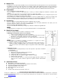
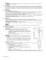
1. Indicatore LED
2. Pulsante di apprendimento/test
-
Premere il pulsante test per trasmettere i dati per
apprendimento da parte della centrale.
-
Premere 1 volta per entrare in modalità test per 3
minuti.
3. Batteria
4. Foro per vite di fissaggio coperchio
5. Predisposizioni per i fori
6. Interruttore tamper
7. Foro per isolante di batteria
8. Indicatori per il posizionamento del magnete
9. Magnete
Posizionare il magnete sul lato del contatto tra i due indicatori. Il contatto può essere installato
diritto o capovolto, per garantire l’allineamento degli indicatori con il magnete.
10. Fori per viti di fissaggio magnete
11. Distanziale per magnete
A
Ac
cc
ce
es
ss
so
or
ri
i
i
in
nc
cl
lu
us
si
i
1 Magnete
2 Viti
2 Tasselli
1 Biadesivo per magnete
2 Viti di montaggio magnete
2 Distanziali per magnete
I
In
nd
di
ic
ca
at
to
or
re
e
L
LE
ED
D
In funzionamento normale, il LED è spento eccetto che nelle seguenti situazioni:
Quando l'interruttore tamper del contatto è aperto
Quando il contatto ha la batteria scarica
Quando il contatto è in modalità Test
Il LED non lampeggia se il tamper e la batteria del contatto funzionano normalmente e non sono in modalità Test.
Il LED lampeggia per indicare la trasmissione di un segnale, lampeggia rapidamente 2 volte quando riceve un segnale di
riconoscimento dalla centrale.
S
Su
up
pe
er
rv
vi
is
si
io
on
ne
e
Con funzionamento normale il contatto trasmette alla centrale un segnale di supervisione ad intervalli da 30 a 50
minuti.
Se è stato attivato il test supervisione nel pannello di controllo e la centrale non riceve il segnale dal contatto entro
un tempo prefissato, la centrale genererà un allarme di supervisione.
I
In
nt
te
er
rr
ru
ut
tt
to
or
re
e
t
ta
am
mp
pe
er
r
Protegge da tentativi di rimozione o apertura dell’involucro. Quando il tamper è aperto, il contatto invia alla centrale
un segnale di allarme e il LED si accende.
B
Ba
at
tt
te
er
ri
ia
a
Il contatto è alimentato da una batteria al litio CR2 3 V ed è in grado di segnalare quando la batteria è scarica. Quando la
batteria è scarica, il dispositivo invia un segnale alla centrale insieme alla normale trasmissione. Il LED si accende quando
il contatto è in allarme con batteria scarica. Quando la batteria è completamente scarica, il contatto non segnala più
allarmi e il LED lampeggia ogni 4 secondi.
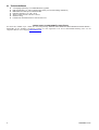
Sostituzione della batteria:
Dopo che la batteria è stata rimossa, premere per 5-6 volte il pulsante di apprendimento/test per scaricare
completamente il dispositivo prima di inserire la nuova batteria.
<
<N
NO
OT
TA
A>
>
Dopo aver inserito una nuova batteria, il contatto verificherà se la batteria funziona correttamente oppure no entro
16 minuti dal suo inserimento.
9
10
11

DS80MM1E-001C 3
M
Mo
od
da
al
li
it
tà
à
T
Te
es
st
t
Il contatto può essere impostato in modalità Test per 3 minuti premendo una volta il pulsante Test sul coperchio anteriore.
In modalità Test, il LED si accende ogni volta che il contatto è attivato. Ogni qualvolta il pulsante Test viene premuto, il
contatto trasmette un segnale alla centrale per un test della portata radio e riattiva nuovamente la modalità Test per 3
minuti. La modalità Test terminerà automaticamente dopo 3 minuti e ritornerà in modalità di funzionamento normale.
P
Pr
re
ep
pa
ar
ra
az
zi
io
on
ne
e
Passo 1: Rimuovere l’isolante di batteria
Passo 2: Abilitare la funzione di apprendimento in centrale; per ulteriori dettagli fare riferimento al manuale della
centrale.
Passo 3: Premere il pulsante Test sul contatto per inviare un segnale alla centrale.
Passo 4: Se la centrale riceve correttamente il segnale, risponderà emettendo dei beep. Per completare il processo di
apprendimento, fare riferimento al manuale della centrale.
Passo 5: Dopo che il contatto è stato appreso, impostare la centrale in modalità “Walk Test”, mantenere il contatto nella
posizione desiderata e premere il pulsante Test per verificare che si trovi all’interno della portata radio della centrale.
Passo 6: Una volta verificata la corretta posizione del contatto, procedere con l’installazione.
I
In
ns
st
ta
al
ll
la
az
zi
io
on
ne
e
Passo 1: Montare il contatto utilizzando una delle modalità descritte di seguito.
Passo 2: Montare il magnete sulla parte più in movimento (come una porta) utilizzando le viti fornite (l’uso del
biadesivo va previsto solo nei casi in cui non è possibile forare).
Allineare il magnete agli indicatori del contatto.
Se necessario, utilizzare il distanziale per magnete per allinearlo correttamente agli indicatori.
<
<N
NO
OT
TA
A>
>
Con porta chiusa, il magnete deve essere ad una distanza inferiore a 15 mm dal rilevatore.
M
Mo
od
da
al
li
it
tà
à
d
di
i
m
mo
on
nt
ta
ag
gg
gi
io
o
Esistono due modi per montare il contatto: con biadesivo o con viti.
Montaggio con biadesivo (solo in casi eccezionali)
I. Pulire la superficie utilizzando uno sgrassatore idoneo.
II. In base al lato di montaggio, rimuovere la pellicola di protezione da uno dei lati
del biadesivo e farlo aderire saldamente al retro del dispositivo.
III. Rimuovere l’altra pellicola di protezione e far aderire saldamente il contatto nella
posizione desiderata.
<
<N
NO
OT
TA
A>
>
Non utilizzare la modalità di montaggio con biadesivo su superfici con vernice
scrostata o crepata, o su superfici irregolari.
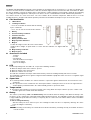
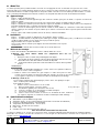
Installare il contatto sull’oggetto fermo (come il telaio di una porta o di una finestra) e
montare il magnete sull'oggetto mobile (come una porta o una finestra). Verificare
con cura che non sia stato smarrito il cappuccio in gomma montato sull’interruttore
tamper.
Montaggio con viti
La base presenta due predisposizioni per i fori, dove la plastica è più sottile, da utilizzare
per il montaggio.
Per montare il contatto:
I. Rimuovere il coperchio svitando le viti di sicurezza.
II. Rompere la predisposizione sulla base.
III. Utilizzando la dima per i fori, praticare i due fori sul muro.
IV. Inserire i tasselli se si esegue il fissaggio su intonaco o mattoni.
V. Avvitare la base ai tasselli.
VI. Fissare il coperchio sulla base e serrare le viti di fissaggio coperchio. Verificare con
cura che non sia stato smarrito il cappuccio in gomma montato sull’interruttore
tamper
S
Sp
pe
ec
ci
if
fi
ic
ch
he
e
t
te
ec
cn
ni
ic
ch
he
e
Alimentazione: 1 batteria litio 3V tipo CR2
Autonomia batterie: 10 anni (valore tipico, può variare in base all’uso)
Frequenza radio bidirezionale: 868.6375 MHz
Temperatura operativa: -10°C to +45°C
Dimensioni: 85 mm x 25 mm x 20 mm
Peso: 100g
Conforme alla norma EN 50131 Grado 2, ClasseⅡ
DICHIARAZIONE DI CONFORMITÀ UE SEMPLIFICATA
Il fabbricante, URMET S.p.A., dichiara che il tipo di apparecchiatura radio: CONTATTO MAGNETICO MINI DC600 – DC600/BR
è conforme alla direttiva 2014/53/UE. Il testo completo della dichiarazione di conformità UE è disponibile al seguente indirizzo
Internet: www.elkron.com
Porta /
Finestra
Predisposizioni
Telaio

4 DS80MM1E-001C
ENGLISH
The DC600 and DC600/BR mini magnetic contact monitors the opening/closing of specific devices (e.g. door or a window). The
contact is fixed onto the door or window frame, while the actuation magnet must be fixed onto the door or window itself. When
the door or window is opened, the magnet moves away from the contact making the inner magnetic switch trip and activating
the sending of an alarm signal to the control panel. The device can also send information on faults and flat battery indications.
The contact consists of a cover and a base. The cover contains all the electronic components, while the base is used for
installing the device. A tamper switch inside provides protection from unauthorised attempts to open or remove the device.
P
Pa
ar
rt
t
i
id
de
en
nt
ti
if
fi
ic
ca
at
ti
io
on
n
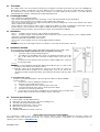
1. LED indicator
2. Learning/test button
-
Press the test button to transmit data for learning
by the control unit.
-
Press once to enter Test mode for three minutes.
3. Battery
4. Cover Fastening screw hole
5. Provision for holes
6. Tamper switch
7. Battery insulation hole
8. Magnet position indicators
9. Magnet
Position the magnet on the side of the contact between the two indicators. The contact may be
installed either straight or upside down to ensure that the indicators are aligned with the
magnet.
10. Magnet fixing screw hole
11. Magnet spacer
A
Ac
cc
ce
es
ss
so
or
ri
ie
es
s
i
in
nc
cl
lu
ud
de
ed
d
1 magnet
2 screws
2 anchor bolts
1 two-sided adhesive for magnet
2 screws for magnet
2 spacers for magnet
L
LE
ED
D
In normal operating mode, the LED is off, except for the following situations:
When the tamper switch of the contact is opened
When the battery of the contact is flat
When the contact is in Test mode
The LED does not blink if the tamper switch and the battery contact are working normally and not in Test mode.
The LED blinks to indicate that a signal is being transmitted and blinks rapidly twice when it receives a recognition signal
from the control unit.
S
Su
up
pe
er
rv
vi
is
si
io
on
n
In normal operation conditions, the contact transmits a supervision signal at intervals from 30 to 50 minutes to the
control unit.
If the supervision test was activated on the control panel and the control panel does not receive the signal from the
contact within a predetermined time, the control unit will generate a supervision alarm.
T
Ta
am
mp
pe
er
r
s
sw
wi
it
tc
ch
h
This protects from attempts to removal or opening of the casing. When the tamper switch is open, the contact sends
an alarm signal to the control unit and the LED is lit.
B
Ba
at
tt
te
er
ry
y
The contact is powered by a CR2 3 V lithium battery and can indicate when the battery is flat. When the battery is flat,
the device sends a signal to the control unit together with normal transmission. The LED lights up when the contact alarm
is tripped with battery flat. When the battery is completely flat, the contact does not indicate alarms and the LED blinks
every 4 seconds.
How to change the battery:
After the battery has been removed, press the learning/test button 5-6 times to completely discharge the device
before inserting the new battery.
<
<N
NO
OT
TE
E>
>
After inserting a new battery, the contact will check whether the battery is working correctly or not within 16 minutes
from its insertion.
9
10
11

DS80MM1E-001C 5
T
Te
es
st
t
m
mo
od
de
e
The contact can be set to Test mode for 3 minutes by pressing the Test button on the front cover once. The LED lights up
whenever the contact is activated in Test mode. Whenever the Test button is pressed, the contact transmits a signal to
the control unit to test the wireless range and re-activates Test mode again for three minutes. Test mode will end
automatically after 3 minutes and will return to normal operating mode.
L
Le
ea
ar
rn
ni
in
ng
g
p
pr
ro
oc
ce
ed
du
ur
re
e
Step 1: Remove the battery insulation.
Step 2: Start the learning function on the control unit; see the control unit manual for more information.
Step 3: Press the Test button on the contact to send a signal to the control unit.
Step 4: If the control unit receives the signal correctly will respond by emitting beeps. Refer to the manual of the control
unit to complete the learning process.
Step 5: After the contact has been learnt, set the control unit to "Walk Test" mode, by holding the contact in the desired
position and press the Test button to check that it is within the wireless range of the control unit.
Step 6: After having checked the correct position of contact, proceed with the installation.
I
In
ns
st
ta
al
ll
la
at
ti
io
on
n
Step 1: Install the contact using one of the methods described below.
Step 2: Install the magnet on the part with the most movement (such as a door) using the screws supplied (double-
sided tape is provided only if drilling is not possible).
Align the magnet with the indicators of the contact.
If necessary, use the magnet spacer to correctly align it with the indicators.
<
<N
NO
OT
TE
E>
>
With the door closed, the magnet must be at a distance of less than 15 mm from the detector.
I
In
ns
st
ta
al
ll
la
at
ti
io
on
n
m
me
et
th
ho
od
d
There are two ways to install the contact: with double-sided adhesive tape or with screws.
Installation with double-sided adhesive tape (exceptional cases only)
I. Clean the surface using a suitable degreaser.
II. According to the installation side, remove the protective film from one of the
sides of the double-sided tape and make it adhere firmly to the back of the
device.
III. Remove the other protective film and make it adhere tightly to the contact in
the desired position.
<
<N
NO
OT
TE
E>
>
Do not use the installation method with double-sided adhesive tape on surfaces with
peeling or cracked paint or on uneven surfaces.
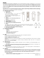
Install the contact on the part which does not move (as the frame of a door or a
window) and install the magnet on the moving object (such as the door or the
window). Carefully check that the rubber cap mounted on the tamper switch is still in
place.
Installation with screws
The base is provided with provisions where the plastic is thinner to allow installation.
To fit the contact:
I. Remove the cover by undoing the retaining screws.
II. Break the areas provided on the base.
III. Using a template for the holes, make the holes in the wall.
IV. Insert the anchor bolts if the device is fixed to plaster or bricks.
V. Screw the base into the anchor bolts.
VI. Secure the cover to the base and tighten the cover fixing screws. Carefully check
that the rubber cap mounted on the tamper switch is still in place.
T
Te
ec
ch
hn
ni
ic
ca
al
l
s
sp
pe
ec
ci
if
fi
ic
ca
at
ti
io
on
ns
s
Power supply: 1 3V CR2 lithium battery
Battery life: 10 years (typical value, can vary according to use)
Two-way radio frequency 868.6375 MHz
Working temperature range -10°C to +45°C
Dimensions: 85 mm x 25 mm x 20 mm
Weight: 100g
Compliant with EN 50131 Grade 2, ClassⅡ
SIMPLIFIED EU DECLARATION OF CONFORMITY
The manufacturer, URMET S.p.A., hereby declares that the wireless device: MINI MAGNETIC CONTACT DC600 and
DC600/BR complies with Directive 2014/53/EU. The complete EU Declaration of Conformity can be downloaded from the
following Internet address: www.elkron.com.
Door /
Window
Provisions
Frame

6 DS80MM1E-001C
DEUTSCH
Der Mini-Magnetkontakt DC600 und DC600/BR steuert das Öffnen/Schließen bestimmter Vorrichtungen (z. B. einer Tür oder
eines Fensters). Der Kontakt wird am Rahmen der Tür oder des Fensters befestigt, währen der Betätigungsmagnet auf der Tür
oder dem Fenster angebracht wird. Wenn die Tür oder das Fenster geöffnet werden, entfernt sich der Magnet von dem Kontakt,
so dass der innere Magnetschalter ausgelöst und die Übertragung eines Alarmsignals an das Steuergerät aktiviert wird. Es
besteht auch die Möglichkeit, mit der Vorrichtung Informationen in Bezug auf Störungen und den Hinweis auf die entladene
Batterie zu versenden.
Der Kontakt setzt sich aus einer Abdeckung und einer Basis zusammen. Die Abdeckung enthält alle elektronischen Bauteile,
während die Basis zur Installation der Vorrichtung verwendet wird. Ein interner Tamper-Schalter liefert einen Schutz gegen
unbefugte Versuche des Öffnens oder Entfernens der Vorrichtung.
I
Id
de
en
nt
ti
if
fi
iz
zi
ie
er
ru
un
ng
g
d
de
er
r
T
Te
ei
il
le
e
1. LED-Anzeige
2. Einlern-/Test-Taste
-
Die Test-Taste betätigen, um die Daten zum
Einlernen in das Steuergerät zu übertragen.
-
Einmal betätigen, um 3 Minuten lang in den Test-
Modus zu gelangen.
3. Batterie
4. Bohrung für die Befestigungsschraube des
Deckels
5. Auslegung für die Bohrungen
6. Tamper-Schalter
7. Bohrung für Batterieisolierung
8. Kennzeichnungen für die Magnetpositionierung
9. Magnet
Den Magnet auf der Seite des Kontakts zwischen den beiden Kennzeichnungen positionieren.
Der Kontakt kann gerade oder umgekehrt installiert werden, um die Ausrichtung der
Kennzeichnungen mit dem Magneten zu garantieren.
10. Bohrungen für Befestigungsschrauben des Magneten
11. Abstandhalter für Magneten
E
En
nt
th
ha
al
lt
te
en
ne
es
s
Z
Zu
ub
be
eh
hö
ör
r
1 Magnet
2 Schrauben
2 Dübel
1 doppelseitiges Klebeband für Magneten
2 Magnet-Befestigungsschrauben
2 Abstandhalter für Magneten
L
LE
ED
D
Bei Normalbetrieb ist die LED-Anzeige ausgeschaltet, außer in den folgenden Situationen:
Wenn der Tamper-Schalter des Kontakts geöffnet ist
Wenn die Batterie des Kontakts leer ist
Wenn der Kontakt sich im Test-Modus befindet
Die LED blinkt nicht, wenn der Tamper und die Batterie des Kontakts normal funktionieren und sich nicht im Test-Modus
befinden.
Die LED blinkt, um die Übertragung eines Signals anzuzeigen und blinkt zwei Mal schnell, wenn sie ein Signal des
Erkennens vom Steuergerät empfängt.
Ü
Üb
be
er
rw
wa
ac
ch
hu
un
ng
g
Bei Normalbetrieb überträgt der Kontakt in Abständen von 30 bis 50 Minuten ein Überwachungssignal an das
Steuergerät.
Wurde im Bedienfeld der Überwachungstest aktiviert und das Steuergerät erhält innerhalb einer festgelegten Zeit
kein Signal vom Kontakt, löst das Steuergerät einen Überwachungsalarm aus.
T
Ta
am
mp
pe
er
r-
-S
Sc
ch
ha
al
lt
te
er
r
Schützt vor Versuchen des Entfernens oder Öffnens des Gehäuses. Ist der Tamper geöffnet, sendet der Kontakt ein
Alarmsignal an das Steuergerät und die LED schaltet sich ein.
B
Ba
at
tt
te
er
ri
ie
e
Der Kontakt wird von einer Lithium-Batterie CR2 mit 3 V gespeist und ist in der Lage, die entladene Batterie anzuzeigen.
Bei entladener Batterie sendet die Vorrichtung zusammen mit der normalen Übertragung ein Signal an das Steuergerät.
Die LED schaltet sich ein, wenn der Kontakt sich bei entladener Batterie im Alarmzustand befindet. Ist die Batterie
vollständig entladen, signalisiert der Kontakt keine Alarme mehr und die LED blinkt alle 4 Sekunden.
Ersetzen der Batterie:
Nachdem die Batterie entfernt wurde, 5-6 Mal die Einlern-/Test-Taste betätigen, um die Vorrichtung vollkommen zu
entladen, bevor die neue Batterie eingelegt wird.
9
10
11

DS80MM1E-001C 7
<
<H
HI
IN
NW
WE
EI
IS
S>
>
Nachdem eine neue Batterie eingelegt wurde, prüft der Kontakt innerhalb von 16 Minuten nach dem Einlegen, ob
die Batterie korrekt funktioniert.
T
Te
es
st
t-
-M
Mo
od
du
us
s
Der Kontakt kann für 3 Minuten in den Test-Modus gestellt werden, indem die Test-Taste auf der vorderen Abdeckung
einmal betätigt wird. Im Test-Modus schaltet sich die LED bei jedem Aktivieren des Kontakts ein. Bei jedem Betätigen der
Test-Taste überträgt der Kontakt ein Signal für einen Test der Funkreichweite an das Steuergerät und aktiviert erneut 3
Minuten lang den Test-Modus. Der Test-Modus endet nach 3 Minuten automatisch und es erfolgt die Rückkehr auf
Normalbetrieb.
V
Vo
or
rb
be
er
re
ei
it
tu
un
ng
g
Schritt 1: Die Batterieisolierung entfernen
Schritt 2: Die Einlernfunktion im Steuergerät aktivieren. Wegen weiterer Einzelheiten siehe Handbuch des Steuergeräts.
Schritt 3: Die Test-Taste auf dem Kontakt betätigen, um ein Signal an das Steuergerät zu senden.
Schritt 4: Erhält das Steuergerät das Signal korrekt, reagiert es durch Ausgabe von Pfeiftönen. Zum Abschließen des
Einlernvorgangs auf das Handbuch des Steuergeräts Bezug nehmen.
Schritt 5: Nachdem der Kontakt eingelernt wurde, das Steuergerät in den Modus "Walk Test" bringen, den Kontakt in der
gewünschten Position halten und die Test-Taste betätigen, um zu überprüfen, ob diese sich innerhalb der
Funkreichweite des Steuergeräts befindet.
Schritt 6: Sobald die korrekte Position des Kontakts geprüft wurde, die Installation vornehmen.
I
In
ns
st
ta
al
ll
la
at
ti
io
on
n
Schritt 1: Den Kontakt anhand einer der im Anschluss beschriebenen Vorgehensweisen montieren.
Schritt 2: Den Magneten auf dem am meisten bewegten Teil (wie einer Tür) montieren und dazu die im Lieferumfang
enthaltenen Schrauben verwenden (die Verwendung von doppelseitigem Klebeband ist nur in den Fällen vorgesehen, in
denen Bohrungen nicht möglich sind).
Den Magneten mit den Kennzeichnungen des Kontakts ausrichten.
Wenn erforderlich den Abstandhalter für Magneten verwenden, um diesen korrekt an den Kennzeichnungen
auszurichten.
<
<H
HI
IN
NW
WE
EI
IS
S>
>
Bei geschlossener Tür muss der Magnet sich in einem Abstand von weniger als 15 mm vom Detektor befinden.
M
Mo
on
nt
ta
ag
ge
eb
be
ed
di
in
ng
gu
un
ng
ge
en
n
Der Kontakt kann auf zwei Arten montiert werden: mit doppelseitigem Klebeband
oder mit Schrauben.
Montage mit doppelseitigem Klebeband (nur in Ausnahmefällen)
I. Die Oberfläche unter Verwendung eines geeigneten Fettlösers reinigen.
II. Abhängig von der Montageseite die Schutzfolie von einer der Seiten
des doppelten Klebebands entfernen und fest an der Rückseite der
Vorrichtung anbringen.
III. Die andere Schutzfolie entfernen und fest am Kontakt in der
gewünschten Position anbringen.
<
<H
HI
IN
NW
WE
EI
IS
S>
>
Die Montageart mit doppelseitigem Klebeband nicht auf Oberflächen mit
abblätterndem oder rissigem Lack oder auf unregelmäßigen Oberflächen
verwenden.
Den Kontakt auf dem stillstehenden Objekt (wie dem Rahmen einer Tür oder
eines Fensters) installieren und den Magneten auf dem beweglichen Objekt
(wie einer Tür oder einem Fenster) montieren. Genau überprüfen, ob die auf
dem Tamper-Schalter montierte Gummikappe nicht verloren gegangen ist.
Montage mit Schrauben
Die Basis weist dort, wo der Kunststoff dünner ist, Auslegungen für die
Bohrungen auf, die für die Montage zu verwenden sind.
Zur Montage des Kontakts:
I. Die Abdeckung durch Lösen der Sicherheitsschrauben entfernen.
II. Den Bohrpunkt auf der Basis durchbrechen.
III. Unter Verwendung der Bohrschablone die beiden Bohrungen an der
Wand anbringen.
IV. Die Dübel einsetzen, wenn die Befestigung auf Verputz oder Ziegel
erfolgt.
V. Die Basis an den Dübeln verschrauben.
VI. Die Abdeckung an der Basis anbringen und die Befestigungsschrauben der Abdeckung anziehen. Genau
überprüfen, ob die auf dem Tamper-Schalter montierte Gummikappe nicht verloren gegangen ist
Tür /
Fenster
Rahmen
Bohrauslegungen

8 DS80MM1E-001C
T
Te
ec
ch
hn
ni
is
sc
ch
he
e
D
Da
at
te
en
n
Versorgungsspannung: 1 3V-Lithium-Batterie Typ CR2
Batterieautonomie: 10 Jahre (normaler Wert, kann je nach Verwendung schwanken)
Bidirektionale Funkfrequenz: 868.6375 MHz
Betriebstemperatur: -10°C bis +45°C
Abmessungen: 85 mm x 25 mm x 20 mm
Gewicht: 100 g
Konform mit der Norm EN 50131, Grad 2, KlasseⅡ
VEREINFACHTE EU-KONFORMITÄTSERKLÄRUNG
Der Hersteller, URMET S.p.A., erklärt, dass der Funkgerätetyp: WEIßER ODER BRAUNER MINI-MAGNETKONTAKT DC600 –
DC600/BR mit der Richtlinie 2014/53/EU konform ist. Der ungekürzte Text der EU-Konformitätserklärung steht auf der
folgenden Website zur Verfügung: www.elkron.com

DS80MM1E-001C 9
FRANÇAIS
Le contact magnétique mini DC600 et DC600/BR commande l’ouverture/fermeture de dispositifs spécifiques (par exemple, une
porte ou une fenêtre). Le contact est fixé sur le cadre de la porte ou de la fenêtre, tandis que son aimant doit être fixé sur la
porte ou la fenêtre elles-mêmes. Lors de l’ouverture de la porte ou de la fenêtre, l’aimant s’éloigne du contact, en déclenchant
l’interrupteur magnétique intérieur et en activant la transmission d’un signal d’alarme vers l’unité de contrôle. Le dispositif est
aussi en mesure d’envoyer des informations relatives à des anomalies et de signaler l’état de pile déchargée.
Le contact se compose d’un cache et d’une base. Le cache abrite tous les composants électroniques, tandis que la base est
utilisée pour l’installation du dispositif. Un interrupteur anti-sabotage (Tamper) intérieur assure la protection contre toute
tentative non autorisée d’ouverture ou de démontage du dispositif.
I
Id
de
en
nt
ti
if
fi
ic
ca
at
ti
io
on
n
d
de
es
s
c
co
om
mp
po
os
sa
an
nt
ts
s
1. LED
2. Bouton d’apprentissage/test
-
Appuyer sur le bouton de test pour transmettre
les données d’apprentissage à l’unité de contrôle.
-
Appuyer une fois pour entrer en mode test
pendant 3 minutes.
3. Pile
4. Trou pour la vis de fixation du couvercle
5. Trous prédécoupés
6. Interrupteur anti-sabotage (Tamper)
7. Trou pour isolant de pile
8. Repères pour la mise en place de l’aimant
9. Aimant
Positionner l’aimant sur le côté du contact, entre les deux repères. Le contact peut être installé
droit ou renversé, pour garantir l’alignement des repères avec l’aimant.
10. Trous pour les vis de fixation de l’aimant
11. Entretoise pour aimant
A
Ac
cc
ce
es
ss
so
oi
ir
re
es
s
i
in
nc
cl
lu
us
s
1 Aimant
2 Vis
2 Chevilles
1 Ruban adhésif double face pour aimant
2 Vis de montage aimant
2 Entretoises pour aimant
L
LE
ED
D
En fonctionnement normal, la LED est éteinte, sauf dans les situations suivantes :
Lorsque l’interrupteur anti-sabotage du contact est ouvert
Lorsque la pile du contact est déchargée
Lorsque le contact est en mode Test
La LED ne clignote pas si l’interrupteur anti-sabotage et la pile du contact fonctionnent normalement et ne sont pas en
mode Test.
La LED clignote pour indiquer la transmission d’un signal; elle clignote rapidement deux fois lors de la réception d’un
signal d’identification en provenance de l’unité de contrôle.
S
Su
up
pe
er
rv
vi
is
si
io
on
n
Pendant le fonctionnement normal, le contact transmet à l’unité de contrôle un signal de supervision à des
intervalles de 30 à 50 minutes.
Si le test de supervision a été activé sur le panneau de commande et que l’unité de contrôle ne reçoit pas de signal
en provenance du contact dans un laps de temps déterminé, elle émettra une alarme de supervision.
I
In
nt
te
er
rr
ru
up
pt
te
eu
ur
r
a
an
nt
ti
i-
-s
sa
ab
bo
ot
ta
ag
ge
e
(
(T
Ta
am
mp
pe
er
r)
)
Il protège contre les tentatives de démontage ou d’ouverture du boîtier. Lorsque le tamper est ouvert, le contact
envoie un signal d’alarme à l’unité de contrôle et la LED s’allume.
P
Pi
il
le
e
Le contact est alimenté par une pile au lithium CR2 3 V et il est en mesure de signaler que la pile est déchargée.
Lorsque la pile est déchargée, le dispositif envoie à l’unité de contrôle un signal en même temps que sa transmission
normale. La LED s’allume lorsque le contact est en état d’alarme pour cause de pile déchargée
.
Lorsque la pile n'est pas
complètement déchargée, le contact ne signale plus d’alarmes et la LED clignote toutes les 4 secondes.
Remplacement de la pile:
Après avoir retiré la pile, appuyer 5-6 fois le bouton d’apprentissage/test pour décharger complètement le dispositif
avant de mettre en place une nouvelle pile.
<
<R
RE
EM
MA
AR
RQ
QU
UE
E>
>
Après avoir mis en place une nouvelle pile, le contact en vérifiera le fonctionnement dans les 16 minutes qui
suivent.
9
10
11

10 DS80MM1E-001C
M
Mo
od
de
e
T
Te
es
st
t
Le contact peut être placé pendant 3 minutes en mode Test en appuyant une fois sur le bouton Test, présent sur le cache
avant. En mode Test, la LED s'allumera chaque fois que le contact sera activé. Chaque fois que le bouton Test est enfoncé, le
contact transmettra à la centrale un signal de test de la portée radio et le mode Test sera réactivé pendant 3 minutes. Le mode
Test se terminera automatiquement au bout de 3 minutes et le dispositif reviendra au mode de fonctionnement normal.
A
Ap
pp
pr
re
en
nt
ti
is
ss
sa
ag
ge
e
Étape 1 : Retirer l’isolant de la pile.
Étape 2 : Habiliter la fonction apprentissage dans l’unité de contrôle; pour plus de détails, se reporter au manuel de
l’unité de contrôle.
Étape 3 : Appuyer sur le bouton Test, présent sur le contact, pour envoyer un signal à l’unité de contrôle.
Étape 4 : Si l’unité de contrôle reçoit correctement le signal, elle répondra en émettant un bip sonore. Pour compléter la
procédure d’apprentissage, se reporter au manuel de l’unité de contrôle.
Étape 5 : Une fois le contact appris, placer l’unité de contrôle en mode “Walk Test”, maintenir le contact dans la position
désirée et appuyer sur le bouton Test pour vérifier que le contact se trouve bien dans le rayon de portée radio de l’unité
de contrôle.
Étape 6 : Après avoir vérifié la position correcte du contact, continuer l’installation.
I
In
ns
st
ta
al
ll
la
at
ti
io
on
n
Étape 1 : Installer le contact en utilisant l’une des méthodes décrites ci-après.
Étape 2 : Installer l’aimant sur la partie la plus mobile (par exemple, le battant d’une porte), en utilisant les vis fournies
(n’utiliser l’adhésif double face que lorsqu’il n’est pas possible de percer).
Aligner l’aimant sur les repères du contact.
Si nécessaire, utiliser l’entretoise pour aligner correctement l’aimant sur les repères.
<
<R
RE
EM
MA
AR
RQ
QU
UE
E>
>
Porte fermée, l’aimant doit se trouver à moins de 15 mm du détecteur
.
Méthode de montage
Il existe deux méthodes d’installation du contact : adhésif double face ou vis.
Montage avec ruban adhésif double face (uniquement dans des cas
exceptionnels)
I. Nettoyer la surface à l’aide d’un produit dégraissant adapté.
II. En fonction du côté de montage, retirer le film de protection d’une des faces du
ruban adhésif et le faire bien adhérer à l’arrière du dispositif.
III. Retirer l'autre film de protection et faire bien adhérer le contact dans la position
désirée.
<
<R
RE
EM
MA
AR
RQ
QU
UE
E>
>
Ne pas utiliser le ruban adhésif double face sur des surfaces à la peinture écaillée ou
fissurée ou sur des surfaces irrégulières.
Installer le contact sur l’élément fixe (par exemple, le cadre d’une porte ou d’une
fenêtre) et placer l’aimant sur l’élément mobile (par exemple, une porte ou une fenêtre). Veiller à
ne pas égarer le capuchon en caoutchouc installé sur l’interrupteur anti-sabotage.
Montage à l'aide de vis
La face arrière comporte deux prédécoupages pour les trous, où le plastique est plus
mince, à utiliser pour le montage.
Pour installer le contact :
I. Retirer le cache, en dévissant les vis de sécurité.
II. Briser le prédécoupage sur la face arrière.
III. En utilisant le gabarit, percer deux trous dans le mur.
IV. Insérer les chevilles en cas de montage sur enduit ou briques.
V. Visser la face arrière dans les chevilles.
VI. Fixer le cache à la face arrière et serrer les vis de fixation du cache. Veiller à ne
pas égarer le capuchon en caoutchouc installé sur l’interrupteur anti-sabotage.
S
Sp
pé
éc
ci
if
fi
ic
ca
at
ti
io
on
ns
s
t
te
ec
ch
hn
ni
iq
qu
ue
es
s
Alimentation : 1 pile au lithium 3V type CR2
Autonomie de pile : 10 ans (valeur nominale pouvant varier en fonction de l’utilisation)
Fréquence radio bidirectionnelle : 868.6375 MHz
Température de fonctionnement : -10°C à +45°C
Dimensions : 85 mm x 25 mm x 20 mm
Poids : 100g
Conforme à la norme EN 50131 Grade 2, ClassⅡ
DÉCLARATION DE CONFORMITÉ UE SIMPLIFIÉE
Le fabricant, URMET S.p.A., déclare que l’équipement radio : CONTACT MAGNÉTIQUE MINI BLANC OU MARRON DC600 –
DC600/BR sont conformes à la Directive 2014/53/UE. Le texte intégral de la Déclaration de conformité UE est disponible sur le
site Web suivant : www.elkron.com
ELKRON
Tel. +39 011.3986711 - Fax +39 011.3986703
www.elkron.com – mail to: [email protected]
MADE IN TAIWAN
Porte /
Fenêtre
Trous prédécoupés
Cadre
-
 1
1
-
 2
2
-
 3
3
-
 4
4
-
 5
5
-
 6
6
-
 7
7
-
 8
8
-
 9
9
-
 10
10


Elkron DC600/BR Guide d'installation
- Taper
- Guide d'installation
- Ce manuel convient également à
dans d''autres langues
- italiano: Elkron DC600/BR Guida d'installazione
- English: Elkron DC600/BR Installation guide
- Deutsch: Elkron DC600/BR Installationsanleitung