Bertazzoni REF24FCIPIXR Guide d'installation
- Taper
- Guide d'installation

Installation guide
Notice d’installation
Guía de instalación
REF18WCPIXL
REF18WCPIXR
REF18FCIPIXL
REF18FCIPIXR
REF18WCPRL
REF18WCPRR
REF18FCIPRL
REF18FCIPRR
REF24RCPIXL
REF24RCPIXR
REF24WCPIXL
REF24WCPIXR
REF24FCIPIXL
REF24FCIPIXR
REF24RCPRL
REF24RCPRR
REF24WCPRL
REF24WCPRR
REF24FCIPRL
REF24FCIPRR
REF30RCPIXL
REF30RCPIXR
REF30FCIPIXL
REF30FCIPIXR
REF30RCPRL
REF30RCPRR
REF30FCIPRL
REF30FCIPRR
REF36RCPIXL
REF36RCPIXR
REF36RCPRL
REF36RCPRR


3
1
1.1
1.2
IMPORTANT INSTRUCTIONS
Important safety instructions.....................................................................................................................................
Children safety................................................................................................................................................................
4
4
4
2
2.1
2.2
2.3
TECHNICAL REQUIREMENTS
Appliance features and installation requiremens................................................................................................
Installation cutout features: panel ready................................................................................................................
Installation cutout features: panel installed..........................................................................................................
4
4
6
7
3
3.1
3.2
3.3
3.4
PREPARING THE INSTALLATION
Transport to installation site and unpacking.........................................................................................................
Electrical and water connection................................................................................................................................
Energy: Alternatives and Home Automation.........................................................................................................
Levelling...........................................................................................................................................................................
8
8
8
9
9
4
4.1
4.2
CUTOUT DIMENSIONS
Cutout dimensions and installation..........................................................................................................................
Flush installation with standard trims....................................................................................................................
10
10
10
5
5.1
5.2
5.3
5.4
5.5
PANELS MOUNTING
Decorative door panel layout......................................................................................................................................
Decorative panel for fridge column..........................................................................................................................
Decorative panels layout for wine column with glass door..............................................................................
Panel dimensions column models...........................................................................................................................
Mounting panels to the door.......................................................................................................................................
11
11
13
14
15
16
6
6.1
6.2
6.3
INSTALLATION
Built-in installation of single appliance...................................................................................................................
Built-in installation of two or more appliances.....................................................................................................
Maximum cabinet depth over panel ready appliance with single door panel.............................................
18
18
18
22
7
7.1
7.2
7.3
7.4
COMPLETING THE INSTALLATION
Anti-tipping safety assembly......................................................................................................................................
Ventilation........................................................................................................................................................................
Post installation control...............................................................................................................................................
Start up.............................................................................................................................................................................
23
23
24
25
25
INDEX
EN

4
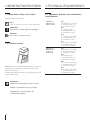
1.1 Important safety instruction
Symbols used in the Guide:
Note
Tips for the correct use of the appliance
Important
Directions to avoid appliance damage
Warning
directions to prevent injury
1.2 Children safety
DANGER: Risk of child entrapment. Before you throw
away your old refrigerator, freezer or wine cellar:
> Take o the doors
> Leave the shelves in place so that children may not
easily climb inside.
Important!
Dimensions in parentheses are in inches.
Weights in parentheses are in pounds.
Temperatures in parentheses are
in Fahrenheit degrees.
1. IMPORTANT INSTRUCTIONS
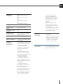
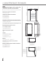
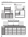
Appliance
dimensions
panel ready
18”
w: 456 mm (17 15/16”)
h: 2120 mm (83 1/2”)
d: 615 mm (24 1/4”)
24”
w: 609 mm (24”)
h: 2120 mm (83 1/2”)
d: 615 mm (24 1/4”)
30”
w: 761 mm (29 15/16”)
h: 2120 mm (83 1/2”)
d: 615 mm (24 1/4”)
36”
w: 913 mm (35 15/16”)
h: 2120 mm (83 1/2”)
d: 615 mm (24 1/4”)
Appliance
dimensions
stainless
steel clad
18”
w: 456 mm (17 15/16”)
h: 2120 mm (83 1/2”)
d: 620 mm (24 3/8”)
24”
w: 609 mm (24”)
h: 2120 mm (83 1/2”)
d: 620 mm (24 3/8”)
30”
w: 761 mm (29 15/16”)
h: 2120 mm (83 1/2”)
d: 620 mm (24 3/8”)
36”
w: 913 mm (35 15/16”)
h: 2120 mm (83 1/2”)
d: 620 mm (24 3/8”)
2.1 Appliance features and installation
requirements
2. TECHNICAL REQUIREMENTS

5
Weight with
packaging
18”
up to 150 kg (331 lb)
24”
up to 170 kg (375 lb)
30”
up to 190 kg (419 lb)
36”
up to 200 kg (441 lb)
Voltage AC 110 - 120V 60Hz
Power supply
cable
90° Nema 5-15P
Dedicated circuit
breaker
15A
Potable water
supply pressure
from 0.05 MPa to 0.5 MPa
(0.5 Bar - 5 Bar)
PSI measurement 7.25psi - 72.5psi
Water connection 3/4” NPT (1/4” elbow adap-
ter included)
Provided
installation
accessories
- Anti tipping kit Z310113
(in all columns panel ready
and panel installed)
- Joining strip, white
Z310057 (in all columns
panel ready and panel
installed)
- Lateral mounting clips
(10 pieces white) Z310129
(in all columns panel ready
and panel installed)
- Customized panels
mounting kit, fridge and
freezer Z310272 (only in
fridge and freezer columns
panel ready)
- Customized panels
mounting kit, wine cellar
Z310273 (only in wine co-
lumns panel ready)
- Central connection kit , for
panel ready models com-
bined installation Z310293
(only in freezer and wine
columns panel ready)
EN
- Central connection kit,
for panel installed mo-
dels combined installation
Z310287 (only in freezer
and wine columns panel
installed)
- Water connection kit
Z310300 (only in freezer
columns panel ready and
panel installed)
- 4 mm (1/8”) allen wrench
(in all columns panel ready
and panel installed)
Additional
equipment
necessary
- Phillips head screwdriver
- wood drill
- 2.5 mm (1/8”) bit for wood
- 8 mm (3/8”) bit for walls
- 10 mm (3/8”) bit for walls
- 17 mm (11/16”) wrench
- 19 mm (3/4”) wrench
Others provided
accessories
- Cleaning kit Z310284
(in all columns panel ready
and panel installed)

6
2. TECHNICAL REQUIREMENTS
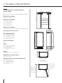
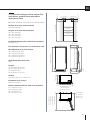
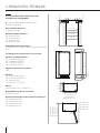
2.2 Installation cutout features:
panel ready
A - area to be left clear for the anti-tipping brackets
Minimum cutout Height
2130 mm (83 7/8”)
Minimum cutout Width
36”: 914 mm (36”)
30”: 762 mm (30”)
24”: 610 mm (24”)
18”: 457 mm (18”)
Minimum cutout Depth
615 mm (24 1/4”) + panel thickness for flush install
Door hinges do not lock at 90°
Door Swing Clearance
36”: 1489 mm (58 5/8”)
30”: 1338 mm (52 5/8”)
24”: 1187 mm (46 3/4”)
18: 1036 mm (40 3/4”)
Door Opening Angle
100°
Width
36”: 913 mm (35 15/16”)
30”: 913 mm (29 15/16”)
24”: 609 mm (24”)
18”: 456 mm (17 15/16”)
Height
2120 mm (83 1/2”) + 25 mm (1”)
Depth with door (without panel)
615 mm (24 1/4”)
Minimum distance from the wall (hinge side)
36”: 158 mm (6 1/4”)
30”: 132 mm (5 1/4”)
24”: 108 mm (4 1/4””)
18”: 82 mm (3 1/4”)
233 (9
¼”
)
+ 25 (1”)
615 (24 ¼”)
565 (22 ¼” )
1808 (71 ¼” )
231 (9
⅛”
) +
25 (1”)
505 (19 ¾”)
2120 (83 ½”) +25 (1”)
min 2130 (83 ⅞”)
A A
127 mm (5") 127 mm (5")
82 mm (3 1/2")
82 mm (3 1/2")
36":914 (36”)
18": 457 (18”)
24": 610 (24”)
30": 762 (30”)
100°
36": 1489 (58 ⅝")
30": 1338 (52 ⅝")
24": 1187 (46 ¾")
18": 1036 (40
¾
")
565 (22 ¼")
615 (24 ¼")
36": 913 (35
15⁄ 16
")
30": 761 (29
15⁄ 16
")
24": 609 (24")
18": 456 (17
15⁄ 16
")
36": 158 (6 ¼")
30": 132 (5 ¼" )
24": 108 (4 ¼")
18": 82 (3 ¼")
100°
36": 1489 (58
⅝")
30": 1338 (52 ⅝")
24": 1187 (46
¾")
18": 1036 (40
¾
")
565 (22 ¼")
615 (24 ¼")
36": 913 (35
15⁄ 16
")
30": 761 (29
15⁄ 16
")
24": 609 (24")
18": 456 (17
15⁄ 16
")
36": 158 (6 ¼")
30": 132 (5 ¼" )
24": 108 (4 ¼")
18": 82 (3 ¼")
233 (9
¼”
)
+ 25 (1”)
min 2130 (83 ⅞”)
A A
140 (5 ½”) 140 (5 ½”)
100 (4”)
100 (4”)
S899 / FI36: 914 (36”)
S449 / FI18: 457 (18”)
S599 / FI24: 610 (24”)
S749 / FI30: 762 (30”)
615 (24 ¼”)
565 (22 ¼” )
1808 (71 ¼” )
231 (9
⅛”
) +
25 (1”)
505 (19 ¾”)
2120 (83 ½”) +25 (1”)

7
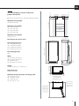
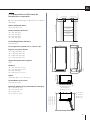
2.3 Installation cutout features:
panel installed
A - area to be left clear for the anti-tipping brackets
Minimum Cutout Height
2130 mm (83 7/8”)
Minimum Cutout Width
36”: 914 mm (36”)
30”: 762 mm (30”)
24”: 610 mm (24”)
18”: 457 mm (18”)
Minimum Cutout Depth
635 mm (25”)
Door hinges do not lock at 90°
Door Swing Clearance
36”: 1487 mm (58 1/2”)
30”: 1336 mm (52 5/8”)
24”: 1185 mm (46 5/8”)
18”: 1034 mm (40 3/4”)
Door Opening Angle
100°
Width
36”: 913 mm (35 15/16”)
30”: 761 mm (29 15/16”)
24”: 609 mm (24”)
18”: 456 mm (17 15/16”)
Height
2120 mm (83 1/2”) + 25 mm (1”)
Depth with door
620 mm (24 3/8”)
Minimum distance from the wall (hinge side)
36”: 139 mm (5 1/2””)
30”: 103 mm (4 1/8”)
24”: 89 mm (25”)
18”: 63 mm (2 1/2”)
100°
36": 1487 (58 ½”)
30": 1336 (52 ⅝”)
24": 1185 (46 ⅝”)
18": 1034 (40 ¾’’)
565 (22 ¼”)
620 (24 ⅜”)
36": 913 m m ( 35
15⁄ 16
")
30": 761 m m ( 29
15⁄ 16
")
24": 609 m m ( 24")
18": 456 m m ( 17
15⁄ 16
")
55 (3 ⅛”)
58 (2 ¼”)
36": 139 (5 ½”)
30": 103 (4 ⅛”)
24": 89 (3 ½”)
18": 63 (2 ½”)
A A
E W E W
140 (5 ½”) 140 (5 ½”)
100 (4”)
100 (4”)
KS899: 900 (35 ½”)
KS599: 600 (23 ¾”)
KS749: 750 (29 ⅝”)
620 (24 ⅜” )
565 (22 ¼” )
0F
672 (26 ½”)
1904 (75”)
146 (5
¾”)
+ 25(1”
)
KS449: 450 (17 ¾”)
2120 (83 ½”) +25 (1”)
2120 (83 ½”) +25 (1”)
233 (9
¼”
)
+ 25 (1”)
min 2130 (83 ⅞”)
A A
127 mm (5") 127 mm (5")
82 mm (3 1/2")
82 mm (3 1/2")
36":914 (36”)
18": 457 (18”)
24": 610 (24”)
30": 762 (30”)
615 (24 ¼”)
565 (22 ¼” )
1808 (71 ¼” )
231 (9
⅛”
) +
25 (1”)
505 (19 ¾”)
2120 (83 ½”) +25 (1”)
100°
36": 1487 (58 ½”)
30": 1336 (52 ⅝”)
24": 1185 (46 ⅝”)
18": 1034 (40 ¾’’)
565 (22 ¼”)
620 (24 ⅜”)
36": 913 m m ( 35
15⁄ 16
")
30": 761 m m ( 29
15⁄ 16
")
24": 609 m m ( 24")
18": 456 m m ( 17
15⁄ 16
")
55 (3 ⅛”)
58 (2 ¼”)
36": 139 (5 ½”)
30": 103 (4 ⅛”)
24": 89 (3 ½”)
18": 63 (2 ½”)
EN

8
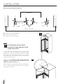
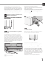
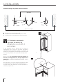
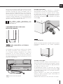
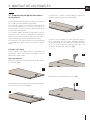
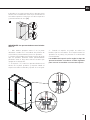
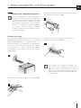
3.1 Transport to installation site
and unpacking
The appliance is very heavy.
Take maximum care during handling
to avoid injury.
The appliance should always be
transported in an erect position.
Avoid at all costs leaning it on its front
side.
Since this is a large and heavy appliance, before trans-
porting the appliance, check the access to the loca-
tion where it will be installed (door size, maneuvering
space in stairwells, etc.).
The appliance is attached to the base of the packaging
(pallet) through four bolts which can be removed us-
ing a 19 mm (3/4”) wrench.
It is recommended to use a manual transporting de-
vice to move the appliance to the installation site, and
only at this point to remove the base of the packaging.
The appliance should always be transported in an
erect position.
If this is not possible, transport the appliance laying
on its rear side.
Once at the installation site, the appliance, which is
equipped with four wheels, can be taken o the pallet
and positioned in the installation area.
Operate as follows:
> Take o the four bolts securing [ 1 ] the appliance to
the pallet by means of a 19 mm (3/4”) wrench or socket.
> Remove the fixing brackets [ 3 ] and [ 4 ] .
> To release the front fixing bracket [ 3 ] , unscrew the
rear wheel adjusting bolt [ 2 ] by means of a 13 mm
(1/2”) wrench or socket. Avoid straining this bolt at its
stop points one way or the other so as to not damage
the rear leveling system.
Ensure the front leveling legs are retracted so that all
4 wheels are able to contact the floor for easiest ma-
neuvering.
> From the back of the unit and by means of a suit-
able, high duty hand trolley, take o the appliance and
place it on the floor.
Be very careful to avoid any damage to floors. Delicate
floors should be protected with plywood, hard card-
board or similar material panels.
3. PREPARING THE INSTALLATION
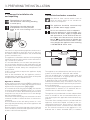
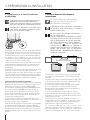
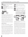
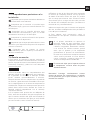
3.2 Electrical and water connection
The Built-in filter cannot make it safe to
drink any water which is not suitable for
human consumption.
The appliance should be connected only
to a potable water supply system.
Do not use extension cords or adapters.
Once the appliance is fully installed, con-
nected to the water supply (if applicable)
and operational, in the event that the wa-
ter supply must be turned off, (touch the
button
Ice Maker
Water Filter
Water System Purge
on control panel to disable the
ice maker) before the main water is shut
off to prevent the appliance from entering
a ‘NO WATER IN’ alarm state.
The appliances are delivered from the factory for op-
eration at 110V-120V AC - 60Hz (US and Canada).
They are provided with a suitable supply cable and
plug to be connected to an appropriate 15A socket
providing an eective grounding.
A dedicated 15A circuit breaker should also be in-
stalled and should be easily accessible so that it can
be easily switched o before performing any installa-
tion or maintenance.
To connect to the water supply system (for appliances
equipped with ice makers) a 1/4” waterline with ac-
cessible shut-o valve must be supplied.
The appliance is provided with a water adapter elbow
which is suitable for the recommended water pres-
sure and complies the applicable food and water reg-
ulations.
The water filter cartridge, which is provided with the
appliance, should be installed according to the ac-
companying instructions. Please refer to water filter
installation instructions contained in the water filter
kit. The solenoid connection on the appliance is 3/4”
diameter but is metric threaded (NPT). A standard
E
E
E
E
E
W
W
W
W
W
E
W
1
4
1
2
3
EW
E W
EW
E W
ELECTICAL & WATER
CONNECTION

9
garden hose threaded connector such as a braided
stainless hose found at typical hardware stores will
strip or damage the solenoid threads. It is recom-
mended to use only the supplied 1/4” quick connect
elbow adapter for connecting a 1/4” copper or poly-
ethylene source water line to the appliance.
Do not use extension cords and/or mul-
tiple adapters for the power supply con-
nection.
ELECTRICAL AND WATER SUPPLY
BEHIND THE UNIT
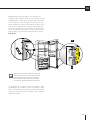
3.3 Energy: Alternatives and Home Auto-
mation
If energy is supplied through an alternative en-
ergy power source (solar, geothermal, etc..) or
if home automation systems are installed with
carrier signals in the power lines, it may be nec-
essary to install an isolation transformer (not
supplied) to prevent interference with the appli-
ance’s electronics.
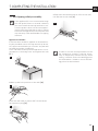
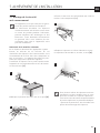
fig.1 Back of appliance
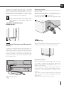
Operate as follows:
> Unwind the electric cable and connect it directly to
the wall socket.
> Make sure the appliance is in the Stand-by con-
dition and that all lights are o; should it be not so
press the Unit button to switch it o.
> Connect the water cable behind the appliance [ 1 ].
Water connection
Electrical connection
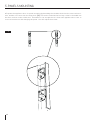
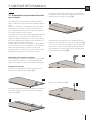
3.4 Levelling
Adjust the appliance level by means of the front
levelling feet and the rear adjustable wheels.
Operate as follows:
> If necessary, remove the bottom plinth or grille
(it is kept in position by magnets), adjust the
height of the levelling feet [ 1 ] by means of a 17
mm (11/16”) wrench.
> Then adjust the height of the rear wheels by
turning the front adjusting bolts [ 2 ] clockwise
(raise) or counter-clockwise as it may be re-
quired.
Take care if using a power driver for this and
lower the clutch to prevent damaging the leveling
mechanism.
> Remount the bottom plinth or grille.
EN
E
W
E
W
1
2
1
2
1

10
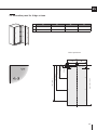
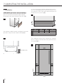
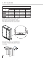
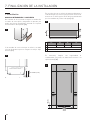
4.1 Cutout dimensions and installation
36”
30”
24”
18”
908 (35 3/4”)914 (36”)
762 (30”)
610 (24”)
457 (18”)
756 (29 3/4”)
451 (17 3/4”)
604 (23 3/4”)
Panel WidthCutout width
Series
4. CUTOUT DIMENSIONS
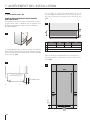
4.2 Flush installation with standard
trims
Cutout dimension for combined installation
A
A
A - KCLITU: Lateral connection Kit (included)
A
B
18” 24” 30” 36”
18” 36”(914mm) 42”(1067mm) 48”(1220mm) 54”(1372mm)
24” 42”(1067mm) 48”(1220mm) 54”(1372mm) 60”(1520mm)
30” 48”(1220mm) 54”(1372mm) 60”(1520mm) 66”(1676mm)
36” 54”(1372mm) 60”(1524mm) 66”(1676mm) 72”(1829mm)
24": 610 (24”)
30": 762 (30”)
36": 914 (36”)
18": 457 (18”)
A
B

11
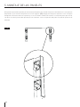
5.1 Decorative door panel layout
The dimensions of the panels are indicated in the
table and drawings on subsequent pages.
Nevertheless, according to the requirements for
aligning with other kitchen structures, the door
panel can be higher than the upper edge of the
refrigerator door.
The panels must be mounted using special bra-
ckets which attach to adjustable devices provided
on the door and drawer and with brackets that
anchor and adjust the panel’s vertical direction.
Brackets and fixing screws are provided with the
appliance and must be applied to the panel as in-
dicated.
Operate as follows:
To prepare the panels to be mounted on the ap-
pliance, follow these steps, working on the back
of the panel.
Door Panel
> Draw a vertical center line on the panel from
top to bottom [ 1 ].
> Starting from the bottom edge of the panel,
mark the positioning of the brackets [ 2 ].
5. PANELS MOUNTING
2
1
> Following the corresponding table, mark the
external and then the internal hole [ 3 ].
> Position the brackets on each set of marks to
make sure they are aligned [ 4 ], if you choose to
drill small pilot holes for the screws pay special
attention to not pass through the panel entirely.
[ 5 ].
> Screw the brackets in place [ 6 ].
6
4
3
5
EN

12
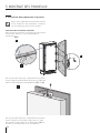
> Prepare the appliance door for panel mounting by threading the shoulder bolts into the recessed recei-
vers and the set screws into the other hole [ 7 ]. Ensure the end with the hex key socket is threaded into
the door and not on the visible end. Thread this in far enough that it is flush with appliance door face so
as not to interferece with hanging the panel. You will adjust these later.
7
5. PANELS MOUNTING

13
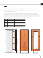
5.2 Decorative panel for fridge column
Holes positions:
36” 30” 24” 18”
A 908 (35 3/4”) 756 (29 3/4”) 604 (23 3/4”) 451 (17 3/4”)
B 418 (16 1/2”) 343 (13 1/2”) 275 (10 7/8”) 200 (7 7/8”)
EN
1
1797 (70 ¾”)
B B
A
34 (1 3⁄8”) 34 (1 3⁄8”)
165 (6 ½”)
1271,5 (50”)
690,5 (27
¼”)
112 (4
3⁄8”)
min 1929 (75
7⁄8”)
6,5 (¼”)
6,5 (
¼”)

14
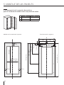
5.3 Decorative panels layout
for wine column with glass door
24” 18”
A 604 (23 3/4”) 451 (17 3/4”)
B 275 (10 7/8”) 200 (7 7/8”)
1
Door window dimensions: Holes positions:
5. PANELS MOUNTING
B B
A
34 (1
3⁄8”
) 34 (1
3⁄8”
)
1797 (70
¾
”)
165 (6
½”
)
1271,5 (50”)
690,5 (27
¼
”)
112 (4
3⁄8”
)
min 1929 (75
7⁄8
”)
6,5 (
¼”
)
6,5 (
¼”
)
1572 (62”)
599: 327 (12
7⁄8”
)
449: 177 (6
7⁄8”)
139 (5
½”
)
139 (5 ½”)
200
(7
7⁄8”)

15
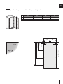
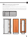
5.4 Panel dimensions column models
Panels with width ranging between 19 mm (3/4 ”) and 28 mm (1 1/8 ”).
Door panels with weight max of 34 kg (75 lb)
Exceeding these weights could void your warranty for any service issues which can be attributed to
overweight panels.
The hinging mechanism on Bertazzoni appliances is considered to be `Zero-clearance`. The door and
drawer widths specified below assume the minimum cutout width is being used and a 3.5mm (1/8”) reveal
is desired around the panels. Adjust your panel dimensions accordingly to your own design criteria consi-
dering your cutout width and your reveal. Minimum reveal / gap should not be less than 1.5mm (1/16”).
SERIES DOOR WIDTH A DOOR GLASS WINDOW WIDTH B
36” 908 (35 3/4”) -
30” 756 (29 3/4”) -
24” 604 (23 3/4”) 327 (12 7/8”)
18” 451 (17 3/4”) 177 (6 7/8”)
EN
2120 (83 7/16") + 25 (1")
min 1929 (75 7⁄8
”
)
max 2027 (79
¾”)
min 100 (3
7⁄8”)
For fridge and freezer columns For wine columns
A B
139
(5 ½”)
139
(5 ½”)
1572 (62”)

16
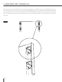
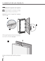
5.5 Mounting panels to the door
Once all brackets and small brackets
have been applied to the panels, you can
begin installing the bottom drawer.
> Hook the panel to the fixing devices starting
from the top aligning brackets [ 6 ].
> At this point, alignment between the panel and
adjacent cabinets can be adjusted using the ali-
gnment brackets and small brackets [ 7 ] and [ 8 ].
> Vertical alignment: tighten or loosen the screw
in the brackets to raise or lower the panel [ 9 ].
5. PANELS MOUNTING
7
9
8
6

17
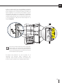
> Depth alignment: working from the inside of
the door, after lifting up the magnetic seal on the
handle side and rotating the plastic covers on
the hinge side, adjust the panel position in the
Z-direction by adjusting the shoulder bolts and
setscrews with the 4mm hex key in conjunction
with each other finally locking each mounting po-
sition in place. [ 10 & 11 ].
Once the front panel has been adjusted,
check that the gasket has been repositioned
correctly to assure the door/drawer are
closing correctly and avoid operational
errors of the unit.
The product handle is not included in the appliace
packaging, but it has to be bought separately. For
handle installation, please refer to the instruction
included in handle’s package.
EN
10
11

18
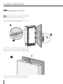
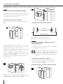
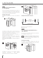
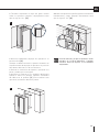
6.1 Built-in installation of
single appliance
For a built-in installation, to cover gaps between
the appliance and the adjacent cabinets, special
side profiles and covering frames are already
factory installed.
Operate as follows:
> Push the appliance into the installation cutout [ 1 ].
> Always mount front panel on door before push-
ing the unit into its final position inside the cutout
or structure.
> Check the levelling of the appliance, adjusting
its feet and wheels to correct it.
> Secure the appliance to the adjacent cabinets by
fixing to these the side profiles factory-installed
on the appliance [ 2 ].
To make this operation easier keep the door open.
> Mount the profiles the trim covers: first insert
them laterally and then push firmly until a “click”
is heard [ 3 ].
6. INSTALLATION
Side profiles mounting:
A plastic connecting brackets
B Profile trim cover
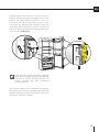
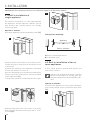
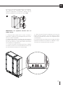
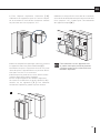
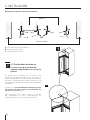
6.2 Built-in installation of two or
more appliances
> The central profile is provide with freezer and
wine cellar columns.
Special side profiles and plastic covering
frames are provided for closing gaps be-
tween the appliance and the adjacent cabi-
nets.
Operate as follows:
> Position the appliances in front of the installation
area, leaving enugh space to operate at their back
[ 1 ].
IMPORTANT: The following instruction for installation apply to all Bertazzoni models.
A
B
B
Appliance
Wall or furniture
1
3
1
2

19
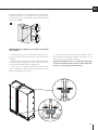
> Access the back of the appliances to mount the
joining brackets: fix one side of the top and lower
brackets to one of the appliances and subsequently
to the other [ 2 ].
IMPORTANT: the appliances must be level with
one another.
1 – Attach both units to each other at the front us-
ing the 5 white plastic brackets to hold the units
together.
2 – Adjust the units in the back, so that the side pan-
els are perfectly parallel to each other. There are
visual cues that will aid with alignment.
3 – The gap ( C ) between the units must be the
same at the back and top. Measure the gap on all
edges and adjust if not equal.
EN
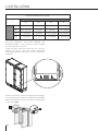
4 – Once the gap is consistent on all edges, secure
the brackets. If the gap between the units is not
even, doors will not align properly.
Gap measurements vary according to the types
of units installed. Please refer to the table be-
low for correct gap measurements.
C
C
A
B
2

20
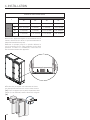
6. INSTALLATION
Distance between units (A+B)
C
A
18” 24” 30” 36”
B
18” 7/8” (22 mm) 15/16” (23,5 mm) 1” (24,5 mm) 1” (25,5 mm)
24” 15/16” (23,5 mm) 1” (25 mm) 1” (26 mm) 1 1/16” (27 mm)
30” 1” (24,5 mm) 1” (26 mm) 1 1/16” (27 mm) 1 1/8” (28 mm)
36” 1” (25,5 mm) 1 1/16” (27 mm) 1 1/8” (28 mm) 1 1/8” (29 mm)
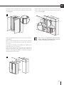
Once the appliances have been adjusted and
properly levelled, loosen the two screws holding
the sealing plate in position.
Lower the plate until flush with the floor, and re-
tighten the screws. This will ensure optimized
airflow through the condenser necessary for proper
operation.
> Next join them at the front attaching the plastic
connecting brackets with the supplied screws [ 3 ] .
Attach the bracket on top of the units (if applicable)
as per figure [ 4 ].
3
4
La page est en cours de chargement...
La page est en cours de chargement...
La page est en cours de chargement...
La page est en cours de chargement...
La page est en cours de chargement...
La page est en cours de chargement...
La page est en cours de chargement...
La page est en cours de chargement...
La page est en cours de chargement...
La page est en cours de chargement...
La page est en cours de chargement...
La page est en cours de chargement...
La page est en cours de chargement...
La page est en cours de chargement...
La page est en cours de chargement...
La page est en cours de chargement...
La page est en cours de chargement...
La page est en cours de chargement...
La page est en cours de chargement...
La page est en cours de chargement...
La page est en cours de chargement...
La page est en cours de chargement...
La page est en cours de chargement...
La page est en cours de chargement...
La page est en cours de chargement...
La page est en cours de chargement...
La page est en cours de chargement...
La page est en cours de chargement...
La page est en cours de chargement...
La page est en cours de chargement...
La page est en cours de chargement...
La page est en cours de chargement...
La page est en cours de chargement...
La page est en cours de chargement...
La page est en cours de chargement...
La page est en cours de chargement...
La page est en cours de chargement...
La page est en cours de chargement...
La page est en cours de chargement...
La page est en cours de chargement...
La page est en cours de chargement...
La page est en cours de chargement...
La page est en cours de chargement...
La page est en cours de chargement...
La page est en cours de chargement...
La page est en cours de chargement...
La page est en cours de chargement...
La page est en cours de chargement...
La page est en cours de chargement...
La page est en cours de chargement...
La page est en cours de chargement...
La page est en cours de chargement...
La page est en cours de chargement...
La page est en cours de chargement...
La page est en cours de chargement...
La page est en cours de chargement...
-
 1
1
-
 2
2
-
 3
3
-
 4
4
-
 5
5
-
 6
6
-
 7
7
-
 8
8
-
 9
9
-
 10
10
-
 11
11
-
 12
12
-
 13
13
-
 14
14
-
 15
15
-
 16
16
-
 17
17
-
 18
18
-
 19
19
-
 20
20
-
 21
21
-
 22
22
-
 23
23
-
 24
24
-
 25
25
-
 26
26
-
 27
27
-
 28
28
-
 29
29
-
 30
30
-
 31
31
-
 32
32
-
 33
33
-
 34
34
-
 35
35
-
 36
36
-
 37
37
-
 38
38
-
 39
39
-
 40
40
-
 41
41
-
 42
42
-
 43
43
-
 44
44
-
 45
45
-
 46
46
-
 47
47
-
 48
48
-
 49
49
-
 50
50
-
 51
51
-
 52
52
-
 53
53
-
 54
54
-
 55
55
-
 56
56
-
 57
57
-
 58
58
-
 59
59
-
 60
60
-
 61
61
-
 62
62
-
 63
63
-
 64
64
-
 65
65
-
 66
66
-
 67
67
-
 68
68
-
 69
69
-
 70
70
-
 71
71
-
 72
72
-
 73
73
-
 74
74
-
 75
75
-
 76
76


Bertazzoni REF24FCIPIXR Guide d'installation
- Taper
- Guide d'installation
dans d''autres langues
Documents connexes
Autres documents
-
Gaggenau WS 461 Manuel utilisateur
-
Hestan KWCR24OV Guide d'installation
-
Signature Kitchen Suite SKSCW241RP Guide d'installation
-
Rubi RNK24- Guide d'installation
-
Fhiaba BI30BI-LO Guide d'installation
-
Fhiaba FM24BWRLGS Guide d'installation
-
Fhiaba BKI36BI-LS Guide d'installation
-
Fhiaba BKI24B-RO Guide d'installation
-
Jenn-Air JBRFL30IGX Guide d'installation
-
Jenn-Air JBRFR36IGX Guide d'installation