
- 1 -
Sicherheitsbestimmungen
• Das Gerät darf nur von Personen
installiert und in Betrieb genommen
werden, die mit dieser Betriebsanleitung
und den geltenden Vorschriften über
Arbeitssicherheit und Unfallverhütung
vertraut sind.
• Beachten Sie die VDE- sowie die
örtlichen Vorschriften, insbesondere
hinsichtlich Schutzmaßnahmen.
• Beim Transport, bei der Lagerung und im
Betrieb die Bedingungen nach EN 60068-
2-78 einhalten (s. technische Daten).
• Durch Öffnen des Gehäuses oder eigen-
mächtige Umbauten erlischt jegliche
Gewährleistung.
• Montieren Sie das Gerät in einen
Schaltschrank; Staub und Feuchtigkeit
können sonst zu Beeinträchtigungen der
Funktionen führen.
• Sorgen Sie an allen Ausgangskontakten
bei kapazitiven und induktiven Lasten für
eine ausreichende Schutzbeschaltung.
• Die Sicherheitsfunktion muss mindestens
einmal im Monat ausgelöst werden.
Bestimmungsgemäße Verwendung
Das Sicherheitsschaltgerät PNOZ X7 ist
bestimmt für den Einsatz in
• NOT-AUS-Einrichtungen
• Sicherheitsstromkreisen nach VDE 0113,
Teil 1 und EN 60204-1 (z. B. bei bewegli-
chen Verdeckungen)
Das Gerät ist nicht für die Absicherung von
berührungslosen Verdeckungen geeignet,
da kein dynamischer Start möglich ist.
Geräteklassifikation:
• BG Fachausschuss Elektrotechnik
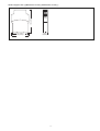
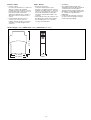
Gerätebeschreibung
Das Sicherheitsschaltgerät ist in einem
S-95-Gehäuse untergebracht. Das PNOZ
X7 24 V AC/DC kann mit 24 V AC oder 24 V
DC betrieben werden. Das PNOZ X7 AC
kann mit 42, 48, 110, 115, 120, 230 oder
240 V AC betrieben werden.
Zwischen dem NOT-AUS-Taster und dem
Starttaster besteht bei PNOZ X7 AC eine
galvanische Trennung.
Merkmale:
• Relaisausgänge: zwei Sicherheits-
kontakte (Schließer), zwangsgeführt
• Anschlussmöglichkeit für NOT-AUS-
Taster
• Statusanzeige
• Rückführkreis zur Überwachung externer
Schütze
Das Schaltgerät erfüllt folgende Sicherheits-
anforderungen:
• Schaltung ist redundant mit Selbst-
überwachung aufgebaut.
• Sicherheitseinrichtung bleibt auch bei
Ausfall eines Bauteils wirksam.
Safety Regulations
• The unit may only be installed and
operated by personnel who are familiar
with both these instructions and the
current regulations for safety at work and
accident prevention. Follow CEN and
local regulations especially as regards
preventative measures.
• Transport, storage and operating
conditions should all conform to EN
60068-2-78 (s. technical data).
• Any guarantee is void following opening of
the housing or unauthorised
modifications.
• The unit should be panel mounted,
otherwise dampness or dust could lead to
function impairment.
• Adequate protection must be provided on
all output contacts with capacitive and
inductive loads.
• The safety function must be triggered at
least once a month.
Conseils préliminaires
• La mise en oeuvre de l'appareil doit être
effectuée par une personne spécialisée
en installations électriques, en tenant
compte des prescriptions des différentes
normes applicables (NF, EN, VDE..),
notamment au niveau des risques
encourus en cas de défaillance de
l'équipement électrique.
• Respecter les exigences de la norme
EN 60068-2-78 lors du transport, du
stockage et de l'utilisation de l'appareil.
• L'ouverture du boîtier annule automati-
quement la clause de garantie.
• Installez le relais dans une armoire
électrique à l'abri de la poussière et de
l'humidité.
• Assurez-vous du pouvoir de coupure
des contacts de sortie en cas de charges
inductives ou capacitives
• La fonction de sécurité doit être activée
au moins une fois par mois.
Domaine d'utilisation
Le bloc logique PNOZ X7 est spécialement
conçu pour:
• les circuits d'arrêt d'urgence
• les circuits de sécurité d'après la norme
EN 60204/1 (par ex. protecteur)
L'appareil n'est pas adapté à la sur-
veillance de barrières immatérielles car une
validation dynamique n'est pas possible.
Homologations :
• BG Fachausschuss Elektrotechnik
Intended Applications
The Safety Relay PNOZ X7 can be used in:
• Emergency stop installations.
• Safety circuits according to VDE 0113 part
1 and EN 60204-1 (e.g. with movable
guards).
The unit is not suitable for use with non-
contact guards, as a dynamic start is not
possible.
Approvals:
• BG Fachausschuss Elektrotechnik
Description
The relay is enclosed in a 22.5 mm, S-95
housing. The PNOZ X7 24 VAC/DC is a
dual-voltage unit and the PNOZ X7 AC is
available with the following voltages: 42, 48,
110, 115, 120, 230 or 240 VAC.
There is galvanic isolation between the
E-STOP button and the reset button on the
PNOZ X7 AC version.
Features:
• Relay outputs: 2 (N/O) safety contacts,
positive-guided
• Connections for emergency stop button
• Status Indicators
• Feedback control loop for monitoring
external relays / contactors
The relay complies with the following safety
requirements:
• The circuit is redundant with built-in self-
monitoring.
• The safety function remains effective in
the case of a component failure.
Description de l'appareil
Le bloc logique PNOZ X7 est inséré dans
un boîtier S-95. Le PNOZ X7 24V AC/DC
peut être alimenté en 24 VAC ou 24 VDC.
Le PNOZ X7 AC peut être alimenté en 42,
48, 110, 115, 120, 230 ou 240 VAC.
Le PNOZ X7 AC dispose d'une isolation
galvanique entre le BP AU et le circuit de
réarmement.
Particularités :
• contacts de sortie : 2 contacts à
fermeture de sécurité, contacts liés
• raccordement pour poussoir AU ou
capteur
• LEDs de visualisation
• boucle de retour pour l'auto-contrôle des
contacteurs externes
Le bloc logique PNOZ X7 répond aux
exigences suivantes :
• conception redondante avec auto-
surveillance
• fonction de sécurité garantie même en
cas de défaillance d'un composant
électronique.
19 692-03
PNOZ X7 24 V AC/DC, PNOZ X7 AC
4 D Betriebsanleitung
4 GB Operating instructions
4 F Manuel d`utilisation
4 E Instrucciones de uso
4 I Istruzioni per l`uso
4 NL Gebruiksaanwijzing

- 2 -
• Bei jedem Ein-Aus-Zyklus der Maschine
wird automatisch überprüft, ob die Relais
der Sicherheitseinrichtung richtig öffnen
und schließen.
Funktionsbeschreibung
Das Schaltgerät dient dem sicherheits-
gerichteten Unterbrechen eines Sicherheits-
stromkreises.
Voraussetzung: Anlegen der Versorgungs-
spannung über den NOT-AUS-Taster,
Brücke zwischen Y1-Y2 oder Starttaster
zwischen Y1 und Y2 betätigt.
• Eingangskreis geschlossen (z. B. NOT-
AUS-Taster nicht betätigt)
Relais K1 und K2 gehen in Wirkstellung
und halten sich selbst. Die Sicherheits-
kontakte 13-14/23-24 sind geschlossen.
• Eingangskreis wird geöffnet (z. B. NOT-
AUS-Taster betätigt)
K1 und K2 fallen in die Ruhestellung
zurück. Die Sicherheitskontakte 13-14/23-
24 werden redundant geöffnet.
Betriebsarten
• Einkanaliger Betrieb:
Eingangsbeschaltung nach VDE 0113
und EN 60204, keine Redundanz im
Eingangskreis. Erdschlüsse im Taster-
kreis werden erkannt.
• Automatischer Start: Gerät ist aktiv,
sobald der Eingangskreis geschlossen ist.
• Manueller Start: Gerät ist erst dann aktiv,
wenn ein Starttaster betätigt wird.
Dadurch ist ein automatischer Start des
Schaltgeräts nach Spannungsausfall und
Spannungswiederkehr ausgeschlossen.
• Kontaktvervielfachung und Kontakt-
verstärkung durch Anschluss von
externen Schützen.
14
24
K2
K1
13 23
~
=
G
A2A1
A
1
2
Y1 Y2
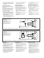
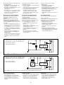
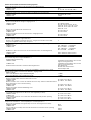
A:Einschaltlogik, zyklischer Test,
Steuerlogik/
Operating Logic, Cycle Test,
Control Logic/
Logique d'entrée, test cyclique,
logique de commande
1: Kanal 1/Channel 1/Canal 1
2: Kanal 2/Channel 2/Canal 2
Fig. 2: PNOZ X7 AC Schematisches Schaltbild/Connection Diagram/Schéma de principe
A:Einschaltlogik, zyklischer Test,
Steuerlogik/
Operating Logic, Cycle Test,
Control Logic/
Logique d'entrée, test cyclique,
logique de commande
1: Kanal 1/Channel 1/Canal 1
2: Kanal 2/Channel 2/Canal 2
Fig. 1: PNOZ X7 24 V AC/DC Schematisches Schaltbild/Connection Diagram/Schéma de principe
14
24
K2
K1
13 23
A2
A1
A
1
2
Y1 Y2
+
• The correct opening and closing of the
safety function relays is tested
automatically in each on-off cycle.
Function Description
Operating Modes
• Single-channel operation:
Input wiring according to VDE 0113 and
EN 60204, no redundancy in the input
circuit. Earth faults are detected in the
emergency stop circuit.
• Automatic reset: unit is active, as soon as
the input circuit is closed.
• Manual reset: unit is only active, when a
reset button has been pressed. Automatic
reset following a loss/return of supply
voltage is thereby prevented.
• Increase in the number of contacts
available by connecting external
contactors / relays.
• test cyclique du relais à chaque mise sous
tension de la machine.
Description du fonctionnement
Le bloc logique assure de façon sûre
Mode de fonctionnements
• Commande par 1 canal :
conforme aux prescriptions de la norme
EN 60204, pas de redondance dans le
circuit d'entrée.La mise à la terre du
circuit d'entrée est détectée.
• Réarmement automatique : le relais est
activé dès la fermeture du circuit
d'entrée.
• Réarmement manuel : le relais n'est
activé qu'après une impulsion sur le
poussoir de réarmement. Un réarmement
automatique du relais après une coupure
d'alimentation est ainsi impossible.
• Augmentation du nombre de contacts ou
du pouvoir de coupure par l'utilisation de
contacteurs externes
The relay provides a safety-oriented
interruption of a safety circuit.
Function: apply the operating voltage via the
E-Stop button, link between Y1-Y2 or
activate the reset button between Y1-Y2.
• Input circuit closed (e.g. emergency stop
button not operated):
Relays K1 and K2 energise and latch.
The safety contacts 13-14/23-24 are
closed.
• Input circuit opened (e.g. emergency stop
button operated):
K1 and K2 de-energise. The safety
contacts 13-14/23-24 are opened
redundantly.
l'ouverture d'un circuit de sécurité.
Préalables: tension d'alimentation présente
sur poussoir AU , ponts entre Y1-Y2 ou
poussoir sur Y1-Y2 actionné
• circuit d'entrée fermé (par ex. poussoir
AU non actionné)
Les relais K1 et K2 passe en position
travail et s'auto-maintiennent. Les
contacts de sécurité 13-14/23-24 se
ferment.
• circuit d'entrée ouvert (par ex. poussoir
AU actionné)
K1 et K2 retombent. Les contacts de
sécurité 13-14/23-24 s'ouvrent de façon
redondante.

- 3 -
Montage
Das Sicherheitsschaltgerät muss in einen
Schaltschrank mit einer Schutzart von mind.
IP 54 eingebaut werden. Zur Befestigung
auf einer Normschiene hat das Gerät ein
Rastelement auf der Rückseite. Sichern Sie
das Gerät bei Montage auf einer senkrech-
ten Tragschiene (35 mm) durch ein
Halteelement wie z. B. Endhalter oder
Endwinkel.
Inbetriebnahme
Beachten Sie bei der Inbetriebnahme:
• Vor die Ausgangskontakte eine
Sicherung (6 A flink oder 4 A träge)
schalten, um das Verschweißen der
Kontakte zu verhindern.
• Berechnung der max. Leitungslänge I
max
im Eingangskreis:
R
lmax
R
l
/ km
I
max
=
R
lmax
= max. Gesamtleitungswiderstand
(s. technische Daten)
R
l
/km = Leitungswiderstand/km
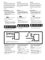
PNOZ X7 AC:
- Ringleitung, 1 Phase (s. Fig. 3): 1 km
- Stichleitung (s. Fig. 4): max. Länge der
Stichleitung l
s
und max. Kabelkapazität
C
L
in Abhängigkeit der Versorgungs-
spannung U
B
:
U
B
[V] 42 48 110 115 120 230 240
C
L
[nF] 37,5 37,5 37,5 37,5 37,5 7,5 7,5
Werte für die max. Kabelkapazität C
L
unbedingt einhalten, sonst kann das
Gerät fehlerhaft reagieren.
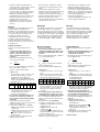
Fig. 3: Leitungslänge lr bei Ringleitung/Cable length Ir
with a ring circuit/Longueur de câblage lr en
boucle
A2
A1
U
B
lr
N
PNOZ X7 AC
A2
A1
U
B
ls
N
PNOZ X7 AC
Fig. 4: Leitungslänge ls der Stichleitung/Cable length
Is of the branch line/Longueur câblage Is en
dérivation
• Keine kleinen Ströme mit Kontakten
schalten, über die zuvor große Ströme
geführt wurden.
• Leitungsmaterial aus Kupferdraht mit
einer Temperaturbeständigkeit von
60/75 °C verwenden.
• Geräte unbedingt erden:
- PNOZ X7 24 V AC/DC an
Anschlussklemme A2
- PNOZ X7 AC an Anschlussklemme
Nur so kann das Gerät Erdschlüsse im
Stromkreis Y1-Y2 erkennen.
• Angaben im Kapitel "Technische Daten"
unbedingt einhalten.
Installation
The safety relay must be panel mounted
(min. IP 54). There is a notch on the rear of
the unit for DIN-Rail attachment. If the unit is
installed on a vertical mounting rail (35 mm),
ensure it is secured using a fixing bracket
such as end bracket.
• Low currents should not be switched
across contacts across which high
currents have previously been
switched.
• Use copper wire that can withstand
60/75 °C.
• The unit must be earthed
- PNOZ X7 24 VAC/DC at the connection
terminal A2
- PNOZ X7 AC at the terminal marked
This enables earth faults in the circuit Y1-
Y2 to be detected
• Important details in the section “Technical
Data” should be noted and adhered to.
Montage
Le relais doit être monté dans l'armoire
électrique ayant au min. un indice de
protection IP 54. Sa face arrière permet un
montage rapide sur rail DIN. Immobilisez
l'appareil monté sur un rail DIN vertical (35
mm) à l'aide d'un élément de maintien
comme par ex. un support ou une équerre
terminale.
• Ne pas commuter de faibles intensités
par des contacts ayant au préalable
commutés des intensités plus
élevées.
• Utiliser uniquement des fils de câblage en
cuivre 60/75 °C.
• Le PNOZ X7 doit être toujours relié à la
terre :
- PNOZ X7 24 V AC/DC par la borne A2
- PNOZ X7 AC par la borne
Ce câblage permet de détecter une mise
à la terre du circuit Y1-Y2.
• Respectez les données indiquées dans
les caractéristiques techniques.
Operation
Please note for operation:
• To prevent contact welding, a fuse
(6 A quick / 4 A slow acting) must be
connected before the output contacts.
• Calculate the max. cable runs l
max
in the
input circuit:
R
lmax
R
l
/ km
I
max
=
R
lmax
= Max. Total cable resistance
(see technical details)
R
l
/km = cable resistance/km
PNOZ X7 AC:
- ring circuit (Fig. 3): 1 km
- branch line (Fig. 4): max. length of the
branch line I
s
and max. capacity will
depend on the supply voltage U
B
:
U
B
[V] 42 48 110 115 120 230 240
C
L
[nF] 37,5 37,5 37,5 37,5 37,5 7,5 7,5
Values for the max. capable capacity C
L
must be adhered to, otherwise the unit
could malfunction.
Mise en oeuvre
Remarques préléminaires :
• Protection des contacts de sortie par
des fusibles 6 A rapides ou 4 A
normaux pour éviter leur soudage.
• Calcular les longueurs de câblage max
I
max
dans le circuit d’entrée:
R
lmax
R
l
/ km
I
max
=
R
lmax
= résistivité de câblage totale max.
(voir les caractéristiques techniques)
R
l
/km = résistivité de câblage/km
PNOZ X7 AC :
- Câblage en boucle (v. Fig. 3): 1 km
- Câblage en dérivation (v. Fig. 4): long.
max. de la dérivation l
s
et capacité max.
dépend de la tension d'alimentation U
B
:
U
B
[V] 42 48 110 115 120 230 240
C
L
[nF] 37,5 37,5 37,5 37,5 37,5 7,5 7,5
Respecter impérativement la capacité
max. C
L
du câble pour prévenir un
mauvais fonctionnement du relais.

- 4 -
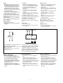
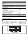
Ablauf:
• NOT-AUS-Taster zwischen Klemme A1
des PNOZ und die Klemme L+/L1 der
Versorgungsspannung anschließen. 0V-
Seite der Versorgungsspannung mit A2
verbinden. Die LED "Power" leuchtet.
• Rückführkreis mit automatischem Start:
Brücke oder externe Kontakterweiterungen
an Y1-Y2 anschließen.
• Rückführkreis mit manuellem Start:
Starttaster an Y1-Y2 und externe Kontakt-
erweiterungen in Reihe schalten.
Die Sicherheitskontakte sind geschlossen.
Die LED "CH.1/CH.2" leuchtet. Das Gerät ist
betriebsbereit. Der Starttaster kann wieder
geöffnet werden.
Wird der Eingangskreis geöffnet (NOT-AUS-
Taster betätigt), öffnen die Sicherheitskon-
takte 13-14/23-24.
Wieder aktivieren
• Eingangskreis schließen.
• Bei manuellem Start zusätzlich Starttaster
betätigen.
14
K3 K4
13
Y1 Y2
K3
K4
1L1
1L2
Fig. 6: Verstärkung (Vervielfältigung) der
Kontakte durch externe Schütze; einkanalig;
automatischer Start/Increase in the number
of available contacts by connection of
external contactors/relays; single channel;
automatic reset/Multiplication des contacts à
l'aide de contacteurs externes; commande
par 1 canal; réarmement automatique
U
B
(L+)
Y1
A1
Y2
Fig. 5: Eingangskreis einkanalig: NOT-AUS-
Beschaltung; manueller Start/
Single channel input circuit: Emergency Stop
wiring; manual reset/
Commande par 1 canal : circuit AU, avec
réarmement manuel
Fehler - Störungen
• Erdschluss im Start-/Rückführkreis:
Die Versorgungsspannung bricht zusam-
men und die Sicherheitskontakte werden
über eine elektronische Sicherung
geöffnet. Nach Wegfall der Störungs-
ursache und Abschalten der Versorgungs-
spannung für ca. 1 Minute ist das Gerät
wieder betriebsbereit.
• Fehlfunktionen der Kontakte: Bei ver-
schweißten Kontakten ist nach Öffnen des
Eingangskreises keine neue Aktivierung
möglich.
To operate:
• Connect the E-Stop button between
terminal A1 of the PNOZ and the supply
L+/L1 of the operating voltage. Connect
terminal A2 with the 0V side of the
operating voltage. The LED “Power” is
illuminated.
• Feedback control loop with automatic
reset: link Y1-Y2 or connect external
contactors
• Feedback control loop with manual reset:
Connect reset button at Y1 - Y2 or connect
external contactors in series
The safety contacts are closed. The LED
'CH.1/CH.2' is illuminated. The unit is ready
for operation. The reset button can be
opened again, i.e. released.
If the input circuit is opened (E-Stop
activated), the safety contacts 13-14/23-24
open.
Reactivation
• Close the input circuit.
• With manual reset, the reset button must
also be pressed.
Mise en oeuvre :
• Câblez le contact du poussoir AU entre
les bornes A1 (L+) du PNOZ X7 et le
potentiel L+/L1 de la tension
d'alimentation.
Relier la borne A2 (L-) du PNOZ X7 au
0V de la tension d'alimentation. La LED
"Power" s'allume.
• Boucle de retour avec réarmement auto.:
pont entre Y1-Y2 ou câblage des
contacts externes.
• Boucle de retour avec réarmement
manuel :
Branchement d'un poussoir entre les
bornes Y1-Y2, en série avec les
contacts externes.
Les contacts de sécurité sont fermés. La
LED CH.1/CH.2 est allumée.
Si le circuit d'entrée est ouvert (AU
actionné), les contacts 13-14/23-24
s'ouvrent.
Remise en route :
• fermer le circuit d'entrée
• en cas de réarmement manuel, appuyer
sur le poussoir Y1-Y2.
Faults/Disturbances
• Earth fault in the reset circuit/feedback
loop:
Supply voltage fails and the safety
contacts are opened via an electronic fuse.
Once the cause of the fault has been
removed and operating voltage is switched
off, the unit will be ready for operation after
approximately 1 minute.
• Faulty contact functions: In the case of
welded contacts, no further activation is
possible following an opening of the input
circuit.
Erreurs- Défaillances
• Défaut de masseau circuit de réarmement/
de boucle de retour :
La tension d’alimentation chute et les
contacts de sécurité sont ouverts par un
fusible électronique. Une fois la cause du
défaut éliminée et la tension d’alimentation
coupée, l’appareil est à nouveau prêt à
fonctionner après environ 1 minute.
• Défaut d'un contact : en cas de collage
d'un contact après ouverture du circuit
d'entrée, un nouvel réarmement est
impossible.
La page est en cours de chargement...

- 6 -
24 V
42, 48, 110, 115, 120, 230, 240 V
-15 % ... +10 %
AC: 3,0 VA, DC: 1,5 W
2,0 VA
AC: 50 ... 60 Hz
DC: 160 %
24 V AC/DC, 50 mA
42 V AC, 49 mA; 48 V AC, 45 mA;
110 V AC, 14 mA; 115 V AC, 17 mA;
120 V AC, 18 mA; 230 V AC, 8 mA;
240 V AC, 7 mA
24 V DC, 210 mA
24 V DC, 40 mA
24 V DC, 210 mA
24 V DC, 40 mA
2
AC1: 240 V/0,01 ... 6 A/1500 VA
DC1: 24 V/0,01 ... 4 A/100 W
AC1: 240 V/0,01 ... 4 A/1500 VA
DC1: 24 V/0,01 ... 6 A/100 W
AC15: 230 V/5 A; DC13: 24 V/6 A
AC15: 230 V/4 A; DC13: 24 V/4 A
AgSnO
2
+ 0,2 µm Au
6 A flink/quick acting/rapide oder /or/ou
4 A träge/slow acting/normeaux
4 A flink/quick acting/rapide oder /or/ou
4 A träge/slow acting/normeaux
24 V AC/DC: 4 A,
Charakteristik /Characteristic/
Caractéristiques B/C
15 Ohm
15 Ohm
typ. 50 ms, max. 150 ms
typ. 230 ms, max. 700 ms
typ. 50 ms, max. 150 ms
typ. 230 ms, max. 700 ms
typ. 35 ms, max. 150 ms
typ. 140 ms, max. 700 ms
typ. 45 ms, max. 70 ms
typ. 70 ms, max. 100 ms
typ. 45 ms, max. 70 ms
typ. 70 ms, max. 100 ms
50 ms
120 ms
150 ms
120 ms
20 ms
Versorgungsspannung U
B
/Operating Voltage/Tension d’alimentation
PNOZ X7 AC/DC
PNOZ X7AC
Spannungstoleranz/Voltage Tolerance/Plage de la tension d’alimentation
Leistungsaufnahme bei U
B
/Power Consumption/Consommation
PNOZ X7 AC/DC
PNOZ X7 AC
Frequenzbereich/Frequency range/Fréquence
Restwelligkeit/Residual Ripple/Ondulation résiduelle
Spannung und Strom an/Voltage, Current at //Tension et courant du
Eingangskreis/Input circuit/circuit d’entrée
PNOZ X7 AC/DC
PNOZ X7 AC
Startkreis/Reset circuit/circuit de réarmement
PNOZ X7 AC/DC
PNOZ X7 AC
Rückführkreis/Feedback loop/circuit de boucle de retour
PNOZ X7 AC/DC
PNOZ X7 AC
Ausgangskontakte nach EN 954-1/Output Contacts to EN 954-1/
Contacts de sortie d'après EN 954-1
Sicherheitskontakte (S), Kategorie 2/safety contacts N/O, category 2/
contacts de sécurité (F), catégorie 2
Gebrauchskategorie nach/Utilization category to/Catégorie d’utilisation d'après
EN 60947-4-1
PNOZ X7 AC/DC
PNOZ X7 AC
EN 60947-5-1(DC13: 6 Schaltspiele/Min, 6 cycles/min, 6 manoeuvres/min)
PNOZ X7 AC/DC
PNOZ X7 AC
Kontaktmaterial/Contact material/Matériau contact
Kontaktabsicherung extern nach/External Contact Fuse Protection/Protection des contacts
EN 60 947-5-1
Schmelzsicherung/Blow-out fuse/Fusibles
PNOZ X7 AC/DC
PNOZ X7 AC
Sicherungsautomat/Safety cut-out/Dijoncteur
Max. Gesamtleitungswiderstand R
lmax
Eingangskreise/Max. overall cable resistance R
lmax
input circuits/ Résistance de câblage totale max. R
lmax
circuits d'entrée
PNOZ X7 AC/DC
einkanalig DC/Single-channel DC/Commande par 1 canal DC
einkanalig AC/Single-channel AC/Commande par 1 canal AC
Einschaltverzögerung/Switch-on delay/Temps de réarmement
Automatischer Start/Automatic reset/Réarmement automatique
PNOZ X7 AC/DC
PNOZ X7 AC
Automatischer Start nach Netz-Ein/Automatic reset after Power-On/Réarmement automatique
après mise sous tension
PNOZ X7 AC/DC
PNOZ X7 AC
Manueller Start/Manual reset/Réarmement manuel
PNOZ X7 AC/DC
PNOZ X7 AC
Rückfallverzögerung /Delay-on De-Energisation /Temps de retombée
bei NOT-AUS/at E-STOP/en cas d'arrêt d'urgence
PNOZ X7 AC/DC
PNOZ X7 AC
bei Netzausfall/with power failure/en cas de coupure d'alimentation
PNOZ X7 AC/DC
PNOZ X7 AC
Wiederbereitschaftszeit bei max. Schaltfrequenz 1/s/recovery time at max. switching frequency
1/s/temps de remise en service en cas de fréquence de commutation max. 1/s
nach NOT-AUS/after E-STOP/après l'arrêt d'urgence
PNOZ X7 AC/DC
PNOZ X7 AC
nach Netzausfall/after power failure/après une coupure d'alimentation
PNOZ X7 AC/DC
PNOZ X7 AC
Überbrückung bei Spannungseinbrüchen/Max. supply interruption before
de-energisation/tenue aux micro-coupures
Technische Daten/Technical Data/Caractéristiques techniques

- 7 -
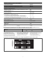
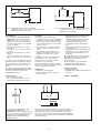
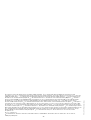
Lebensdauer der Ausgangsrelais/Service Life of Output relays/Durée de vie des relais de sortie
10
1
10 100 1000 10000
Nennbetriebstrom (A)
Nominal operating current (A)
Courant coupé (A)
0.1
DC13: 24 V
AC15: 230 V
AC1: 230 V
DC1: 24 V
Schaltspielzahl x 10
3
Cycles x 10
3
Nombre de manvres x 10
3
Es gelten die 09/04 aktuellen Ausgaben der
Normen
The version of the standards current at 09/04
shall apply
Se référer à la version des normes en vigeur
au 09/04.
EMV/EMC/CEM
Schwingungen nach/Vibration to/Vibrations d'après EN 60068-2-6
Frequenz/Frequency/Fréquences
Amplitude/Amplitude/Amplitude
Klimabeanspruchung/Climate Suitability/Conditions climatiques
Luft- und Kriechstrecken/Airgap Creepage/Cheminement et claquage
Umgebungstemperatur/Operating Temperature/Température d’utilisation
Lagertemperatur/Storage Temperature/Température de stockage
Schutzart/Protection/Indice de protection
Einbauraum (z. B. Schaltschrank)/Mounting (eg. panel)/Lieu d'implantation (ex. armoire)
Gehäuse/Housing/Boîtier
Klemmenbereich/Terminals/Bornes
Gehäusematerial/housing material/matériau du boîtier
Gehäuse/Housing/Boîtier
Front/front panel/face avant
Max.Querschnitt des Außenleiters (Schraubklemmen)/Max. cable cross section (screw
terminals)/Capacité de raccordement (borniers à vis)
1 Leiter, flexibel/1 core, flexible/1 conducteur souple
2 Leiter gleichen Querschnitts, flexibel mit Aderendhülse, ohne Kunststoffhülse/
2 core, same cross section flexible with crimp connectors, without insulating sleeve/
2 conducteurs de même diamètre souple avec embout, sans chapeau plastique
ohne Aderendhülse oder mit TWIN-Aderendhülse/without crimp connectors or with TWIN
crimp connectors/souple sans embout ou avec embout TWIN
Anzugsdrehmoment für Schraubklemmen/Torque setting for screw terminals/
couple de serrage (borniers à vis)
Abmessungen (Schraubklemmen) H x B x T/Dimensions H x W x D (screw terminals)/
Dimensions (borniers à vis) H x P x L
Einbaulage/Fitting Position/Position de travail
Gewicht/Weight/Poids
PNOZ X7 AC/DC
PNOZ X7 AC
Anzahl der Kontakte/number of contacts/nombre des contacts 2 1
PNOZ X7 AC
I
max
3,0 A 4,0 A
Max. Dauerstrom bei gleichzeitiger Belastung mehrerer Kontakte/Total current switching capability across all
contacts/Intensité commutée max. en cas de charge sur plusieurs contacts (AC1, DC1)
EN 60947-5-1, EN 61000-6-2
10 ... 55 Hz
0,35 mm
EN 60068-2-78
VDE 0110-1
-10 ... +55 °C
-40 ... +85 °C
IP54
IP40
IP20
PPO UL 94 V0
ABS UL 94 V0
0,20 ... 4 mm
2
0,20 ... 2,5 mm
2
0,20 ... 2,5 mm
2
0,6 Nm
87 x 22,5 x 121 mm
beliebig/any/indifférente
190 g
225 g
To prevent failure of the unit, all output
contacts should be fused adequately. With
capacative loads, possible current peaks are
to be avoided. With DC contactors/relays
use suitable spark suppression to ensure
extended life of the contactors/relays.
Um ein Versagen der Geräte zu verhindern, an
allen Ausgangskontakten für eine aus-
reichende Funkenlöschung sorgen. Bei
kapazitiven Lasten sind eventuell auftretende
Stromspitzen zu beachten. Bei DC-Schützen
Freilaufdioden zur Funkenlöschung einsetzen,
um die Lebendauer der Schütze zu erhöhen.
Prévoir un dispositif d’extinction d’arc sur les
contacts de sortie pour éviter un éventuel
disfonctionnement du relais.
Tenir compte des pointes d’intensité en cas
de charge capacitive. Equiper les
contacteurs DC de diodes de roue libre .
La page est en cours de chargement...
La page est en cours de chargement...
La page est en cours de chargement...
La page est en cours de chargement...
La page est en cours de chargement...
La page est en cours de chargement...
La page est en cours de chargement...
La page est en cours de chargement...
La page est en cours de chargement...
-
 1
1
-
 2
2
-
 3
3
-
 4
4
-
 5
5
-
 6
6
-
 7
7
-
 8
8
-
 9
9
-
 10
10
-
 11
11
-
 12
12
-
 13
13
-
 14
14
-
 15
15
-
 16
16


PILZ PNOZ X7 24V AC Le manuel du propriétaire
- Taper
- Le manuel du propriétaire
- Ce manuel convient également à
dans d''autres langues
- italiano: PILZ PNOZ X7 24V AC Manuale del proprietario
- English: PILZ PNOZ X7 24V AC Owner's manual
- español: PILZ PNOZ X7 24V AC El manual del propietario
- Deutsch: PILZ PNOZ X7 24V AC Bedienungsanleitung
- Nederlands: PILZ PNOZ X7 24V AC de handleiding
Documents connexes
Autres documents
-
Kimex 031-1021 Guide d'installation
-
-
 Allen-Bradley Minotaur MSR310P Guide d'installation
-
SICK UE43-6MF Mode d'emploi
-
-
-
-
EDWARDS INT-22.5R1-24 Guide d'installation
-
-
