
1
WARNING: Improper installation, adjustment,
alteration, service or maintenance can cause
property damage, injury or death. Read
the installation, operating and maintenance
instructions thoroughly before installing or
servicing this equipment.
FOR YOUR SAFETY: Do not store or use
gasoline or other ammable vapors or liquids
in the vicinity of this or any other appliance.
WARNING: This appliance shall be installed
in accordance with current regulations and
used only in well-ventilated space. Refer to
instructions before installing and using this
appliance.
In addition, there should be posted, in a
prominent location, detailed instructions to
be followed in the event the operator smells
gas. Obtain the instructions from the local
gas supplier.
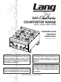
GAS
COUNTERTOP RANGE
GHP2, GHP4, GHP6, GHP8
Installation and
Operation
Instructions
2M-W1662 Rev. - 3/29/11
Retain This Manual for Future Reference.

2
SAFETY SYMBOL
Model No.:
Serial No.:
Voltage:
1-Phase or 3 Phase:
Purchased From:
Location:
Purchase Date:
Installed Date:
These symbols are intended to alert the user to the presence of important operating
and maintenance instructions in the manual accompanying the appliance.
FOR YOUR SAFTEY
DO NOT STORE OR USE GASOLINE OR OTHER FLAMMABLE VAPORS AND LIQUIDS IN
THE VICINTIY OF THIS OR ANY OTHER APPLIANCE.
The installation of the Appliance must conform to the NATIONAL FUEL GAS CODE "ANSI Z223.1 - LATEST
EDITION" AND ALL LOCAL GAS COMPANY RULES AND REGULATIONS.
IN CANADA INSTALLATION SHALL BE IN ACCORDANCE WITH THE CURRENT CAN/CGA-B149.1 NATURAL
GAS INSTALLATION CODE OR CAN/CGA-B149.2 PROPANE INSTALLATION CODE AND LOCAL CODES WHERE
APPLICABLE.
POST IN PROMINENT LOCATION
INSTRUCTIONS TO BE FOLLOWED IN THE EVENT USER SMELLS GAS. THIS INFORMATION
SHALL BE OBTAINED BY CONSULTING YOUR LOCAL GAS SUPPLIER. AS A MINIMUM, TURN
OFF THE GAS AND CALL YOUR GAS COMPANY AND YOUR AUTHORIZED SERVICE AGENT.
EVACUATE ALL PERSONNEL FROM THE AREA.
WARNING
IMPROPER INSTALLATION, ADJUSTMENT, ALTERATION, SERVICE OR MAINTENANCE CAN
CAUSE PROPERTY DAMAGE, INJURY OR DEATH. READ THE INSTALLATION, OPERATION
& MAINTENANCE INSTRUCTIONS THOROUGHLY BEFORE INSTALLING OR SERVICING THIS
EQUIPMENT.
WARNING
RISK OF FIRE OR ELECTRIC SHOCK
DO NOT OPEN
WARNING, TO REDUCE THE RISK OF ELECTRICAL SHOCK, DO NOT REMOVE
CONTROL PANEL. NO USER-SERVICABLE PARTS INSIDE.
REPAIRS SHOULD BE DONE BY AUTHORIZED SERVICE PERSONNEL ONLY.
NOTICE
Using any part other than genuine Lang factory supplied parts relieves the manufacturer of all liability.
Lang reserves the right to change speci cations and product design without notice. Such
revisions do not entitle the buyer to corresponding changes, improvements, additions or
replacements for previously purchased equipment.
Due to periodic changes in designs, methods, procedures, policies and regulations, the
specifications contained in this sheet are subject to change without notice. While Lang
Manufacturing exercises good faith efforts to provide information that is accurate, we are
not responsible for errors or omissions in information provided or conclusions reached as a
result of using the speci cations. By using the information provided, the user assumes all risks in con-
nection with such use.
MAINTENANCE AND REPAIRS
Contact your local dealer for service or required maintenance. Please record the model number, serial
number, voltage and purchase & Installation Information in the area below and have it ready when you
call to ensure a faster service.

3
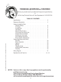
TABLE OF CONTENTS
Specications . . . . . . . . . . . . . . . . . . . . . . . . . . . . . . 4
Equipment Description ..
. . . . . . . . . . . . . . . . . . . . . . . .5
General Installation Data
Exhaust Canopy.
. . . . . . . . . . . . . . . . . . . . . . . . . . 6
Air Supply. . . . . . . . . . . . . . . . . . . . . . . . . . . . . . 6
Leveling Unit .. .. .. .. .. .. .. .. .. .. .. .. .. .. .. .. .. .. .. .. .. .. .. .. .. .. .. ..7
Gas Piping. . . . . . . . . . . . . . . . . . . . . . . . . . . . . . 8
Manual Shut-Off Valve .. . . . . . . . . . . . . . . . . . . . . . .8
Connecting Gas Supply Line.. . . . . . . . . . . . . . . . . . . .8
Propane Gas Conversion. . . . . . . . . . . . . . . . . . . . . . 8
Checking for Gas Leaks. . . . . . . . . . . . . . . . . . . . . . . 8
Pilot Lighting Instructions . . . . . . . . . . . . . . . . . . . . . . 9
Burner Ignition & Adjustment.. . . . . . . . . . . . . . . . . . . .9
General Operating Instructions
Drip Pan.
. . . . . . . . . . . . . . . . . . . . . . . . . . . . . .10
Burner Operation.. . . . . . . . . . . . . . . . . . . . . . . . . 10
Lighting.. . . . . . . . . . . . . . . . . . . . . . . . . . . . . . 10
Broiling .. . . . . . . . . . . . . . . . . . . . . . . . . . . . . . 10
Tilting the Grate. . . . . . . . . . . . . . . . . . . . . . . . . . .10
Shutting Down Instructions.. . . . . . . . . . . . . . . . . . . . 10
Cleaning. . . . . . . . . . . . . . . . . . . . . . . . . . . . . . .10
Wiring Diagram..
. . . . . . . . . . . . . . . . . . . . . . . . . . . 11
Exploded View & Parts List . .
. . . . . . . . . . . . . . . . . . . 12 - 16
PROBLEMS, QUESTIONS or CONCERNS
Before you proceed consult you authorized Lang service agent directory
or
Call the Lang Technical Service & Parts Department at 1-800-438-5264.
NOTICE Service on this or any other Lang appliance must be performed by
qualied personnel only
.
Consult your Lang Authorized Service Agent Directory.
You can call our toll free number 1-800-438-5264 or
visit our website www.langworld.com for the service agent nearest you.
2M-W1662 Operation Manual - Lang Gas Countertop Range, GHP Series

4
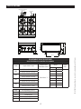
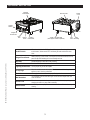
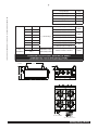
SPECIFICATIONS
6 1/8”
4”
3”
14 7/8”
15 5/8”
18 1/2”
GAS INLET
120V Electrical Connection
5 1/2’ Ft Cord
IL2180
EQUIPMENT SPECIFICATIONS
GAS CHEFSERIES COUNTERTOP RANGES
Model Height x Width x Depth
Clearance from
combustible surface*
Weight
Freight
Class
Actual Shipping
GHP2
15 3/8” x 11 7/8” x 28 3/16”
Sides & Back: 7”
(39.1cm x 30.2cm x 71.6cm)
GHP4
15 3/8” x 23 7/8” x 28 3/16”
(39.1cm x 60.6cm x 71.6cm)
GHP6
15 3/8” x 35 7/8” x 28 3/16”
(39.1cm x 91.1cm x 71.6cm)
GHP8
15 3/8” x 47 7/8” x 28 3/16”
(39.1cm x 121.6 x 71.6cm)
* Noncombustible oor only
Model Gas Requirment (3/4” NPT)
GHP2 64,000 BTU/hr
GHP4 128,000 BTU/hr
GHP6 192,000 BTU/hr
GHP8 256,000 BTU/hr
2M-W1662 Operation Manual - Lang Gas Countertop Range, GHP Series
2M-W1662 Operation Manual - Lang Gas Countertop Range, GHP Series

5
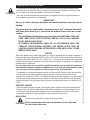
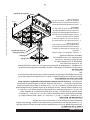
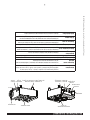
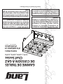
EQUIPMENT DESCRIPTION
On/Off
Switch
Hinged
Front Panel
Drip
Pan
Burner
Knob
Gas
Inlet
Wall
Mounting
Power
Cord
Burner Grate
Optional
“Instant-ON”
4” Adj. Legs Standard
(Tall Legs & Casters Optional)
Lighting
Instructions
IL2181
On/Off Switch
When the switch is in the "ON" position, it allows gas to ow through the solenoid
to the burners. When turned "OFF" the ow of gas ends and the unit shuts
down.
Hinged Front Panel
Held in place by (2) two screws, once they & the knobs are removed, the front
panel can ip down allowing the unit to be easily serviced.
Drip Pan Catches drippings & removes for easy cleaning
Burner Knob Provide individual control to the front and rear burners
Lighting Instructions List the proper way to use the hotplate
4" Adj Legs
Allow for ventilation under the hotplate. Provides a meand of leveling the
appliance, and of cleaning underneath.
Gas Inlet Gas supply should be connected by a qualied gas installer
Wall Restraint
The installation shall be made with a gas connecctor that complies with local
codes connectors.
Power Cord
This unit comes provided with a power cord specic to it needs, replacing or
changing the cord in any way voids its warranty.
Burner Grate
Holds food product at proper distance from burner ame. Remove for easy
cleaning.
2M-W1662 Operation Manual - Lang Gas Countertop Range, GHP Series
2M-W1662 Operation Manual - Lang Gas Countertop Range, GHP Series

6
GENERAL INSTALLATION DATA
This equipment is designed and sold for commercial use only by personnel trained and
experienced in its operation and is not sold for consumer use in and around the home nor
for use directly by the general public in food service locations.
The Lang Chefseries® gas countertop range is equipped for the type of gas indicated on
the nameplate mounted on the side panel.
-IMPORTANT-
Be sure to remove all paper protection and packing material from unit prior to
lighting.
Clearance from non-combustible construction must be 7" minimum from back
and sides, there must be a 4" space from the bottom of the unit to the counter
surface.
The installation of the Appliance must conform to the NATIONAL FUEL GAS
CODE "ANSI Z223.1 - LATEST EDITION" AND ALL LOCAL GAS COMPANY
RULES AND REGULATIONS.
IN CANADA INSTALLATION SHALL BE IN ACCORDANCE WITH THE
CURRENT CAN/CGA-B149.1 NATURAL GAS INSTALLATION CODE OR
CAN/CGA-B149.2 PROPANE INSTALLATION CODE AND LOCAL CODES
WHERE APPLICABLE.
NOTICE
When this appliance is installed with casters, it must be installed with the casters supplied, a
connector complying with either ANSI Z21.69 or CAN/CGA-6.16 and a quick-disconnect device
complying with either ANSI Z21.41 or CAN1-6.9. It must also be installed with restraining
means to guard against transmission of strain to the connector, as specied in the appliance
manufacturer's instructions.
For your protection, we recommend a qualied installing agency install this appliance.
They should be familiar with gas installations and your local gas requirements. In any
case, your gas company should be called to approve the nal installation.
This appliance, its pressure regulator and its individual shutoff valve must be disconnected
from the gas supply piping system during any pressure testing of that system at test
pressures in excess of 1/2 PSIG. This appliance and its pressure regulator must be isolated
from the gas supply piping system by closing its individual manual shutoff valve during any
pressure testing of the gas supply piping system at test pressures equal to or less than 1/2
PSIG.
EXHAUST CANOPY
Open hot plates inherently create a good deal of heat, moisture and fumes and should be
installed under an efcient exhaust hood with ame proof lters. A vertical distance of not
less than 48" shall be provided between the top of the appliance and lters or any other
combustible material. Exhaust installation must conform to local codes.
AIR SUPPLY
Provisions for adequate air supply must be provided.
Air for combustion enters from the bottom & front of the unit.
Do not obstruct this area.
CAUTION
CAUTION
2M-W1662 Operation Manual - Lang Gas Countertop Range, GHP Series
2M-W1662 Operation Manual - Lang Gas Countertop Range, GHP Series

IL2182
7
GENERAL INSTALLATION DATA (continued)
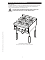
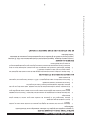
LEVELING UNIT
This range is supplied with 4 feet or oor stand legs which must be screwed into the body.
Unit must be level. Level unit by adjusting the (4) feet which have an adjustment of.
1-3/4" for accurate and perfect line-up with other units.
DO NOT INSTALL WITHOUT ATTACHING FEET OR SUPPLIED
STAND LEGS AND SHELF - DO NOT REMOVE FEET.
CAUTION
Model GHP4 with Standard 4" legs. .
Tall legs and casters are also available as an option.
2M-W1662 Operation Manual - Lang Gas Countertop Range, GHP Series
2M-W1662 Operation Manual - Lang Gas Countertop Range, GHP Series

8
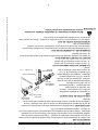
FLOW
BACK OF UNIT
IL1828a
DRIP LEG*
GAS
SHUT-OFF
VALVE*
SUPPLIED
REGULATOR
* by others
GAS
SUPPLY*
VENT
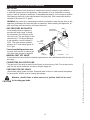
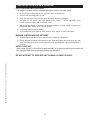
GENERAL INSTALLATION DATA (continued)
GAS PIPING
Gas piping shall be of such size and so installed as to provide a supply of gas sufcient
to meet the full gas input of the appliance. If the appliance is to be connected to existing
piping, it shall be checked to determine if it has adequate capacity. Joint compound shall be
used sparingly and only on the male threads of the pipe joints. Such compounds shall be
resistant to the action of L.P. gases.
WARNING: Any loose dirt or metal particles which are allowed to enter the gas lines on this
appliance will damage the valve and affect its operation. When installing this appliance, all
pipe and ttings must be free from all internal loose dirt.
GAS PRESSURE REGULATOR
A convertible pressure regulator is
provided with each range. It should
be connected to the inlet pipe at the
rear of the unit. The gas supply is then
connected to it. The supply pressure
to the regulator is not to exceed 1/2
PSIG. The water column manifold
pressure for 5" with natural gas & 10"
for LP gas.
Correct manifold pressures are:
5 inches water column for natural gas
10 inches water column for propane
MANUAL SHUT OFF VALVE
A manual shut off valve should be installed upstream from the manifold and within six feet of
the range.
CONNECTING GAS SUPPLY LINE
The gas inlet of the range is sealed at the factory to prevent entry of dirt. Do not remove this
seal until the actual connection is made to the gas supply line.
CHECKING FOR GAS LEAKS
Check entire piping system for leaks. Soap and water solution or other material acceptable
for the purpose, shall be used in locating gas leakage.
Matches, candle ame or other sources of ignition shall not be used
for locating gas leaks.
CAUTION
2M-W1662 Operation Manual - Lang Gas Countertop Range, GHP Series
2M-W1662 Operation Manual - Lang Gas Countertop Range, GHP Series

9
GENERAL INSTALLATION DATA (continued)
PILOT LIGHTING INSTRUCTIONS
The range is equipped with an automatic pilot/ignter with an electronic spark.
Be sure all gas control knobs on the units front panel are turned OFF.
Turn on main gas supply valve to unit.
Turn "ON" the switch on front control panel to activate electonic pilot lighter.
The pilots on this broiler have been pre-set at the factory. Turn the adjustable screw
counterclockwise to open and clockwise to close.
Adjust pilot light ames, if necessary as small as possible, but high enough to light burner
immediately when burner valve is turned on high.
Turn burner knobs to desired setting.
To turn burners off, turn knobs to "OFF" and turn "OFF" switch on front control panel.
BURNER IGNITION AND ADJUSTMENT
To ignite burners turn burner valve knob counter clockwise to "ON"position.
Slowly decrease openings of air shutters to give a soft blue ame having luminous tips, then
slowly increase openings to a point where the yellow tips disappear and a hard blue ame is
obtained.
INITIAL LIGHTING
When range is rst lit, it will smoke for approximately 20-30 minutes until the preservation oils
and impurities from the manufacturing process are burned off.
DO NOT ATTEMPT TO OPERATE UNIT DURING A POWER FAILURE.
1.
2.
3.
4.
5.
6.
7.
1.
2.
2M-W1662 Operation Manual - Lang Gas Countertop Range, GHP Series
2M-W1662 Operation Manual - Lang Gas Countertop Range, GHP Series

10
GENERAL OPERATING INSTRUCTIONS
DRIP PAN
The drip pan is located at the bottom of the unit, and is easily removed from the front of the
unit. The pan helps collect spills, drips and catches grease. This should be checked daily
and cleaned using mild detergent and warm water.
BURNER OPERATION
Each burner is controlled by an individual high-low, on-off valve. A variety of temperatures
may be obtained by turning the burner valve knob to any position between HI and LO. It is
possible through this arrangement to have a high heat or a variety of settings, while having a
low heat simmering selection. For heating each section, turn the valve counter clockwise for
the section to a position of "HI". For holding or simmering, turn the valves closer to the "LO"
position on the dial. You select the heat pattern you like, and set the valves accordingly. Be
sure burners are staying fully lit when set in low positions.
SHUTTING DOWN INSTRUCTIONS
Turn "OFF" the pilot lighting switch on the front panel and put the burner valve knobs to the
off position to turn burners off and close manual valve gas shutoff.
CLEANING
It takes very little time and effort to keep your unit attractive and performing at top efciency.
If grease is permitted to accumulate, it will form a gummy cake and then carbonize into
a hard substance which is extremely difcult to remove. To prevent this condition, the
following suggestions for cleanliness shoud be followed:
Clean regularly, allow the unit to cool.
Remove grate section & burner head and
brush out any carbon particles, wash in sink
using mild detergent and warm water.
The burner bottom and venturi assemlby
must be free of grease and foreign
material.
Daily-use a clean cloth and good non-
abrasive cleaner to clean the stainless
steel body of the range. Wipe in the
direction of the grain with a soft cloth.
At least once a day remove the waste
drawer and wash in the same way as an
ordinary cooking utensil. The drawer is
removed by pulling forward.
1.
2.
3.
4.
5.
IL2185
Grate
Burner
Drip Pan
Burner Bottom
& Venturi Assy
2M-W1662 Operation Manual - Lang Gas Countertop Range, GHP Series
2M-W1662 Operation Manual - Lang Gas Countertop Range, GHP Series

11
5
1
*
+
/
111
1111
+++++++
***
****
///
////
%/.
:+7
*51
%/.
:+7
:+7
%/.
%/.%/.%/.%/.
%/.
%/.%/.%/.
:+7
:+7
:+7
:+7
:+7
:+7
:+7
:+7
25*
25*
25*
25*
25*
25*
25*
25*
*51*51*51*51*51*51*51*51
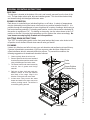
32:(5&25'
6:,7&+
62/(12,'9$/9(
63$5.02'8/(
3,/27%851(5
*+3*+3*+3*+3
7(50,1$/%/2&.237,21$/
5(9
'$7((&2
'(6&5,37,212)&+$1*(
'5
7+,6'5$:,1*&217$,16,1)250$7,21&21),'(17,$/7267$50)*,17/
,1&125(352'8&7,2125',6&/2685(2),76&217(176,63(50,77('
72/(5$1&(81/(66127('[[[
$1*/(6
5(9,6,216
3$5712
02'(/12
7,7/(
0$7(5,$/
),1,6+
67$50$18)$&785,1*,17(51$7,21$/,1&
6811(1'5,9(
67/28,60286$
'5
&.
'$7(
0:
:'*+3*DV+RW3ODWH
'-6
2M-W1662 Operation Manual - Lang Gas Countertop Range, GHP Series
2M-W1662 Operation Manual - Lang Gas Countertop Range, GHP Series

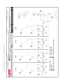
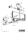
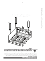
12
SK2493 Rev. - 3/04/11
Model:
GHP Gas Hotplate
See Detail
A
1
2
9
10
11
17
16
18
19
20
21
14
13
12
15
7
8
3
4
5
6
2M-W1662 Operation Manual - Lang Gas Countertop Range, GHP Series
2M-W1662 Operation Manual - Lang Gas Countertop Range, GHP Series

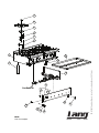
13
To
Burner
To Pilot
Detail A
SK2494 Rev. - 3/04/11
Model:
GHP Gas Hotplate Detail A
22
25
26
27
29
30
31
32
33
28
24
23
2M-W1662 Operation Manual - Lang Gas Countertop Range, GHP Series
2M-W1662 Operation Manual - Lang Gas Countertop Range, GHP Series

14
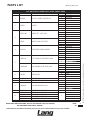
PARTS LIST.. . . . . . . March 29, 2011, Rev -
IMPORTANT: WHEN ORDERING, SPECIFY VOLTAGE OR TYPE GAS DESIRED PAGE 1
INCLUDE MODEL AND SERIAL NUMBER OF 3
Some items are included for illustrative purposes only and in certain instances may not be available.
GAS HOTPLATES, MODEL GHP2, GHP4, GHP6 & GHP8
Fig No Part Number.. Description Quantity. Application
1 2R-W1664 TOP CAP - DOMED, "INSTANT ON"
2 GHP4ODB
4 GHP8ODB
6 GHP6ODB
8 GHP8ODA
2 2F-Z0637 CASTING
2 GHP2
4 GHP4
6 GHP6
8 GHP8
3
2F-Z5473-W1 BURNER SET - CAST IRON
2 GHP2
4 GHP4
6 GHP6
8 GHP8
2I-Z5476 GASKET U-MAX HOTPLATES
2 GHP2
4 GHP4
6 GHP6
8 GHP8
4 T9-143-013 ASSY-INSTANT ON MECHANISM
1 GHP2ODB
2 GHP4ODB
4 GHP8ODB
6 GHP6ODB
8 GHP8ODA
5
2J-80201-24 PLT LT BURNR FR GEI12LEAD, FRONT
1 GHP2
2 GHP4
6 GHP6
4 GHP8
2J-80201-W31 PILOT BURNER R/H 36" LEAD, BACK
1 GHP2
2 GHP4
3 GHP6
4 GHP8
6 2F-W1666 VENTURI ASSY
2 GPP2
4 GHP4
6 GPP6
8 GHP8
7 T9-143-001 SIDE ASSY-LH 1 ALL
8 2A-72500-20 LEG 10.25 WITH ADJ HEX 4 ALL
9 2J-80300-03 SPRK IGNITR MODULE SM2
2 GHP2
4 GHP4
6 GHP6
8 GHP8
10 2E-30501-02 TRM STRP 3 POLE W/PUSH ON 1 ALL
11
T9-143-109 GREASE TRAY ASSY-GHP2
1
GHP2
T9-143-209 GREASE TRAY ASSY-GHP4 GHP4
T9-143-209 GREASE TRAY ASSY-GHP6 GHP6
T9-143-409 GREASE TRAY ASSY-GHP8 GHP8
12 T9-143-000 SIDE ASSY-RH 1 ALL
2M-W1662 Operation Manual - Lang Gas Countertop Range, GHP Series
2M-W1662 Operation Manual - Lang Gas Countertop Range, GHP Series

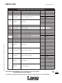
15
PARTS LIST.. . . . . . . March 29, 2011, Rev -
IMPORTANT: WHEN ORDERING, SPECIFY VOLTAGE OR TYPE GAS DESIRED PAGE 2
INCLUDE MODEL AND SERIAL NUMBER OF 3
Some items are included for illustrative purposes only and in certain instances may not be available.
GAS HOTPLATES, MODEL GHP2, GHP4, GHP6 & GHP8
Fig No Part Number.. Description Quantity. Application
14 2C-20602-04 TINNERMAN SPD NUT 1/8 DIA 2 ALL
15 K9-60301-43-1 DIE CAST PLT LANG SATIN, w/CLIPS 1 ALL
16 2M-W728-W2 LABEL - CONTROL OFF-HI-LO
2 GHP2
4 GHP4
6 GHP6
8 GHP8
17 2R-W498 KNOB-RED
2 GHP2
4 GHP4
6 GHP6
8 GHP8
18 2I-05-07-0013 BOOT SWITCH 1 ALL
19 2M-12-07-0038 LABEL ON & OFF 1 ALL
20 Z1-70-07-0343 SWITCH GUARD 1 ALL
21 2E-Z12020 SWITCH-TOGGLE 2P ST 1 ALL
22 T9-143-024 WELDMENT - FLEX TUBE 17" 1 ALL
23 2J-Z4686 REGULATOR-3/4 X 3/4 1 ALL
24 T9-143-020 REGULATOR BRACKET 2 ALL
25
2J-70101-104 FLEX GAS HOSE 17 X 3/4
1 GHP4, GHP6, GHP8
2 GHP2
2J-70101-105 FLEX GAS HOSE 31 X 3/4 1 GHP4, GHP6, GHP8
26 2K-70304-05 ELBOW, PIPE 90o ST 3/4 1 ALL
27 2V-80502-06 SLENOID VLVE 120VAC 3/4 1 ALL
28 2K-70308-01 PIPE PLUG REG 1/8 NPT BLK 1 ALL
29 2V-Z6939 VALVE HI-LO
2 GHP2
4 GHP4
6 GHP6
8 GHP8
30 2K-70101-W123 ADAPTER BRASS 1/8NPTF X
2 GHP2
4 GHP4
6 GHP6
8 GHP8
31 2A-W1185 ORIFICE FITTING - 90 DEG
2 GHP2
4 GHP4
6 GHP6
8 GHP8
32
2A-Z4931 ORIFIE #52 BLK
2 GHP2-LP
4 GHP4-LP
6 GHP6-LP
8 GHP8-LP
2A-Z5542 ORIFICE HOOD #37
2 GHP2-NAT
4 GHP4-NAT
6 GHP6-NAT
8 GHP8-NAT
2M-W1662 Operation Manual - Lang Gas Countertop Range, GHP Series
2M-W1662 Operation Manual - Lang Gas Countertop Range, GHP Series

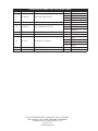
16
STAR INTERNATIONAL HOLDINGS INC. COMPANY
Star - Holman - Lang - Wells - Bloomeld - Toastmaster
10 Sunnen Drive, St. Louis, MO 63143 U.S.A.
(314) 781-2777
www.star-mfg.com
GAS HOTPLATES, MODEL GHP2, GHP4, GHP6 & GHP8
Fig No Part Number.. Description Quantity. Application
33 2V-70402-06 VALVE PILOT 1/8NPTX1/4CC
1 GHP1
2 GHP4
3 GHP6
4 GHP8
AR 2M-61133-W1 W/D GHP AR ALL
NI 2A-80401-02 PILOT BURNER ORIFICE .010
2 GHP2-LP
4 GHP4-LP
8 GHP8-LP
NI 2C-20119-01 EYEBLTFORGD/SHLDR1/4-20X1 1 ALL
NI 2E-31107-02-W2 CORDSET 14/3 15A 120V 10' 1 ALL
NI 2K-Y1139 BUSHING HEYCO SB500-6
1 GHP2
2 GHP4
3 GHP6
4 GHP8
NI 2M-60304-W1 LABEL-LIGHTING INST. 1 GHP8
NI 2M-61133-W1WL LABEL - W/D GHP 1 GHP8


10
Mode d'emploi
CUVETTE DE PROPRETÉ
La cuvette de propreté se trouve sous l'appareil et elle est facile à retirer par l'avant de celui-
ci. La cuvette recueille les déversements, les excédents et la graisse. Elle doit être vériée
quotidiennement et nettoyée avec un savon doux et de l'eau chaude.
UTILISATION DU BRÛLEUR
Il y a un bouton « marche », « feu vif », « feu doux » et « arrêt » pour chaque brûleur. En
plaçant le bouton dans toutes les positions entre « feu vif » et « feu doux », on obtient un
grand éventail de températures. Gâce à cette façon de procéder, il est possible d'avoir
un « feu vif » ou d'autres sélections de températures, en même temps qu'un « feu doux ».
Pour chauffer chaque section, tourner le bouton de la section désirée à l'envers des aiguilles
d'une montre jusqu'à la position « feu vif ». Pour réserver ou faire mijoter, placer le bouton
plus près de « feu doux ». Le choix de la chaleur est libre, il suft de placer les boutons en
conséquence. S'assurer que les brûleurs restent allumés quand ils sont à feu doux.
INSTRUCTIONS DE FERMETURE
Mettre l'interrupteur de la amme pilote à « Arrêt » sur le panneau de contrôle, fermer les
boutons de réglage pour éteindre les brûleurs et fermer le robinet de fermeture manuel du
gaz.
NETTOYAGE
Il faut très peu de temps et d'effort pour conserver l'apparence et l'efcacité maximale de
votre appareil. Si des dépôts de graisses s'accumulent, ils vont former un galet gommant
qui va ensuite carboniser et se
transformer en une substance dure qui
est très difcile à éliminer. Pour éviter
cette situation, nous vous suggérons les
étapes de nettoyage suivantes :
Nettoyer régulièrement, laisser refroidir
l'appareil.
Pour éliminer les particules de carbone,
enlever la grille et les têtes des brûleurs et
nettoyer dans l'évier avec un savon doux
et de l'eau chaude.
Le fond du brûleur et le tuyau venturi ne
doivent pas être en contact avec de la
graisse ou des matériaux inconnus.
Utiliser un chiffon propre et un bon nettoyant
non abrasif quotidiennement pour nettoyer
la surface en acier inoxydable de l'appareil.
Nettoyer dans le sens du grain avec un
chiffon doux.
Vider la cuvette de propreté au moins une
fois par jour et nettoyer comme tout autre
ustensile de cuisine. Retirer le tiroir en
tirant vers l'avant.
1.
2.
3.
4.
5.
IL2185-FR
Grille
Brûleur
Cuvette de propreté
Fond du brûleur
et tube de venturi
2M-W1662 Operation Manual - Lang Gas Countertop Range, GHP Series

9
INSTALLATION GÉNÉRALE (suite)
INSTRUCTIONS POUR LA FLAMME PILOTE
La gamme complète est équipée d'un allumeur automatique muni d'une étincelle
électronique.
S'assurer que tous les boutons de réglage du panneau de contrôle avant sont en position
« Arrêt ».
Ouvrir la conduite de gaz principale.
Allumer l'interrupteur sur le panneau de contrôle avant pour activer la amme pilote
électronique.
Les ammes pilotes ont été ajustées au moment de leur fabrication. Tourner les vis ajustables
dans le sens contraire des aiguilles d'une montre pour ouvrir et dans le sens des aiguilles pour
fermer.
Si nécessaire, ajuster les ammes pilotes le plus bas possible, mais assez fort pour que les
brûleurs s'allument immédiatement lorsque la valve est au plus fort.
Tourner les boutons à l'intensité souhaitée.
Pour
fermer les brûleurs, mettre les poignées à « OFF » et fermer l'interrupteur sur le panneau
de contrôle avant.
ALLUMAGE DU BRÛLEUR ET RÉGLAGES
Pour allumer un brûleur, tourner le bouton de réglage dans le sens contraire des aiguilles d'une
montre jusqu'à ce qu'il soit en position « Marche ».
Réduire doucement l'ouverture des obturateurs d'air pour obtenir une amme bleue au bout
lumineux. Ensuite, augmenter doucement l'ouverture jusqu'à ce que le jaune disparaisse et qu'il
ne reste qu'une amme bleue.
PREMIER ALLUMAGE
Lors du premier allumage, l'appareil produira de la fumée pendant environ 20 à 30 minutes,
jusqu'à ce que les huiles de protection et les impuretés dues au processus de fabrication
soient éliminées.
NE PAS UTILISER LORS D'UNE PANNE DE COURANT.
1.
2.
3.
4.
5.
6.
7.
1.
2.
2M-W1662 Operation Manual - Lang Gas Countertop Range, GHP Series
2M-W1662 Operation Manual - Lang Gas Countertop Range, GHP Series
La page charge ...
La page charge ...
La page charge ...
La page charge ...
La page charge ...
La page charge ...
La page charge ...
La page charge ...
-
 1
1
-
 2
2
-
 3
3
-
 4
4
-
 5
5
-
 6
6
-
 7
7
-
 8
8
-
 9
9
-
 10
10
-
 11
11
-
 12
12
-
 13
13
-
 14
14
-
 15
15
-
 16
16
-
 17
17
-
 18
18
-
 19
19
-
 20
20
-
 21
21
-
 22
22
-
 23
23
-
 24
24
-
 25
25
-
 26
26
-
 27
27
-
 28
28


Lang GHP2 Mode d'emploi
- Taper
- Mode d'emploi
- Ce manuel convient également à
dans d''autres langues
- English: Lang GHP2 Operating instructions