
Wattstopper
®
DLM - Infrared Receiver
Installation Instructions • Instructions d’Installation • Instrucciones de Instalación
No: 25096 – 10/16 rev. 1
Catalog Number • Numéro de Catalogue • Número de Catálogo: LMIR-100
Country of Origin: Made in China • Pays d’origine: Fabriqué en Chine • País de origen: Hecho en China
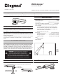
PLACEMENT GUIDELINES
The LMIR-100 provides an IR remote interface for DLM devices that
are not within line of sight of the user. It accepts commands from DLM
IR devices such as hand-held remote controls, and forwards them to
the DLM Local Network. Choose a place for the LMIR-100 that it is in
direct view of the user. Avoid obstruction by objects such as furniture or
partitions. It has a 360˚ 30-35 foot (10m) line of sight receiving range.
SPECIFICATIONS
Input Voltage ..................................................................... 24VDC
Current Consumption .............................................................5mA
Power Supply ................................. Wattstopper Room Controller
Connection to the DLM Local Network ...................... 1 RJ-45 port
DLM Local Network characteristics when using LMRC-11x/2xx
room controllers:
Low voltage power provided over Cat 5e cable (LMRJ);
max current 800mA. Supports up to 64 load addresses,
48 communicating devices including up to 4 LMRC-10x
series and/or LMPL-101 controllers.
Free topology up to 1,000’ max.
Environment ................................................. For Indoor Use Only
Operating Temperature .................32° to 131°F (0° to 55°C)
Storage Temperature ...................23° to 140°F (-5° to 60°C)
Relative Humidity .......................5 to 95% (non condensing)
Other:
RoHS compliant
Patent Pending
This unit is pre-set for Plug n’ Go™ operation, adjustment is optional.
For full operational details, adjustment and more features of the product, see the
DLM System Installation Guide provided with Wattstopper room controllers, and
also available at www.legrand.us/wattstopper.
Installation shall be in accordance with all applicable regulations, local and
NEC codes. Wire connections shall be rated suitable for the wire size (lead and
building wiring) employed.
For Class 2 DLM devices and device wiring: To be connected to a Class 2 power
source only. Do not reclassify and install as Class 1, or Power and Lighting
Wiring.
WARNING: DO NOT USE THE DLM SYSTEM TO
CONTROL LOADS OTHER THAN LIGHTING IF
THE LOAD IS NOT IN VIEW OF A PERSON AT ALL
CONTROL LOCATIONS. DO NOT USE DLM TO CONTROL
ANY LOAD THAT MIGHT BE DANGEROUS OR CAUSE A
HAZARDOUS SITUATION IF ACCIDENTALLY ACTIVATED.
32’
(10m)
ceiling
height
40°
32’
MOUNTING THE RECEIVER
The device has an adjustable head to accommodate multiple mounting
methods and building materials or fixture walls up to 5/8” thickness.
0” - 0.5” adjustable
for mounting material
Ceiling or fixture wall
ATTACHING THE LMRJ CABLE

800.879.8585
www.legrand.us/wattstopper
No. 25096 – 10/16 rev. 1
© Copyright 2016 Legrand All Rights Reserved.
© Copyright 2016 Tous droits réservés Legrand.
© Copyright 2016 Legrand Todos los derechos reservados.
Wattstopper warranties its products to be free
of defects in materials and workmanship for a
period of five (5) years. There are no obligations
or liabilities on the part of Wattstopper for
consequential damages arising out of, or in
connection with, the use or performance of this
product or other indirect damages with respect
to loss of property, revenue or profit, or cost of
removal, installation or reinstallation.
Wattstopper garantit que ses produits sont
exempts de défauts de matériaux et de fabrication
pour une période de cinq (5) ans. Wattstopper
ne peut être tenu responsable de tout dommage
consécutif causé par ou lié à l’utilisation ou
à la performance de ce produit ou tout autre
dommage indirect lié à la perte de propriété, de
revenus, ou de profits, ou aux coûts d’enlèvement,
d’installation ou de réinstallation.
Wattstopper garantiza que sus productos
están libres de defectos en materiales y mano
de obra por un período de cinco (5) años. No
existen obligaciones ni responsabilidades por
parte de Wattstopper por daños consecuentes
que se deriven o estén relacionados con el
uso o el rendimiento de este producto u otros
daños indirectos con respecto a la pérdida
de propiedad, renta o ganancias, o al costo
de extracción, instalación o reinstalación.
WARRANTY INFORMATION INFORMATIONS RELATIVES À LA GARANTIE INFORMACIÓN DE LA GARANTÍA
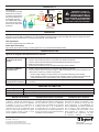
CONNECTIVITY
The LMIR-100
communicates to all other
DLM devices connected
to the DLM Local Network.
Connection drawings are
for example only. The
low voltage LMRJ cables
can connect to any DLM
device with an open RJ45
receptacle.
OPERATION
The LMIR-100 communicates to all other Lighting Management devices connected to the DLM Local Network. Mount the device
and connect it to the DLM Local Network. For use with DLM IR handheld remotes. When the LMIR-100 receives a signal from an IR
handheld remote and transmits it on the DLM Local Network, its red LED blinks.
Unit Adjustment
There are no adjustments on the LMIR-100.
Power Up Functionality:
Upon power up the device is ready to receive signals from any of the DLM IR handheld remotes.
TROUBLESHOOTING
Lights do not respond to IR handheld remote as expected.
Red LED on LMIR-100
blinks but load doesn’t
switch
1. Make sure nothing is blocking the line of sight between the handheld remote and LMIR-100.
2. Check to see that the the device is connected to the DLM Local Network.
3. Check to see that the IR handheld remote has batteries and that they are good.
4. Make sure the system is not in PnL.
5. Check load connections to room controllers and/or plug load controllers.
Red LED on LMIR-100
does NOT blink
1. Check to see that the the device is connected to the DLM Local Network.
2. Check for 24VDC input to the device: Plug in a different DLM device at the device location. If the
device does not power up, 24VDC is not present.
• Check the high voltage connections to the room controller and/or plug load controller.
• If high voltage connections are good and high voltage is present, recheck DLM Local Network
connections between the device and the room controller and/or plug load controller.
The wrong lights and/or
plug loads are controlled
1. Configure the IR handheld remote to control the desired loads using the Push n’ Learn adjustment
procedure.
ORDERING INFORMATION
Catalog Number Description
LMIR-100 Digital IR ceiling mount receiver
LMRH-102 Digital IR handheld 2-button remote control
Loads
1
2
Line Voltage
Room
Controller
J-Box
Occupancy
Sensor
Switch
LMIR-100
Infrared Receiver
LMRJ Cables
CAUTION: TO CONNECT A
COMPUTER TO THE DLM LOCAL
NETWORK USE THE LMCI-100.
NEVER CONNECT THE DLM
LOCAL NETWORK TO AN ETHERNET
PORT – IT MAY DAMAGE COMPUTERS
AND OTHER CONNECTED EQUIPMENT.
-
 1
1
-
 2
2

