Falmec FPMEX36I6SS Le manuel du propriétaire
- Catégorie
- Hottes
- Taper
- Le manuel du propriétaire

EN INSTRUCTIONS BOOKLET
IT LIBRETTO ISTRUZIONI
FR MODE D'EMPLOI
ES MANUAL DE INSTRUCCIONES
Mercurio
Mercurio XL
island
FPMER36I3SS
FPMEX36I6SS
FPMEX42I6SS

2
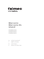
2 3/4" - 70 mm
23 5/8" - 600 mm
12 5/8" - 320 mm
max 22 1/2" - 572 mm
12 1/2" - 318 mm
10" - 255 mm
10 1/8"
258 mm
max 48 7/8" - 1242 mm
4 3/4"
121 mm
35 3/8" - 898 mm
21 5/8" - 550 mm
2 3/4" - 70 mm
23 5/8" - 600 mm
12 5/8" - 320 mm
max 22 1/2" - 572 mm
12 1/2" - 318 mm
10" - 255 mm
10 1/8"
258 mm
max 48 7/8" - 1242 mm
4 3/4"
121 mm
41 3/4" - 1060 mm
21 5/8" - 550 mm
280
cfm
EN- cable length 4 ft (1,2m)
FR- longueur de câble 4 ft (1,2m)
ES- longueur de câble 4 ft (1,2m)
IT- lunghezza cavo 4 ft (1,2m)
ø 6 1/4"
160 mm
3" - 75 mm
2 3/4" - 70 mm
10 1/8" - 265 mm
4 3/8"
110 mm
ø 4 3/4"
120 mm
12 1/2" - 316 mm
11 1/4" - 285,4 mm
7 7/8" - 200 mm
10" - 254,2 mm
ø 1/4" - 6 mm
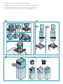
MERCURIO ISLAND 36" - Cod.: FPMER36I3SS
EN -
Side outlet which can only be used with false ceiling.
FR -
Sortie latérale utilisable uniquement avec faux-plafond.
ES -
Salida lateral utilizable solo con falso techo.
IT -
Uscita laterale utilizzabile solo con controsotto.
61 lb
28 kg
120Vac 60Hz 300W

3
3" - 75 mm
2 3/4" - 70 mm
10 1/8" - 265 mm
4 3/8"
110 mm
ø5 7/8"
150 mm
ø 6 1/4"
160 mm
12 1/2" - 316 mm
11 1/4" - 285,4 mm
7 7/8" - 200 mm
10" - 254,2 mm
ø 1/4" - 6 mm
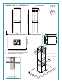
2 3/4" - 70 mm
23 5/8" - 600 mm
12 5/8" - 320 mm
max 22 1/2" - 572 mm
12 1/2" - 318 mm
10" - 255 mm
10 1/8"
258 mm
max 48 7/8" - 1242 mm
4 3/4"
121 mm
35 3/8" - 898 mm
21 5/8" - 550 mm
2 3/4" - 70 mm
23 5/8" - 600 mm
12 5/8" - 320 mm
max 22 1/2" - 572 mm
12 1/2" - 318 mm
10" - 255 mm
10 1/8"
258 mm
max 48 7/8" - 1242 mm
4 3/4"
121 mm
41 3/4" - 1060 mm
21 5/8" - 550 mm
600
cfm
EN- cable length 4 ft (1,2m)
FR- longueur de câble 4 ft (1,2m)
ES- longueur de câble 4 ft (1,2m)
IT- lunghezza cavo 4 ft (1,2m)
61 lb
28 kg
MERCURIO ISLAND XL 36" - Cod.: FPMEX36I6SS
EN -
Side outlet which can only be used with false ceiling.
FR -
Sortie latérale utilisable uniquement avec faux-plafond.
ES -
Salida lateral utilizable solo con falso techo.
IT -
Uscita laterale utilizzabile solo con controsotto.
120Vac 60Hz 430W

4
3" - 75 mm
2 3/4" - 70 mm
10 1/8" - 265 mm
4 3/8"
110 mm
ø5 7/8"
150 mm
ø 6 1/4"
160 mm
12 1/2" - 316 mm
11 1/4" - 285,4 mm
7 7/8" - 200 mm
10" - 254,2 mm
ø 1/4" - 6 mm
2 3/4" - 70 mm
23 5/8" - 600 mm
12 5/8" - 320 mm
max 22 1/2" - 572 mm
12 1/2" - 318 mm
10" - 255 mm
10 1/8"
258 mm
max 48 7/8" - 1242 mm
4 3/4"
121 mm
35 3/8" - 898 mm
21 5/8" - 550 mm
2 3/4" - 70 mm
23 5/8" - 600 mm
12 5/8" - 320 mm
max 22 1/2" - 572 mm
12 1/2" - 318 mm
10" - 255 mm
10 1/8"
258 mm
max 48 7/8" - 1242 mm
4 3/4"
121 mm
41 3/4" - 1060 mm
21 5/8" - 550 mm
EN- cable length 4 ft (1,2m)
FR- longueur de câble 4 ft (1,2m)
ES- longueur de câble 4 ft (1,2m)
IT- lunghezza cavo 4 ft (1,2m)
MERCURIO ISLAND XL 42" - Cod.: FPMEX42I6SS
EN -
Side outlet which can only be used with false ceiling.
FR -
Sortie latérale utilisable uniquement avec faux-plafond.
ES -
Salida lateral utilizable solo con falso techo.
IT -
Uscita laterale utilizzabile solo con controsotto.
600
cfm
67 lb
31 kg
120Vac 60Hz 430W

5
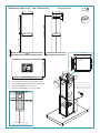
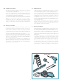
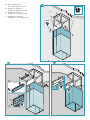
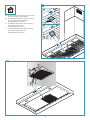
EN - Preliminary operations: separate upper trellis from lower trellis (1).
Filter removal (2).
FR -
Opérations préliminaires:
séparer le rail supérieur du rail inférieur (1).
Retrait des ltres (2).
ES - Operaciones preliminares: separar la estructura superior de la
estructura inferior (1). Extracción de ltros (2).
IT - Operazioni preliminari: separare traliccio superiore da traliccio infe-
riore (1). Rimozione ltri (2).
V2 (x8)
T
T1
1
1
3
1 2
2

6
ø1/4" - 8 mm
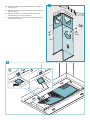
EN - Installation measurements
Recommended mounting height from cooking surface to hood bottom
is indicated by "A" in the drawing below.
It is recommended to install the hood in this range to optimize perfor-
mance. It is recommended to not exceed 35” (890mm) for dimension “A”
as hoods mounted above this may be dicult to reach for average height
users and performance and eciency will degrade.
Hoods mounted below the lower measurement in the “A” recommenda-
tion could result in damage due to heat and present a re hazard and
would avoid any warranty claims attributable to the lower mounting po-
sition.
If available, also refer to the cooking appliance manufacturer’s height
clearance recommendations and adhere to national and local building
and re codes which supersede any recommendations stipulated herein.
FR - Mesures pour installation
La hauteur de montage recommandée entre la surface de cuisson et la
partie inférieure de la hotte est indiquée par le « A » dans le dessin ci-des-
sous.
Il est recommandé d’installer la hotte dans cette plage pour optimiser
sa performance. Il est recommandé de ne pas dépasser les 890 mm (35
po) pour la dimension « A », car les hottes montées à une distance au-
dessus peuvent être diciles à atteindre pour les utilisateurs de hauteur
moyenne, et cela diminuera leur performance et ecacité.
Les hottes montées en-dessous de la mesure inférieure de la recomman-
dation « A » pourraient s’abîmer par la chaleur et présenter un risque
d’incendie, ce qui annulerait toute réclamation de garantie attribuable à
la position de montage inférieure.
Le cas échéant, reportez-vous également aux recommandations du
fabricant de l’appareil de cuisson en ce qui a trait au dégagement en
hauteur et respectez les codes du bâtiment et de prévention des incen-
dies nationaux et locaux qui remplacent toutes les recommandations
stipulées dans le présent document.
ES - Medidas instalación
La altura de montaje recomendada desde la supercie de cocción hasta
el fondo de la campana se indica con una "A" en el dibujo siguiente.
Se recomienda instalar la campana en este rango para optimizar el rendi-
miento. Se recomienda no exceder 35" (890mm) para la dimensión "A" ya
que las campanas montadas por encima de ésta pueden ser difíciles de
alcanzar para los usuarios de altura media y el rendimiento y la eciencia
se degradarán.
Las campanas montadas por debajo de la medida inferior de la recomen-
dación "A" podrían resultar dañadas por el calor y presentar un riesgo de
incendio, y evitarían cualquier reclamación de garantía atribuible a la po-
sición de montaje inferior.
Si está disponible, consulte también las recomendaciones de altura del
fabricante del equipo de cocina y respete los códigos de construcción y
contra incendios, nacionales y locales, que sustituyen cualquier recomen-
dación estipulada en el presente documento.
IT - Misure per l'installazione
L’altezza di montaggio consigliata tra il piano cottura e la parte inferiore
della cappa è indicata dalla lettera “A” nella gura sottostante.
Per ottenere prestazioni ottimali, si raccomanda di installare la cappa en-
tro i limiti, massimo e minimo, mostrati nella gura. È consigliabile che le
dimensioni di “A” non superino i 35” (890mm) in quanto le cappe monta-
te più in alto potrebbero presentare un livello ridotto di rendimento ed
ecienza, oltre a risultare dicili da raggiungere da parte degli utenti di
altezza media.
Al contrario, le cappe montate al di sotto dell’altezza minima consigliata
in “A” potrebbero danneggiarsi per il calore proveniente dal piano cottura
e presentare un rischio di incendio. Si ricorda che la garanzia non rispon-
de di eventuali danni derivanti da un montaggio in posizione troppo bas-
sa.
Se disponibile, fare riferimento anche all’altezza libera raccomandata dal
produttore del piano cottura. In ogni caso, è sempre necessario rispettare
le norme edilizie e antincendio in vigore, a livello sia nazionale sia locale,
le quali prevalgono su qualsiasi raccomandazione contenuta nel presen-
te.

7
H1
2 3/4" - 70 mm
A
H
CEILING
1
H1
2 3/4" - 70 mm
H
A
CEILING
FALSE CEILING
1
H1
H
A
CEILING
1
2 3/4" - 70 mm
H1
2 3/4" - 70 mm
A
H
CEILING
1
H1
2 3/4" - 70 mm
H
A
CEILING
FALSE CEILING
1
H1
H
A
CEILING
1
2 3/4" - 70 mm
H1
2 3/4" - 70 mm
A
H
CEILING
1
H1
2 3/4" - 70 mm
H
A
CEILING
FALSE CEILING
1
H1
H
A
CEILING
1
2 3/4" - 70 mm
3
4 5
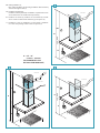
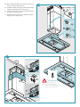
EN - Ceiling installation (3),
false ceiling installation (4) and ceiling installation without chimney
extension and upper trestle (5).
FR - Installation au plafond (3),
installation sur faux-plafond (4) et installation au plafond sans exten-
sion de cheminée et sans rail de ixation supérieure (5).
ES - Instalación en el techo (3), instalación en el contratecho (4) e instala-
ción en el techo sin extensión de chimenea y poste superior (5).
IT - Installazione a soitto (3), installazione a controsoitto(4) e installazio-
ne a soitto senza prolunga camino e traliccio superiore (5).
A = 24" - 35"
610 mm - 890 mm
(RECOMMENDED FOR
OPTIMAL PERFORMANCE)

8
Ø1/4" - 8 mm
x4
4
3
1
2
2
x8
1
H1
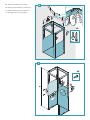
EN - Trestle (6) and extension (7) assembly.
FR -
Montage support de xation (6) et rallonge (7).
ES - Montaje estructura (6) y prolongación (7).
IT Montaggio traliccio (6) e prolunga (7).
6
7

9
T1
V1
3
2
T1
SP
1
V4 (x8)
H1
Ø1/4" - 8 mm
V1 (x4)
8
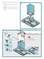
EN - Ceiling mount without upper trestle and without extension (8).
FR - Installation sur plafond sans support de xation supérieur et sans rallonge (8).
ES - Instalación en techo sin estructura superior y sin prolongación (8).
IT Installazione a sotto senza traliccio superiore e senza prolunga (8).

10
5 7/8"
150mm
4 3/4"
122mm
280
cfm
600
cfm
10
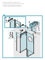
EN - Check valve assembly (9); exhaust pipe (10); chimney assembly (11).
FR - Montage clapet anti-retour (9); tube d’aspiration (10); assemblage conduit d’évacuation (11).
ES - Montaje de válvula de no retorno (9); tubo de aspiración (10); montaje de chimenea (11).
IT Montaggio valvola di non ritorno (9); tubo aspirazione (10); assemblaggio camino (11).
11
4
2
M
ERM
ERM
3
5
6
1
9

11
CEILING
2
V3 (x4)
1
2
2
FALSE CEILING
V4 (x8)
1
3
V3 (x4)
2
FALSE CEILING
CONTROSOFFIT
TO
3
V3 (x4)
12
13 14
EN - Ceiling conguration (12);
False ceiling conguration (13)(14).
FR - Installation sur plafond (12);
Installation sur faux-plafond (13)(14).
ES - Conguración en techo (12);
Conguración en falso techo (13)(14).
IT - Congurazione a sotto (12);
Congurazione a controsotto (13)(14).

12
1
6
5
V3 (x4)
2
V3 (x4)
3
4
V6 (x2)
EN - Motor chamber installation (15); electrical connection and
chimney + extension installation (16).
FR - Installation chambre moteur (15); branchement électrique
et xation conduit d’évacuation + rallonge (16).
ES - Instalación cámara motor (15); conexión eléctrica y jación
de chimenea + prolongación (16).
IT - Installazione camera motore (15); collegamento elettrico e
ssaggio camino + prolunga (16).
1
V5 (x4)
2B
2A
V5 (x4)
16
15
EN - Mandatory safety screws
FR - Vis de sécurité obligatoires
ES - Tornillos de seguridad obligatorios
IT - Viti di sicurezza obbligatorie

13
G
G
T1
F
1
V5 (x4)
2B
2A
V5 (x4)
V6 (x2)
17
18
EN - Installation on ceiling without extension (H) and trellis (T)
(17) (18).
FR - Installation au plafond sans rallonge (H) ni treillis (T)
(17) (18).
ES - Instalación en techo sin extensión (H) y enrejado (T)
(17) (18).
IT Installazione su sotto senza prolunga (H) e traliccio (T)
(17) (18).
EN - Mandatory safety screws
FR - Vis de sécurité obligatoires
ES - Tornillos de seguridad obligatorios
IT - Viti di sicurezza obbligatorie

14
1
2
2
20
EN - How to uninstall: remove panel (19), remove metal
lters (20). Assembly of optional lter
FR - Procédure de désinstallation : déposer le panneau
(19), enlever les ltres métalliques (20).
Montage du ltre en option (22).
ES - Procedimiento de desmontaje: quite el panel (19),
quite los ltros metálicos (20).
Montaje del ltro opcional (22).
IT - Procedura di disinstallazione: rimuovere pannello
(19), rimuovere ltri metallici (20).
Montaggio ltro opzionale (22).
3
2
1
19

15
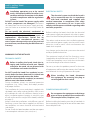
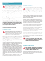
SAFETY INSTRUCTIONS
AND WARNINGS
Installation operations are to be carried
out by skilled and qualied installers in ac-
cordance with the instructions in this book-
let and in compliance with the regulations
in force.
DO NOT use the hood if the power supply cable
or other components are damaged: disconnect
the hood from the electrical power supply and con-
tact the Dealer or an authorised Servicing Dealer for
repairs.
Do not modify the electrical, mechanical or
functional structure of the equipment.
Do not personally try to carry out repairs or
replacements. Interventions carried out by
incompetent and unauthorised persons can
cause serious damage to the unit or physical and
personal harm, not covered by the Manufacturer's
warranty.
WARNINGS FOR THE INSTALLER
TECHNICAL SAFETY
Before installing the hood, check the in-
tegrity and function of each part. Should
anomalies be noted, do not proceed with
installation and contact the Dealer.
Do NOT install the hood if an aesthetic (or cos-
metic) defect has been detected. Put it back into
its original package and contact the dealer.
No claim can be made for aesthetic (or cosmetic)
defects once it has been installed.
During installation, always use personal protective
equipment (e.g.: Safety shoes) and adopt prudent
and proper conduct.
The installation kit (screws and plugs) supplied with
the hood is only to be used on masonry walls: in case
of installation on walls of a dierent material, assess
other installation options keeping in mind the type
of wall surface and the weight of the hood (indicated
on page 2).
Keep in mind that installations with dierent types of
fastening systems from those supplied, or which are
not compliant, can cause electrical and mechanical
seal danger.
Do not install the hood outdoors and do not expose
it to atmospheric elements (rain, wind, etc.).
ELECTRICAL SAFETY
The electrical system to which the hood is
to be connected must be in accordance
with local standards and supplied with
earthed connection in compliance with safety
regulations in the country of use. It must also
comply with European standards regarding radio
antistatic properties.
Before installing the hood, check that the electrical
mains power supply corresponds with what is report-
ed on the identication plate located inside the hood.
The socket used to connect the installed equipment
to the electrical power supply must be within reach:
otherwise, install a mains switch to disconnect the
hood when required.
Any changes to the electrical system must be carried
out by a qualied electrician.
The maximum length of the ue fastening screws
(supplied by the manufacturer) must be 1/2" (13 mm).
Use of non-compliant screws with these instructions
can lead to danger of an electrical nature.
Do not try to solve the problem yourself in the event
of equipment malfunction, but contact the Dealer or
an authorised Servicing Department for repairs.
When installing the hood, disconnect
the equipment by removing the plug or
switching o the main switch.
FUMES DISCHARGE SAFETY
Do no connect the equipment to discharge
pipes of fumes produced from combustion
(for example boilers, replaces, etc.).
Before installing the hood, ensure that all standards in
force regarding discharge of air out of the room have
been complied with.

16
USER WARNINGS
These warnings have been drawn up for
your personal safety and those of others.
You are therefore kindly asked to read the
booklet carefully in its entirety before using the
or cleaning the equipment.
The Manufacturer declines all responsibility for
any damage caused directly, or indirectly, to per-
sons, things and pets as a consequence of failing
to comply with the safety warnings indicated in
this booklet.
It is imperative that this instructions booklet is
kept together with the equipment for any future
consultation.
If the equipment is sold or transferred to another per-
son, make sure that the booklet is also supplied so
that the new user can be made aware of the hood's
operation and relative warnings.
After the stainless steel hood has been installed, it
will need to be cleaned to remove any residues re-
maining from the protection adhesive as well as any
grease and oil stains which, if not removed, can cause
irreversible damage to the hood surface. To properly
clean the unit, the manufacturer recommends using
the supplied moist wipes, which are also available
sold separately.
Insist on original spare parts.
State of California Proposition 65 Warning
(US only)
WARNING
This product contains chemicals known to the State
of California to cause cancer and birth defects or oth-
er reproductive harm.
For more information go to www.P65Warnings.ca.gov
INTENDED USE
The equipment is solely intended to be used to
extract fumes generated from cooking food in
non-professional domestic kitchens: any other
use is improper. Improper use can cause damage
to persons, things, pets and exempts the Manu-
facturer from any liability.
The equipment can be used by children over the age
of 8 and by persons with reduced physical, sensory
and mental abilities, or with no experience or knowl-
edge, as long as they do so under supervision or after
having received relative instructions regarding safe
use of the equipment and understanding of the dan-
gers connected to it.
Children are not to play with the equipment. Clean-
ing and maintenance by the user must not be carried
out by children without supervision.
USE AND CLEANING WARNINGS
Before cleaning or carrying out mainte-
nance operations, disconnect the equip-
ment by removing the plug or switching
o the main switch.
Do not use the hood with wet hands or bare feet.
Always check that all electrical parts (lights, extractor
fan) are o when the equipment is not being used.
The maximum overall weight of any objects placed
or hung (if applicable) on the hood must not exceed
3lb 5 oz (1.5 Kg).
Always supervise the cooking process during the use
of deep-fryers: Overheated oil can catch re.
Do not leave open, unattended ames under the
hood.
Do not prepare food over an open ame under the
hood.
Never use the hood without the metal anti-grease
lters: in this case, grease and dirt will deposit in the
equipment and compromise its operation.
Accessible parts of the hood can be hot when used at
the same time as the cooking appliances.
Do not carry out any cleaning operations when parts
of the hood are still hot.
There can be a risk of re if cleaning is not carried out
according to the instructions and products indicated
in this booklet.
Disconnect the main switch when the equipment is
not used for long periods of time.
If other appliances that use gas or other fu-
els are being used at the same time (boiler,
stove, replaces, etc.), make sure the room
where the fumes are discharged is well-ven-
tilated, in compliance with the local regula-
tions.

17
ENGLISH
INSTALLATION
only intended for qualied personnel
Before installing the hood,
carefully read the chapter
'SAFETY INSTRUCTIONS AND WARNINGS'.
TECHNICAL FEATURES
The technical specications are exhibited on the labels located inside
the hood.
POSITIONING
The minimum distance between the highest part of the cooking
equipment and the lowest part of the hood is indicated in the in-
stallation instructions.
Do not install the hood outdoors and do not expose it to outdoor envi-
ronment (rain, wind, etc.).
ELECTRICAL CONNECTION
(only intended for qualied personnel)
Disconnect the equipment from electrical mains power
supply before carrying out any operations on the hood.
Ensure that the wires inside the hood are not disconnected
or cut:
in the event of damage, contact your nearest Servicing Department.
Refer to qualied personnel for electrical connections.
Connection must be carried out in compliance with the provisions
of law in force.
Before connecting the hood to the electrical mains power supply,
check that:
• voltage supply corresponds with what is reported on the data plate
located inside the hood;
• the electrical system is compliant and can withstand the load (see
the technical specications located inside the hood);
• the power supply plug and cable do not come into contact with
temperatures exceeding 158°F (70 °C);
• the power supply system is eectively and properly connected to
earth in compliance with regulations in force;
• the socket used to connect the hood is within reach.
In case of:
• devices tted with cables without a plug: the type of plug to use is
a ''standardised'' one. The wires must be connected as follows: yel-
low-green for earthing, blue for neutral and brown for the phase. The
plug must be connected to an adequate safety socket.
• xed equipment not provided with a power supply cable and plug,
or any other device that ensures disconnection from the electrical
mains, with an opening gap of the contacts that enables total dis-
connection in overvoltage category III conditions.
Said disconnection devices must be provided in the mains power
supply in compliance with installation regulations.
The yellow/green earth cable must not be cut o by the switch.
The Manufacturer declines all responsibility for failure to comply with
the safety regulations.
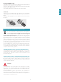
FUMES DISCHARGE
EXTERNAL EXHAUST HOOD (SUCTION)
In this version the fumes and vapours are discharged
outside through the exhaust pipe.
To this end, the hood outlet tting must be connected
via a pipe, to an external output.
The outlet pipe must have:
• a diameter not less than that of the hood tting.
• a slight slope downwards (drop) in the horizontal sections to prevent
condensation from owing back into the motor.
• the minimum required number of bends.
• the minimum required length to avoid vibrations and reduce the
suction performance of the hood.
You are required to insulate the pipes if it passes through cold envi-
ronments.
In the presence of motors with 500CFM or higher, a check valve is
present to prevent external air owing back.
HOOD WITH INTERNAL RECIRCULATION (ltering)
In this model, the air passes through the charcoal lters
to be puried and recycled in the environment.
Ensure that the active carbon lters are assembled into
the hood, if not, install them as indicated in the assem-
bly instructions.
In this version the check valve must not be assembled: remove
it if it is on the air outlet tting of the motor.
ASSEMBLY INSTRUCTIONS
only intended for personnel qualied
The hood can be installed in various congurations.
The generic assembly steps apply to all installations; for
each case, follow the specic steps provided for the re-
quired installation.
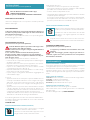
OPERATION
WHEN TO TURN ON THE HOOD?
Switch on the hood at least one minute before starting to cook to direct
fumes and vapours towards the suction surface.
After cooking, leave the hood operating until complete extraction of all
vapours and odours. By means of the Timer function, it is possible to set
auto switch-o function which will allow the hood to turn o automat-
ically after 15 minutes of operation.
WHICH SPEED IS TO BE SELECTED?
1st speed: maintains the circulation of clean air with low electricity
consumption.
2nd speed: normal conditions of use.
3rd speed: presence of strong odours and vapours.
4th speed: rapid disposal of odours and vapours.
WHEN SHOULD THE FILTERS BE WASHED OR REPLACED?
The metal lters must be cleaned every 30 hours of operation.
The active carbon lters must be replaced every 3-4 months, depend-
ing on the use of the hood.
For further details see the “MAINTENANCE” chap.

18
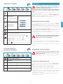
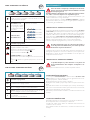
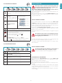
ELECTRONIC PUSHBUTTON PANEL
Motor ON/OFF
Upon start-up, the speed is that stored at the previous op-
eration.
Increase speed from 1 to 4
Speed 4 is only active for a
few minutes, then speed 3
activates.
The speeds are indicated by
the LEDs on the keys:
Speed 1
Speed 2
Speed 3
Speed 4
("+" LED ashing)
Reduce speed from 4 to 1
Light on/o
TIMER (red LED ashing)
Auto switch-o after 15 min.
The function deactivates (red LED o) if:
- The TIMER key ( ) is pressed again.
- The ON/OFF key (
) is pressed.
FILTER ALARM (red LED steady on with (
) o)
Anti-grease lter maintenance after approximately 30 hours
of operation.
Press (
) the meter for 3 seconds to reset.
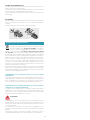
USE OF MECHANICAL PUSH BUTTON
CONTROL PANEL
OFF 1 2 3
Light on/o
OFF
OFF button
Press this button to switch the motor o
1
Button 1: Press this button (button in) to start or set
the motor at minimum speed
2
Button 2: Press this button (button in) to start
or set the motor at medium speed
3
Button 3: Press this button (button in) to start or
set the motor at maximum speed
600
cfm
280
cfm
MAINTENANCE
Before cleaning or carrying out maintenance operations,
disconnect the equipment by removing the plug or
switching o the main switch.
Do not use detergents containing abrasive, acidic or corrosive
substances or abrasive cloths.
Regular maintenance guarantees proper operation and performance
over time.
Special attention is to be paid to the metal anti-grease lters : fre-
quent cleaning of the lters and their supports ensures that no amma-
ble grease is accumulated.
CLEANING OF EXTERNAL SURFACES
You are advised to clean the external surfaces of the hood at least once
every 15 days to prevent oily substances and grease from sticking to
them. To clean the brushed stainless steel hood, the Manufacturer rec-
ommends using "Magic Steel" wipes.
Alternatively and for all the other types of surfaces, it can be cleaned
using a damp cloth, slightly moistened with mild, liquid detergent or
denatured alcohol.
Complete cleaning by rinsing well and drying with soft cloths.
Do not use too much moisture or water around the push
button control panel and lighting devices in order to pre-
vent humidity from reaching electronic parts.
The glass panels can only be cleaned with specic, non-corrosive or
non-abrasive detergents using a soft cloth.
The Manufacturer declines all responsibility for failure to comply with
these instructions.
CLEANING OF INTERNAL SURFACES
Do not clean electrical parts, or parts related to the motor
inside the hood, with liquids or solvents.
For the internal metal parts, see the previous paragraph.
METAL ANTI-GREASE FILTERS
It is advised to frequently wash the metal lters (at least once a
month) leaving them to soak in boiling water and cleaning solution for
1 hour, taking care not to bend them.
Do not use corrosive, acid or alkaline detergents.
Rinse them well and wait for them to be completely dry before reas-
sembling them.
Washing in a dishwasher is permitted, however, it may cause the lter
material to darken: to reduce the possibility of this problem from hap-
pening, use low-temperature washes 131°F (55°C max.).
To extract and insert the metal anti-grease lters see the assembly in-
structions.

19
ENGLISH
ACTIVE CARBON FILTERS
These lters retain the odours in the air that passes through them. The
puried air is recirculated into the environment.
The active carbon lters must be replaced on average every 3-4 months
under normal conditions of use.
See assembly instructions to replace the active carbon lters.
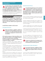
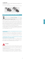
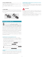
LIGHTING
The range hood is equipped with high eciency, low consumption
LED spotlights with an extremely long life-span under normal use con-
ditions.
Should the LED spotlight need to be replaced, proceed as shown in
the gure.
12V
3
1
2
DISPOSAL AFTER END OF USEFUL LIFE
The crossed-out trash or refuse bin symbol on the appliance
means that the product is WEEE, i.e. “Waste electrical and
electronic equipment'', accordingly it must not be disposed
of with regular unsorted waste (i.e. with ''mixed household waste''),
but it must be disposed of separately so that it can undergo specic
processing for its re-use, or a specic treatment, to remove and safely
dispose of any substances that may be harmful to the environment and
remove the raw materials that can be recycled. Proper disposal of these
products contributes to saving valuable resources and avoid potential
negative eects on personal health and the environment, which may
be caused by inappropriate disposal of waste.
You are kindly asked to contact your local authorities for further infor-
mation regarding the designated waste collection points nearest to
you. Penalties for improper disposal of such waste can be applied in
compliance with national regulations.
INFORMATION ON DISPOSAL IN EUROPEAN UNION COUNTRIES
The EU WEEE Directive was implemented dierently in each country,
accordingly, if you wish to dispose of this appliance we suggest con-
tacting your local authorities or dealer to nd out what the correct
method of disposal is.
INFORMATION ON DISPOSAL IN NON-EUROPEAN UNION COUNTRIES
The crossed-out trash or refuse bin symbol is only valid in the European
Union: if you wish to dispose of this appliance in other countries, we
suggest contacting your local authorities or dealer to nd out what the
correct method of disposal is.
WARNING!
The Manufacturer reserves the right to make changes to the equip-
ment at any time and without prior notice. Printing, translation and
reproduction, even partial, of this manual are bound by the Manufac-
turer's authorisation.
Technical information, graphic representations and specications in
this manual are for information purposes and cannot be divulged.
This manual is written in Italian. The Manufacturer is not responsible for
any transcription or translation errors.

20
CONSIGNES DE SÉCURITÉ
ET MISES EN GARDE
Le travail d'installation doit être eectué
par des installateurs compétents et quali-
és, conformément aux indications du pré-
sent manuel et en respectant les normes
en vigueur.
Si le câble d'alimentation ou d’autres composants
sont endommagés, la hotte NE doit PAS être utili-
sée: débrancher la hotte de l'alimentation électrique
et contacter le revendeur ou un Centre d’Assistance
technique agréé pour la réparation.
Ne pas modier la structure électrique, méca-
nique et fonctionnelle de l'appareil.
Ne pas tenter d'eectuer soi-même des répara-
tions ou des remplacements : les interventions
eectuées par des personnes non compétentes
et non qualiées peuvent provoquer des dom-
mages, éventuellement très graves, à des choses
et/ou à des personnes, non couverts par la garan-
tie du Fabricant.
MISES EN GARDE POUR L’INSTALLATEUR
SÉCURITÉ TECHNIQUE
Avant d'installer la hotte, contrôler l'inté-
grité et la fonctionnalité de chaque partie:
en cas de constatation d'anomalies, ne pas
procéder à l'installation et contacter le Re-
vendeur.
En cas de constatation d'un défaut esthétique, la
hotte NE doit PAS être installée; la remettre dans
son emballage d’origine et contacter le Reven-
deur.
Après son installation, aucune réclamation ne
sera acceptée pour des défauts esthétiques.
Pendant l'installation, toujours utiliser des équipe-
ments de protection individuelle (ex.: des chaussures
de sécurité) et adopter un comportement prudent et
correct.
Le kit de xation (vis et chevilles) fourni avec la hotte
est utilisable uniquement sur des murs en maçonne-
rie: s'il faut installer la hotte sur des murs de maté-
riau diérent, évaluer d’autres systèmes de xation en
tenant compte de la résistance du mur et du poids de
la hotte (indiqué à la page 2).
Tenir compte du fait que l'installation avec des sys-
tèmes de xation diérents de ceux fournis ou non
conformes peut comporter des risques de nature
électrique et de tenue mécanique.
Ne pas installer la hotte à l’extérieur et ne pas l’expo-
ser à des agents atmosphériques (pluie, vent, etc.).
SÉCURITÉ ÉLECTRIQUE
Le circuit électrique, auquel est reliée la
hotte, doit être aux normes et muni d’un
raccordement à la terre, conformément
aux normes de sécurité du pays d’utilisation; il
doit en outre être conforme aux normes euro-
péennes sur l'antiparasite radio.
Avant d'installer la hotte, s'assurer que la tension du
secteur correspond à celle reportée sur la plaque qui
se trouve à l'intérieur de la hotte.
La prise utilisée pour le branchement électrique doit
être facilement accessible avec l'appareil installé: si
cela n'était pas possible, prévoir un interrupteur gé-
néral pour déconnecter la hotte en cas de besoin.
Toute modication de l'installation électrique devra
être uniquement eectuée par un électricien qualié.
La longueur maximum de la vis de xation de la che-
minée (fournie par le fabricant) est de 1/2" (13 mm).
L'utilisation de vis non conformes avec les présentes
instructions peut comporter des risques de nature
électrique.
En cas de dysfonctionnements de l'appareil, ne pas
tenter de résoudre personnellement le problème,
mais contacter le revendeur ou un Centre d'Assis-
tance agréé pour la réparation.
Pendant l'installation de la hotte, débran-
cher l'appareil en retirant la prise ou en
agissant sur l'interrupteur général.
SÉCURITÉ ÉVACUATION DES FUMÉES
Ne pas raccorder l'appareil aux conduits
d'évacuation des fumées produites par la
combustion (par ex. chaudières, chemi-
nées, etc.)
Avant l'installation de la hotte, s'assurer que toutes
les normes en vigueur sur l’évacuation de l'air à l'exté-
rieur de la pièce sont respectées.
La page charge ...
La page charge ...
La page charge ...
La page charge ...
La page charge ...
La page charge ...
La page charge ...
La page charge ...
La page charge ...
La page charge ...
La page charge ...
La page charge ...
La page charge ...
La page charge ...
La page charge ...
La page charge ...
-
 1
1
-
 2
2
-
 3
3
-
 4
4
-
 5
5
-
 6
6
-
 7
7
-
 8
8
-
 9
9
-
 10
10
-
 11
11
-
 12
12
-
 13
13
-
 14
14
-
 15
15
-
 16
16
-
 17
17
-
 18
18
-
 19
19
-
 20
20
-
 21
21
-
 22
22
-
 23
23
-
 24
24
-
 25
25
-
 26
26
-
 27
27
-
 28
28
-
 29
29
-
 30
30
-
 31
31
-
 32
32
-
 33
33
-
 34
34
-
 35
35
-
 36
36


Falmec FPMEX36I6SS Le manuel du propriétaire
- Catégorie
- Hottes
- Taper
- Le manuel du propriétaire
dans d''autres langues
- italiano: Falmec FPMEX36I6SS Manuale del proprietario
- English: Falmec FPMEX36I6SS Owner's manual
- español: Falmec FPMEX36I6SS El manual del propietario
Documents connexes
-
Falmec FDLUM24W3SS Mode d'emploi
-
-
-
-
-
-
Falmec DOWNDRAFT RECYCLAGE Le manuel du propriétaire
-
-
-