
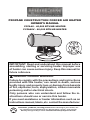
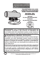
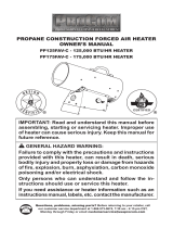
PROPANE CONSTRUCTION FORCED AIR HEATER
OWNER’S MANUAL
PCFA40 - 40,000 BTU/HR HEATER
PCFA60V - 60,000 BTU/HR HEATER
IMPORTANT: Read and understand this manual before
assembling, starting or servicing heater. Improper use
of heater can cause serious injury. Keep this manual for
future reference.
GENERAL HAZARD WARNING:
Failure to comply with the precautions and instructions
provided with this heater, can result in death, serious
bodily injury and property loss or damage from hazards
of re, explosion, burn, asphyxiation, carbon monoxide
poisoning and/or electrical shock.
Only persons who can understand and follow the in-
structions should use or service this heater.
If you need assistance or heater information such as an
instructions manual, labels, etc. contact the manufacturer.
Questions, problems, missing parts? Before returning to your retailer, call
our customer service department at 1-866-573-0674, 7:30 am - 4:15 pm CST,
Monday through Friday or email customerservice@usaprocom.com

www.usaprocom.com
160448-01C2
SPECIFICATIONS
Model PCFA40 PCFA60V
Output Rating 40,000 BTU/Hr 60,000 BTU/Hr
Fuel Consumption/Hour 0.44 gal (1.65 liter),
1.86 lb (0.84 kg)
0.66 gal (2.48 liter),
2.78 lb (1.26 kg)
Manifold Pressure 9.7 PSI 19.8 PSI
Ignition Manual Piezo Electric Spark
Fuel Propane Vapor
Supply Pressure To Regulator Minimum* 20 psi Minimum* 25 psi
Maximum Tank Pressure or 200 psi
Regulator Outlet Pressure 10 PSI 20 PSI
Motor 2000 RPM 2900 RPM
Electric Input 120 Volt/60 Hertz/1 Phase
Amperage 0.6
Temperature Range for Heater Operation 0° F to 85° F** (-17° C to 29.4° C**)
* For purposes of input adjustment
** When running heater in temperatures above 85° F (29.44° C), high internal temperatures may cause
thermal limit device to shut down heater.
TABLE OF CONTENTS
Specications ............................................ 2
Safety ........................................................ 3
Unpacking.................................................. 4
Product Identication ................................. 4
Theory of Operation................................... 5
Propane Supply ......................................... 5
Installation ................................................. 5
Ventilation .................................................. 7
Operation ................................................... 7
Storage ...................................................... 8
Maintenance .............................................. 8
Service Procedures ................................... 9
Troubleshooting ........................................11
Parts ........................................................ 12
Wiring Diagram ........................................ 16
Replacement Parts .................................. 16
Accessories ............................................. 17
Technical Services ................................... 17
Warranty .................................................. 18

www.usaprocom.com
3160448-01C
SAFETY
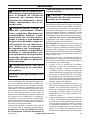
ziness and/or nausea. If you have these signs,
the heater may not be working properly. Get
fresh air at once! Check for proper ventilation
and have heater serviced.
Propane Gas: Propane gas is odorless. An
odor-making agent is added to propane gas.
The odor helps you detect a propane gas
leak. However, the odor added to propane
gas can fade. Propane gas may be present
even though no odor exists.
Make certain you read and understand all
warnings. Keep this manual for reference. It
is your guide to safe and proper operation of
this heater.
1. Install and use heater with care. Follow
all local ordinances and codes. In the ab-
sence of local ordinances and codes, refer
to the Standard for Storage and Handling
of Liqueed Petroleum Gas, ANSI/NFPA
58 and the Natural and Propane Gas
Installation Code, CAN/CGA B149.1. This
instructs on the safe storage and handling
of propane gases.
2. Use only the electrical voltage and fre-
quency specied on model plate. The
electrical connections and grounding of
the heater shall follow the National Electric
Code, ANSI/NFPA 70 or the Canadian
Electrical Code, Part 1.
3. Electrical grounding instructions - This
appliance is equipped with a three-prong
(grounding) plug for your protection against
shock hazard and should be plugged di-
rectly into a properly grounded three-prong
receptacle or extension cord.
4. This product has been approved for use
in the Commonwealth of Massachusetts.
5. Use only a three-prong, grounded exten-
sion cord.
6. Use only the hose and factory preset
regulator provided with the heater.
7. Use only propane gas set up for vapor
withdrawal.
8. Provide adequate ventilation. Before
using heater, provide at least a 1.5 ft
2
(1400 cm
2
) opening of fresh, outside air.
9. For either indoor or outdoor use. Adequate
ventilation must be provided. Do not use
heater outdoors.
10. Do not use heater in occupied dwellings
or in living or sleeping quarters.
WARNING: This product
contains and/or generates
chemicals known to the State
of California to cause cancer or
birth defects or other reproduc-
tive harm.
WARNING: Fire, burn, in-
halation and explosion hazard.
Keep solid combustibles, such
as building materials, paper or
cardboard, a safe distance away
from the heater as recommended
by the instructions. Never use
the heater in spaces which do or
may contain volatile or airborne
combustibles or products such
as gasoline, solvents, paint thin-
ner, dust particles or unknown
chemicals.
WARNING: Not for home or
recreational vehicle use.
For use with Propane/LP gas only.
The heater is designed for use as a con-
struction heater in accordance with ANSI
Z83.7•CGA2.14. Other standards govern
the use of fuel gases and heating products
for specic uses. Your local authority can
advise you about these. The primary purpose
of construction heaters is to provide tempo-
rary heating of buildings under construction,
alteration or repair. Properly used, the heater
provides safe economical heating. Products
of combustion are vented into the area being
heated.
We cannot foresee every use which may be
made of our heaters. Check with your local
re safety authority if you have questions
about heater use.
DANGER: Carbon monoxide
poisoning may lead to death!
Carbon Monoxide Poisoning: Some people
are more affected by carbon monoxide than
others. Early signs of carbon monoxide poi-
soning resemble the flu, with headaches, diz-

www.usaprocom.com
160448-01C4
SAFETY
11. Do not use heater in basement or below
ground level. Propane gas is heavier than
air. If a leak occurs, propane gas will sink
to the lowest possible level.
12. Keep appliance area clear and free from
combustible materials, gasoline, paint
thinner and other flammable vapors and
liquids.
13. Do not use heater in areas with high dust
content. Dust is combustible.
14. Minimum heater clearances from com-
bustibles:
Outlet: 8 Ft. (2.44 m)
Sides: 2 Ft. (0.61 m), Top: 6 Ft. (1.83 m)
Rear: 2 Ft. (0.61 m)
Locate 10 ft. (3 m) from canvas or plastic
tarpaulins or similar coverings and secure
them to prevent flapping or movement due
to wind action.
15. Keep heater at least 6 feet (1.83 m) from
propane tank(s) in USA or 10 feet (3 m)
from propane tank(s) in Canada. Do not
point heater at a propane/LP tank within
20 feet (6.1 m).
16. Keep propane tank(s) below 100° F
(37.8° C).
17. Check heater for damage before each
use. Do not use a damaged heater.
18. Check hose before each use of heater.
If highly worn or cut, replace with hose
specied by manufacturer before using
heater.
19. Locate heater on a stable and level surface.
Do not move while heater is hot or running.
Position heater properly before use.
20. Not intended for use on nished floors.
21. Never block air inlet (rear) or air outlet
(front) of heater.
22. Do not leave heater unattended.
23.
Keep children and animals away from heater.
24. Never move, handle or service a hot, op-
erating or plugged-in heater. Severe burns
may result. You must wait 15 minutes after
turning heater off.
25. To prevent injury, wear gloves when han-
dling heater.
26. Never attach duct work to front or rear of
heater.
27. Do not alter heater. Keep heater in its
original state.
28. Do not use heater if altered.
29. Turn off propane supply and unplug heater
when not in use.
30. Use only original replacement parts. This
heater must use design-specic parts.
Do not substitute or use generic parts.
Improper replacement parts could cause
serious or fatal injuries.
UNPACKING
1. Remove all packing items applied to
heater for shipment. Keep plastic cover
caps (attached to inlet connector and
hose/regulator assembly) for storage.
2. Remove all items from carton.
3. Check all items for shipping damage. If
heater is damaged, call our customer
service department at 1-866-573-0674.
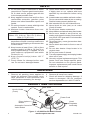
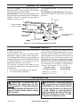
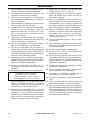
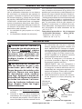
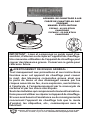
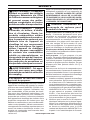
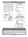
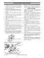
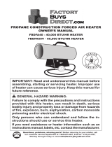
PRODUCT IDENTIFICATION
Hot Air Outlet
(Front)
Outer Shell
Motor
Power Cord
Piezo Ignitor
Button
Automatic Control
Valve Button
Hose/
Regulator
Assembly
Handle
Figure 1 - 40,000 Btu/Hr Model Shown

www.usaprocom.com
5160448-01C
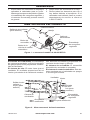
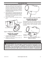
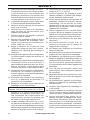
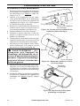
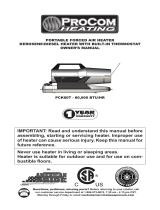
INSTALLATION
Figure 2 - Cross Section Operational View
Air For Combustion
Air For Heating
Clean Heated
Air Out (Front)
Fan
Motor
Cool
Air In
(Back)
Combustion
Chamber
Hose/Regulator
Assembly
THEORY OF OPERATION
The Fuel System: The hose/regulator as-
sembly attaches to the propane gas supply.
This provides fuel to the heater.
The Air System: The motor turns the fan. The
fan pushes air into and around the combustion
chamber. This air is heated and provides a
stream of clean, hot air.
The Ignition System: The piezo ignitor lights
the burner.
The Automatic Control System: This system
causes the heater to shut down if the flame
goes out.
PROPANE SUPPLY
Propane gas and propane tank(s) are to be
furnished by the user.
Use this heater only with a propane vapor
withdrawal supply system. See Chapter 5
of the Standard for Storage and Handling of
Liqueed Petroleum Gas, ANSI/NFPA 58 and/
or CAN/CGA B149.2. Your local library or re
department will have this booklet.
The amount of propane gas ready for use
from propane tanks varies. Two factors decide
this amount:
1. The amount of propane gas in tank(s)
2. The temperature of tank(s)
This heater is designed to operate with a
minimum 20 lb (9 kg) propane tank. You may
need two or more tanks or one larger tank in
colder weather. It is recommended you use a
100 lb (45 kg) tank for longer operation. See
chart below. Less gas is vaporized at lower
temperatures. Your local propane gas dealer
will help you select the proper supply system.
The minimum surrounding air temperature
rating for each heater is 0° F (-18° C).
Average Temp No. Of Tanks
At Tank Location 100 lb (45 kg)
Above 0° F (-18° C) 1
Below 0° F (-18° C) 2
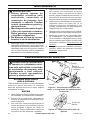
WARNING: Review and un-
derstand the warnings in the
Safety, page 3. They are needed
to safely operate this heater. Fol-
low all local codes when using
this heater.
WARNING: Test all gas piping
and connections for leaks after
installation or servicing. Never
use an open ame to check for
a leak. Apply a noncorrosive
leak detection uid to all joints.
Bubbles forming show a leak.
Correct all leaks at once.

www.usaprocom.com
160448-01C6
1. Provide propane supply system (see
Propane Supply, page 5).
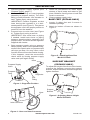
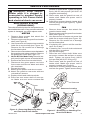
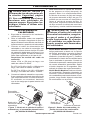
2. Connect POL tting on hose/regulator
assembly to propane tank(s). Turn POL
tting counterclockwise into threads on
tank. Tighten rmly using wrench.
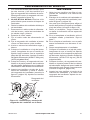
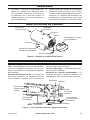
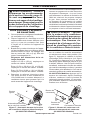
IMPORTANT: Position regulator so that
hose leaving the regulator is in a hori-
zontal position (see Figure 3). This places
the regulator vent in the proper position to
protect it from the weather.
3. Connect hose to valve inlet (see Figure
4). Tighten rmly using a wrench.
IMPORTANT: Use extra hose or piping
if needed. Install extra hose or piping
between hose/regulator assembly and
propane tank. You must use the regulator
supplied with heater.
4. Open propane supply valve on propane
tank(s) slowly. Note: If not opened slowly,
excess-ow check valve on propane tank
will stop gas ow. You may hear a click
from the excess-ow check valve closing.
If this happens, reset the excess-ow
check valve by closing propane supply
valve and open again slowly.
Figure 4 - Hose and Inlet Connector
Hose
Inlet Connector
INSTALLATION
Figure 3 - Regulator Position
Figure 5 - Attaching Base Feet
Model PCFA40
Figure 6 - Adjusting Heater Height
Model PCFA60V
Propane
Tank
Propane Supply
Valve
Regulator
Support
Bracket
Fastener
Hose
POL
Fitting
5. Check all connections for leaks. Apply
mixture of liquid soap and water to gas
joints. Bubbles forming show a leak that
must be corrected.
6. Close propane supply valve.
BASE FEET (PCFA40 ONLY)
1. Locate 2 rubber feet and 2 screws in
hardware package.
2. Attach to bottom of base as shown in
Figure 5.
SUPPORT BRACKET
(PCFA60V ONLY)
To adjust the height of the front of the heater,
unscrew the fastener securing the support
bracket. Adjust bracket to desired height and
tighten fastener.

www.usaprocom.com
7160448-01C
VENTILATION
WARNING: Provide at least a 1.5 ft
2
(0.46 m
2
) opening of fresh,
outside air while running heater. If proper fresh, outside air ventila-
tion is not provided, carbon monoxide poisoning can occur. Provide
proper fresh, outside air ventilation before running heater.
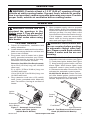
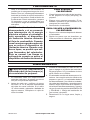
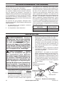
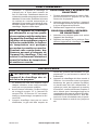
OPERATION
Inlet Connector
Figure 7 - Automatic Control Valve
Button and Piezo Ignitor
(40,000 Btu/Hr Models)
Figure 8 - Fuel Button and Fuel Control
Knob (60,000 Btu/Hr Models)
Ignitor
Button
Automatic Control
Valve Button
Fuel Button
Control
Knob
WARNING: Review and un-
derstand the warnings in the
Safety, page 3. They are needed
to safely operate this heater. Fol-
low all local codes when using
this heater.
TO START HEATER
1. Follow all installation, ventilation and
safety information.
2. Locate heater on stable and level surface.
Make sure strong drafts do not blow into
front or rear of heater.
3. Plug power cord of heater into a three-
prong, grounded extension cord. Exten-
sion cord must be at least 6 feet long.
Extension cord must be UL listed.
Extension Cord Wire Size Requirements
Up to 50 ft (15.24 m) long, use 18 AWG
rated cord.
51 to 100 ft (15.54 to 30.48 m) long, use
16 AWG rated cord.
101 to 200 ft (30.78 to 60.96 m) long, use
14 AWG rated cord.
4. Plug extension cord into a 120 volt/60
hertz, 3-hole, grounded outlet. Motor will
start. Fan will turn, forcing air out front of
heater.
5. Open propane supply valve on propane
tank(s) slowly. Note: If not opened slowly,
excess-ow check valve on propane tank
will stop gas ow. You may hear a click
from the excess-ow check valve closing.
If this happens, reset the excess-ow
check valve by closing propane supply
valve and open again slowly.
WARNING: Be sure motor and
fan are running before pushing
in automatic control valve but-
ton. Flames could ash outside
heater if motor and fan are not
running.
6. 40,000 Btu/Hr Models Push in and hold
automatic control valve button (see Figure
7). Push piezo ignitor button (see Figure
7). Keep pushing ignitor button until the
burner lights. When burner lights, keep
automatic control valve button pushed
in. Release button after 30 seconds. This
activates the automatic control system.
60,000 Btu/Hr Models Press fuel but-
ton. After heater ignites, continue to hold
fuel button pressed for 15 seconds, then
release. Adjust burn rate with knob.

www.usaprocom.com
160448-01C8
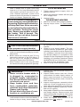
MAINTENANCE
WARNINGS
• Never service heater while it
is plugged in, connected to
propane supply, operating or
hot. Severe burns and electri-
cal shock can occur.
• Keep heater clear and free
from combustible materials,
gasoline and other ammable
vapors and liquids.
• Do not block the ow of com-
bustion or ventilation air.
1. Keep heater clean. Clean heater annually
or as needed to remove dust and debris. If
heater is dirty or dusty, clean heater with
a damp cloth. Use household cleaners on
difcult spots.
2. Inspect heater before each use. Check
connections for leaks. Apply mixture of
liquid soap and water to connections.
Bubbles forming show a leak. Correct all
leaks at once.
3.
Inspect hose/regulator assembly before
each use. If hose is highly worn or cut, re-
place with hose specied by manufacturer.
4. Have heater inspected yearly by a quali-
ed service agency.
5. Keep inside of heater free from combustible
and foreign objects. Remove motor and
other internal parts if needed to clean inside
of heater (see Service Procedures, page 9).
6. Clean fan blades each season or as
needed (see Fan, page 9).
STORAGE
CAUTION: Disconnect heater
from propane supply tank(s).
1. The heater should be inspected before
each use and at least annually by a quali-
ed person.
2. Before each use, check the soft "O" ring
seat at the bullnose of the POL tting. If
the "O" ring is cut, scuffed or otherwise
damaged, replace the POL tting.
3. When heater is not in use, the gas shall
be turned off at the propane/LP gas sup-
ply cylinder(s) by closing the valve on the
cylinder.
4. Heater is to be stored indoors. The con-
nection between propane/LP gas supply
cylinder(s) and heater must be disconnect-
ed, cylinder(s) removed from the heater
and stored outdoors in accordance with
Chapter 5 of the Standard for Storage and
Handling of Liqueed Petroleum Gases
ANSI/NFPA 58 and CSA B149.1, Natural
Gas and Propane Installation Code.
5. Store in a dry, clean and safe place.
OPERATION
Note: If heater fails to ignite, hose may
have air in it. If so, keep automatic control
valve button pressed and wait 20 sec-
onds. Release automatic control valve
button and wait 20 seconds for unburned
fuel to exit heater. Repeat this step.
NOTICE: If heater is unplugged or
power outage occurs while heater
is running, the thermal limit device
will stop fuel ow. A few seconds
occur before the thermal limit de-
vice activates. During this short
time, ames may appear outside
the heater. This is normal. The
ames will go out when thermal
limit device activates.
TO STOP HEATER
1. Tightly close propane supply valve on
propane tank(s).
2. Wait a few seconds. Heater will burn gas
left in supply hose.
3. Unplug heater.
TO RESTART HEATER
1. Wait ve minutes after stopping heater.
2. Repeat steps under To Start Heater,
page 7.

www.usaprocom.com
9160448-01C
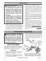
Figure 9 - Removing/Replacing Motor
and Fan Guard from Heater
Figure 10 - Setscrew Location
Setscrew
SERVICE PROCEDURES
WARNING: Never service
heater while it is plugged in,
connected to propane supply,
operating or hot. Severe burns
and electrical shock can occur.
ELECTRICAL SYSTEM
(PCFA40 ONLY)
The entire electrical system for this heater is con-
tained within the motor. If any part of the electrical
system is damaged, you must replace motor.
MOTOR
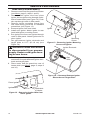
1. Remove three screws that attach fan
guard to heater shell.
2. Remove motor and fan guard from heater
shell (see Figure 9).
3. Use hex wrench to loosen set screw which
holds fan to motor shaft (see Figure 10).
Remove fan. Be careful not to damage
the fan blade pitch.
4.
Remove two nuts and two screws that attach
fan guard to motor using nut-driver. Remove
fan guard from motor (see Figure 11).
5. 60,000 BTU/Hr Model Only Remove bot-
tom panel to gain access to terminal block.
6. Remove fan wires from terminal block.
7. Disconnect the green power cord wire
from motor and remove black and white
wire terminals.
8. Discard old motor.
9. Attach green power cord wire to motor.
10. Attach fan guard to new motor with two
nuts and two screws.
11. Replace black and white terminals.
12. Place fan onto motor shaft of new mo-
tor. Make sure set screw contacts flat
Screw
Screw
Motor and
Fan Guard
Figure 11 - Removing or Attaching Fan
Guard from Motor
Fan
Guard
Motor
Screw
surface on motor shaft. Tighten set screw
rmly (40-50 inch-pounds [46.08-57.60
kilogram-centimeters]).
13. Place motor and fan guard into rear of
heater shell. Make sure power cord is
properly located.
14. Insert three screws through heater shell
and into fan guard (see Figure 9). Tighten
screws rmly.
FAN
1. Remove three screws that attach fan
guard to heater shell.
2. Remove motor and fan guard from heater
shell (see Figure 9).
3. Use hex wrench to loosen set screw that
holds fan to motor shaft (see Figure 10).
4. Remove fan. Be careful not to damage
the fan blade pitch.
5a. If replacing fan, remove old fan and dis-
card. Go to step 7.
5b. If cleaning fan, use soft cloth moistened
with kerosene or solvent.
6. Dry fan thoroughly.
7. Place fan onto motor shaft. Make sure
set screw contacts flat surface on motor
shaft. Tighten set screw firmly (40-50
inch-pounds [46.08-57.60 kg-cm]).
8. Place motor and fan guard into rear of
heater shell. Make sure power cord is
properly located (see Figure 9).
9. Insert three screws through heater shell
and into fan guard. Tighten screws rmly.

www.usaprocom.com
160448-01C10
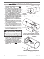
Figure 13 - Removing Ignitor Mounting
Screw and Ignitor
Ignitor
Mounting
Screw
Figure 14 - Clearance Between Ignitor
Electrode and Target Plate
Ignitor Electrode
Gap
Area
SERVICE PROCEDURES
IGNITOR (PCFA40 ONLY)
1. Remove motor and fan guard from heater
(see Motor, page 9, steps 1 and 2).
2. Remove black ignitor wire from piezo
ignitor. Access ignitor wire through under-
side of heater base (see Figure 12). Push
wire up through notch in ller panel.
3. Remove ignitor mounting screw from
rear head using nut-driver or standard
screwdriver (see Figure 13).
4. Remove ignitor from rear head.
5. Install new ignitor. Attach ignitor to rear
head with ignitor mounting screw.
6. Run ignitor wire from new ignitor through
notch in ller panel. Attach ignitor wire to
piezo ignitor.
7. Set gap between ignitor electrode and
target plate to 0.17" (43.18 cm) (see
Figure 14).
WARNING: Make sure heater
is disconnected from propane
supply. Heater could ignite caus-
ing severe burns.
8. Test for spark. Push piezo ignitor button
and watch for spark between ignitor elec-
trode and target plate.
9. Place motor and fan guard into rear of
heater shell (see Motor, page 9, steps 9
and 10).
Figure 12 - Removing Ignitor Wire from
Piezo Ignitor
Ignitor Wire
Piezo Ignitor
Underside
of Heater

www.usaprocom.com
11160448-01C
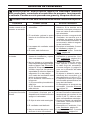
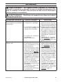
TROUBLESHOOTING
WARNING: Never service heater while it is plugged in, connected
to propane supply, operating or hot. Severe burns and electrical
shock can occur.
WARNING: Use only in areas free of high dust content.
Problem Possible Cause Corrective Action
Fan does not turn when
heater is plugged in.
1. No electrical power to heater.
2. Fan hitting inside of heater
shell.
3. Fan blades bent.
4. Defective motor.
1. Check voltage to electrical
outlet. If voltage is good,
check heater power cord for
breaks.
2. Adjust motor/fan guard to
keep fan from hitting inside
of heater shell. Bend fan
guard if necessary.
3. Replace fan. See Fan, page
9.
4. Replace motor. See Motor,
page 9.
Heater will not ignite. 1. User did not follow installa-
tion or operation instructions
properly.
2. No spark at ignitor. To test
for spark, follow step 8 under
Ignitor, page 10. If you see
spark at ignitor, have heater
serviced by qualied service
person. If no spark seen:
A) Loose or disconnected
ignitor wire
B) Wrong spark gap
C) Piezo ignitor loose
D) Bad ignitor electrode
1. Repeat installation and op-
eration instructions. See
Installation, page 5 and
Operation, page 7.
2. A) Check ignitor wire. Tight-
en or reattach loose ignitor
wire. See Figure 11, page 8
for ignitor wire location
B) Set gap between ignitor
electrode and target plate to
0.17" (0.43 cm)
C) Tighten nut holding piezo
ignitor to base of heater
D) Replace ignitor electrode.
See Ignitor, page 10
Heater shuts down while
running.
1. High surrounding air tem-
perature causing thermal
limit device to shut down
heater.
2. Restricted air flow.
3. Damaged fan.
4. Excessive dust or debris in
surrounding area.
1. This can happen when run-
ning heater in temperatures
above 85° F (29.44° C). Run
heater in cooler tempera-
tures.
2 Check heater inlet and out-
let. Remove any obstruc-
tions.
3. Replace fan. See Fan, page 9.
4. Clean heater. See Mainte-
nance, page 8.

www.usaprocom.com
160448-01C12
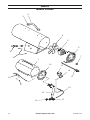
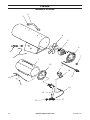
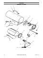
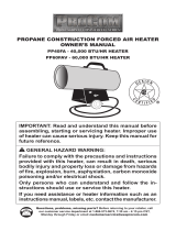
PARTS
MODEL PCFA40
2
12
13
14
15
16
17
18
4
6
5
8
7
1
3
10
11
9
19

www.usaprocom.com
13160448-01C
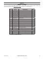
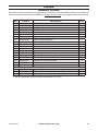
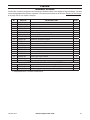
PARTS
MODEL PCFA40
This list contains replaceable parts used in your heater. When ordering parts, follow the
instructions listed under Replacement Parts on page 17 of this manual.
Item Part # Description Qty
1 ** Combustion Chamber 1
2 160334-01 Handle 1
3 160335-01BK Handle Bracket 2
4 160321-01 Fan 1
5 160317-02 Motor 1
6 160319-01BK Motor Mounting Bracket 1
7 PF06-1201-D Strain Relief Bushing 1
8 160318-02 Power Cord 1
9 160323-01 Piezo Ignitor 1
10 160325-01 Electrode Ignitor 1
11 160278-01 Screw 1
12 ** Rear Head 1
13 160440-01 Thermostat Switch 1
14 160331-01 Wire Assembly 1
15 160449-01 Thermocouple 1
16 160327-01 Burner Assembly 1
17 160326-01 Main Orice Valve 1
18 160265-01 Palnut Fastener 1
19 160331-05 Ignitor Wire 1
PARTS AVAILABLE - NOT SHOWN
160451-01 Operation/Model Data Decal 1
160452-01 Operation Decal (Spanish/French) 1
160332-01 Hose/Regulator Assembly 1
** Not a eld replaceable part.

www.usaprocom.com
160448-01C14
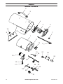
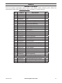
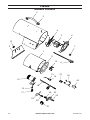
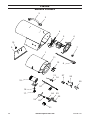
PARTS
MODEL PCFA60V
8
7
2
3
4
5
10
9
6
1
11
12
15
16
17
18
21
22
23
24
19
13
14
27
26
25
20

www.usaprocom.com
15160448-01C
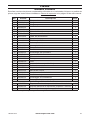
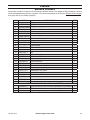
Item Part # Description Qty
1 ** Combustion Chamber 1
2 160334-01 Handle 1
3 160335-01BK Handle Bracket 2
4 160456-01 Fan 1
5 160317-01 Motor 1
6 160463-01BK Motor Mounting Bracket 1
7 PF06-1201-C Strain Relief Bushing 1
8 160318-01 Power Cord 1
9 ** Support Bracket 1
10 ** Fastener Screw 1
11 ** Rear Head 1
12 160440-02 Thermostat Switch 1
13 160481-01 Electrode Ignitor 1
14 160278-01 Screw 1
15 160482-01 Burner Assembly 1
16 160474-01 Injector, 0.034 1
17 160508-01 Female Elbow 1
18 160449-02 Thermocouple 1
19 160480-02 Tube 1
20 160478-01 Female Compression Fitting 1
21 160304-03 Control Knob 1
22 160477-01 Brass Adaptor 1
23 160476-01 Control Valve 1
24 160294-06 Ball Valve Assembly 1
25 160479-01 Relay Assembly 1
26 160485-01 Ignitor Assembly 1
27 160483-01 Terminal Block 1
PARTS AVAILABLE - NOT SHOWN
160492-01 Operation/Model Data Decal 1
160491-01 Operation Decal (Spanish/French) 1
160468-01 Hose/Regulator Assembly 1
** Not a eld replaceable part.
PARTS
MODEL PCFA60V
This list contains replaceable parts used in your heater. When ordering parts, follow the
instructions listed under Replacement Parts on page 17 of this manual.

www.usaprocom.com
160448-01C16
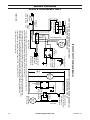
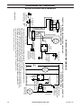
WIRING DIAGRAM
60,000 BTU/HR MODEL ONLY
160518-01A
Black** or Orange**/
Negro** o Naranja**/
Noir** ou orange**
L1
L2
White/Blanco/
Blanc
Blue*/Azul*/Bleu*
Blue*/Azul*/Bleu*
Blue/Azul/Bleu
White/Blanco/
Blanc
White/Blanco/Blanc
Black/
Negro/Noir
Black/Negro/Noir
Black/Negro/Noir
Black/Negro/Noir
Green/
Verde/
Vert
Orange/
Naranja
Orange/
Naranja
Orange/
Naranja
Orange/
Naranja
Thermocouple/Termopar
CONNECTION DIAGRAM/DIAGRAMA DE CONEXIONES/
DIAGRAMME DE CONNEXION
SCHEMATIC DIAGRAM/DIAGRAMA ESQUEMÁTICO/
DIAGRAMME DE CIRCUIT
60,000/125,000/175,000 Models/Modelos
Relay/Relé/Relais
Motor/
Moteur
Ignitor/
Encendedor/
Allumeur
High-Limit Switch/
Interruptor de
límite alto/
Commutateur de
limite supérieure
• If any original wiring as supplied with the heater must be replaced, it must be replaced with type AWG 105° C
wire or its equivalent except as indicated (*Type SF2-200. **UL Style 3257 250° C)
• Si es necesario reemplazar algún cable suministrado originalmente con el calentador, éste se debe reemplazar con
cable tipo AWG 105° C o su equivalente, excepto cuando se indica lo contrario (*Tipo SF2-200. **UL Style 3257 250° C)
* Si le câblage fourni avec l'appareil de chauffage doit être remplacé, faites-le avec du câble de type AWG 105° C
ou son équivalent, sauf indication contraire (*Type SF2-200. **UL Style 3257 250° C)
Line Cord/
Cable de línea/
Cordon électrique
Motor/
Moteur
High Limit Switch/
Interruptor de límite alto/
Interrupteur de
limite supérieure
White/Blanco/Blanc
Black/Negro/Noir
115V
60HZ
Gas
Valve
Relay/
Relé/
Relais
Thermocouple/
Termopar
Green/Verde/Vert
L1
L2
Ignitor/
Encendedor/
Allumeur
Válvula de gas/
Robinet de gaz
Electrode/Electrodo/
Électrode
Electrode/Electrodo/
Électrode
• Label all wires prior to disconnecting.

www.usaprocom.com
17160448-01C
REPLACEMENT PARTS
Note: Use only original replacement parts. This will protect your warranty coverage for parts
replaced under warranty.
PARTS NOT UNDER WARRANTY
Contact authorized dealers of this product.
If they can’t supply original replacement
part(s) call Customer Service toll free at
1-866-573-0674 for referral information.
When calling Customer Service have ready:
• Model number of your heater
• The replacement part number
PARTS UNDER WARRANTY
Contact authorized dealers of this product.
If they can’t supply original replacement
parts, call Customer Service toll free at
1-866-573-0674 for referral information.
When calling Customer Service or your
dealer, have ready:
• Your name
• Your address
• Model and serial number of your heater
• How heater was malfunctioning
• Type of gas supply and Propane/LP tank
size
• Purchase date
Usually, we will ask you to return the defective
part to the factory
ACCESSORIES
Purchase these accessories from your local dealer. If they can not supply these accessories,
call ProCom Heating, Inc. at 1-866-573-0674 for information.
TECHNICAL SERVICES
You may have further questions about installation, operation, or troubleshooting. If so, contact
ProCom Heating, Inc. at 1-866-573-0674. When calling please have your model and serial
numbers of your heater ready.
You can also visit ProCom Heating, Inc.’s web site at www.usaprocom.com.

www.usaprocom.com
160448-01C18
NOTES
________________________________________________________________________
________________________________________________________________________
________________________________________________________________________
________________________________________________________________________
________________________________________________________________________
________________________________________________________________________
________________________________________________________________________
________________________________________________________________________
________________________________________________________________________
________________________________________________________________________
________________________________________________________________________
________________________________________________________________________
________________________________________________________________________
________________________________________________________________________
________________________________________________________________________
________________________________________________________________________
________________________________________________________________________
________________________________________________________________________
________________________________________________________________________
________________________________________________________________________
________________________________________________________________________
________________________________________________________________________
________________________________________________________________________
________________________________________________________________________
________________________________________________________________________
________________________________________________________________________
________________________________________________________________________
________________________________________________________________________
________________________________________________________________________
________________________________________________________________________
________________________________________________________________________
________________________________________________________________________
________________________________________________________________________

www.usaprocom.com
19160448-01C
NOTES
________________________________________________________________________
________________________________________________________________________
________________________________________________________________________
________________________________________________________________________
________________________________________________________________________
________________________________________________________________________
________________________________________________________________________
________________________________________________________________________
________________________________________________________________________
________________________________________________________________________
________________________________________________________________________
________________________________________________________________________
________________________________________________________________________
________________________________________________________________________
________________________________________________________________________
________________________________________________________________________
________________________________________________________________________
________________________________________________________________________
________________________________________________________________________
________________________________________________________________________
________________________________________________________________________
________________________________________________________________________
________________________________________________________________________
________________________________________________________________________
________________________________________________________________________
________________________________________________________________________
________________________________________________________________________
________________________________________________________________________
________________________________________________________________________
________________________________________________________________________
________________________________________________________________________
________________________________________________________________________
________________________________________________________________________

160448-01
Rev. C
07/15
REGISTER YOUR PRODUCT AT WWW.USAPROCOM.COM
PROCOM HEATING, INC. LIMITED WARRANTIES
New Products – Outdoor Heating
Standard Warranty: ProCom Heating, Inc. warrants this new product and any parts thereof to be free from
defects in material and workmanship for a period of one (1) year from the date of rst purchase from an
authorized dealer provided the product has been installed, maintained and operated in accordance with
ProCom Heating, Inc.’s warnings and Instructions.
For products purchased for commercial, industrial or rental usage, this warranty is limited to 90 days from
the date of rst purchase.
Factory Reconditioned Products
Limited Warranty: ProCom Heating, Inc. warrants factory reconditioned products and any parts thereof to
be free from defects in material and workmanship for a period 30 days from the date of rst purchase from an
authorized dealer provided the product has been installed, maintained and operated in accordance with ProCom
Heating, Inc.’s warnings and Instructions. No return will be authorized. Parts will be provided to repair the product.
Terms Common to All Warranties
The following terms apply to all of the above warranties:
Always specify model number and serial number when contacting the manufacturer. To make a claim under
this warranty, the bill of sale or other proof of purchase must be presented.
This warranty is extended only to the original retail purchaser when purchased from an authorized dealer,
and only when installed by a qualied installer in accordance with all local codes and instructions furnished
with this product.
This warranty covers the cost of part(s) required to restore this product to proper operating condition and
an allowance for labor when provided by a ProCom Heating, Inc. Authorized Service Center or a provider
approved by ProCom Heating, Inc. Warranty parts must be obtained through authorized dealers of this
product and/or ProCom Heating, Inc. who will provide original factory replacement parts. Failure to use
original factory replacement parts will void this warranty.
Traveling, handling, transportation, diagnostic, material, labor and incidental costs associated with warranty
repairs, unless expressly covered by this warranty, are not reimbursable under this warranty and are the
responsibility of the owner.
Excluded from this warranty are products or parts that fail or become damaged due to misuse, accidents,
improper installation, lack of proper maintenance, tampering or alteration(s).
This is ProCom Heating, Inc.’s exclusive warranty, and to the full extent allowed by law; this express war-
ranty excludes any and all other warranties, express or implied, written or verbal and limits the duration of
any and all implied warranties, including warranties of merchantability and tness for a particular purpose to
one (1) year on new products and 30 days on factory reconditioned products from the date of rst purchase.
ProCom Heating, Inc. makes no other warranties regarding this product.
ProCom Heating, Inc.’s liability is limited to the purchase price of the product and ProCom Heating, Inc.
shall not be liable for any other damages whatsoever under any circumstances including direct, indirect,
incidental, or consequential damages.
Some States do not allow limitations on how long an implied warranty lasts or the exclusion or limitation of
incidental or consequential damages, so the above limitation or exclusion may not apply to you.
This warranty gives you specic legal rights, and you may also have other rights which vary from state to state.
WARRANTY
KEEP THIS WARRANTY
Model (
located on product or identication tag
) _____________________________
Serial No. (
located on product or identication tag
) __________________________
Date Purchased ______________________________________
Keep receipt for warranty verication.
ProCom Heating, Inc.
Bowling Green, KY 42101
www.usaprocom.com
1-866-573-0674
La page est en cours de chargement...
La page est en cours de chargement...
La page est en cours de chargement...
La page est en cours de chargement...
La page est en cours de chargement...
La page est en cours de chargement...
La page est en cours de chargement...
La page est en cours de chargement...
La page est en cours de chargement...
La page est en cours de chargement...
La page est en cours de chargement...
La page est en cours de chargement...
La page est en cours de chargement...
La page est en cours de chargement...
La page est en cours de chargement...
La page est en cours de chargement...
La page est en cours de chargement...
La page est en cours de chargement...
La page est en cours de chargement...
La page est en cours de chargement...
La page est en cours de chargement...
La page est en cours de chargement...
La page est en cours de chargement...
La page est en cours de chargement...
La page est en cours de chargement...
La page est en cours de chargement...
La page est en cours de chargement...
La page est en cours de chargement...
La page est en cours de chargement...
La page est en cours de chargement...
La page est en cours de chargement...
La page est en cours de chargement...
La page est en cours de chargement...
La page est en cours de chargement...
La page est en cours de chargement...
La page est en cours de chargement...
La page est en cours de chargement...
La page est en cours de chargement...
La page est en cours de chargement...
La page est en cours de chargement...
-
 1
1
-
 2
2
-
 3
3
-
 4
4
-
 5
5
-
 6
6
-
 7
7
-
 8
8
-
 9
9
-
 10
10
-
 11
11
-
 12
12
-
 13
13
-
 14
14
-
 15
15
-
 16
16
-
 17
17
-
 18
18
-
 19
19
-
 20
20
-
 21
21
-
 22
22
-
 23
23
-
 24
24
-
 25
25
-
 26
26
-
 27
27
-
 28
28
-
 29
29
-
 30
30
-
 31
31
-
 32
32
-
 33
33
-
 34
34
-
 35
35
-
 36
36
-
 37
37
-
 38
38
-
 39
39
-
 40
40
-
 41
41
-
 42
42
-
 43
43
-
 44
44
-
 45
45
-
 46
46
-
 47
47
-
 48
48
-
 49
49
-
 50
50
-
 51
51
-
 52
52
-
 53
53
-
 54
54
-
 55
55
-
 56
56
-
 57
57
-
 58
58
-
 59
59
-
 60
60


Procom PCFA40 Mode d'emploi
- Catégorie
- Congélateurs
- Taper
- Mode d'emploi
dans d''autres langues
- English: Procom PCFA40 User guide
- español: Procom PCFA40 Guía del usuario
Documents connexes
Autres documents
-
 ProCom Heating PCFA60V-C Manuel utilisateur
-
Desa RCLP50-F Manuel utilisateur
-
-
 ProCom Heating PP125FAV Manuel utilisateur
-
 ProCom Heating 200023 Manuel utilisateur
-
 ProCom Heating PP125FAV-C Manuel utilisateur
-
 Avenger FBDFA60V Manuel utilisateur
-
 ProCom Heating PCK80T Manuel utilisateur
-
 ProCom Heating PP40FA Manuel utilisateur
-
ProCom Heating PP40FA-C Manuel utilisateur


