Miller Coolmate 3.5 Le manuel du propriétaire
- Catégorie
- Système de soudage
- Taper
- Le manuel du propriétaire
Ce manuel convient également à

Coolmatet3.5
Processes
Description
TIG (GTAW) Welding
OM-231 313P 2015−02
File: TIG (GTAW)
MIG (GMAW) Welding
Visit our website at
www.MillerWelds.com
CE and Non-CE

Miller Electric manufactures a full line
of welders and welding related equipment.
For information on other quality Miller
products, contact your local Miller distributor to receive the latest full
line catalog or individual specification sheets. To locate your nearest
distributor or service agency call 1-800-4-A-Miller, or visit us at
www.MillerWelds.com on the web.
Thank you and congratulations on choosing Miller. Now you can get
the job done and get it done right. We know you don’t have time to do
it any other way.
That’s why when Niels Miller first started building arc welders in 1929,
he made sure his products offered long-lasting value and superior
quality. Like you, his customers couldn’t afford anything less. Miller
products had to be more than the best they could be. They had to be the
best you could buy.
Today, the people that build and sell Miller products continue the
tradition. They’re just as committed to providing equipment and service
that meets the high standards of quality and value established in 1929.
This Owner’s Manual is designed to help you get the most out of your
Miller products. Please take time to read the Safety precautions. They
will help you protect yourself against potential hazards on the worksite.
We’ve made installation and operation quick
and easy. With Miller you can count on years
of reliable service with proper maintenance.
And if for some reason the unit needs repair,
there’s a Troubleshooting section that will
help you figure out what the problem is. The
parts list will then help you to decide the
exact part you may need to fix the problem.
Warranty and service information for your
particular model are also provided.
Miller is the first welding
equipment manufacturer in
the U.S.A. to be registered to
the ISO 9001 Quality System
Standard.
Working as hard as you do
− every power source from
Miller is backed by the most
hassle-free warranty in the
business.
From Miller to You
Mil_Thank 2009−09

DECLARATION OF CONFORMITY
for European Community (CE marked) products.
MILLER Electric Mfg. Co., 1635 Spencer Street, Appleton, WI 54914 U.S.A. declares that the
product(s) identified in this declaration conform to the essential requirements and provisions of
the stated Council Directive(s) and Standard(s).
Product/Apparatus Identification:
Product
Stock Number
Coolmate 3.5 300245
Council Directives:
• 2006/95/EC Low Voltage
• 2004/108/EC Electromagnetic Compatibility
• 2011/65/EU Restriction of the use of certain hazardous substances in electrical and electronic equipment
Standards:
• IEC 609741:2005 Arc welding equipment – Part 1: Welding power sources
• IEC 609742:2007 Arc welding equipment – Part 2: Liquid cooling systems
• IEC 6097410:2007 Arc Welding Equipment – Part 10: Electromagnetic compatibility (EMC) requirements
• EN 50445:2008 Product family standard to demonstrate compliance of equipment for resistance welding,
arc welding and allied processes with the basic restrictions related to human exposure to electromagnetic
fields (0 Hz – 300Hz)
Signatory:
_____________________________________ ___________________________________________
David A. Werba
Date of Declaration
MANAGER, PRODUCT DESIGN COMPLIANCE
November 5, 2012
242094D

TABLE OF CONTENTS
SECTION 1 − SAFETY PRECAUTIONS - READ BEFORE USING 1.................................
1-1. Symbol Usage 1.......................................................................
1-2. Cooling Equipment Hazards 1............................................................
1-3. Additional Symbols For Installation, Operation, And Maintenance 1.............................
1-4. California Proposition 65 Warnings 2......................................................
1-5. Principal Safety Standards 2.............................................................
SECTION 2 − CONSIGNES DE SÉCURITÉ − LIRE AVANT UTILISATION 3...........................
2-1. Symboles utilisés 3.....................................................................
2-2. Dangers liés aux équipements de refroidissement 3.........................................
2-3. Dangers supplémentaires en relation avec l’installation, le fonctionnement et la maintenance 3.....
2-4. Proposition californienne 65 Avertissements 4..............................................
2-5. Principales normes de sécurité 4.........................................................
SECTION 3 − DEFINITIONS 5..................................................................
3-1. Additional Safety Symbols And Definitions 5................................................
3-2. Miscellaneous Symbols And Definitions 6..................................................
SECTION 4 − SPECIFICATIONS 7..............................................................
4-1. Serial Number And Rating Label Location 7................................................
4-2. Specifications 7........................................................................
4-3. Environmental Specifications 7..........................................................
4-4. Coolant Chart 8........................................................................
SECTION 5 − INSTALLATION 9................................................................
5-1. GTAW Connections 9...................................................................
5-2. GMAW Connections 10..................................................................
SECTION 6 − MAINTENANCE & TROUBLESHOOTING 11.........................................
6-1. Routine Maintenance 11.................................................................
6-2. Coolant Maintenance 11.................................................................
6-3. Troubleshooting 12......................................................................
SECTION 7 − ELECTRICAL DIAGRAM 12........................................................
7-1. Circuit Diagram For Cooler 12.............................................................
SECTION 8 − PARTS LIST 12...................................................................
8-1. Recommended Spare Parts 12............................................................
WARRANTY
COMPLETE PARTS LIST − Available at www.MillerWelds.com

OM-231 313 Page 1
SECTION 1 − SAFETY PRECAUTIONS - READ BEFORE USING
coolers 2013-10
7
Protect yourself and others from injury — read, follow, and save these important safety precautions and operating instructions.
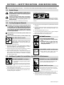
1-1. Symbol Usage
DANGER! − Indicates a hazardous situation which, if
not avoided, will result in death or serious injury. The
possible hazards are shown in the adjoining symbols
or explained in the text.
Indicates a hazardous situation which, if not avoided,
could result in death or serious injury. The possible
hazards are shown in the adjoining symbols or ex-
plained in the text.
NOTICE − Indicates statements not related to personal injury.
. Indicates special instructions.
This group of symbols means Warning! Watch Out! ELECTRIC
SHOCK, MOVING PARTS, and HOT PARTS hazards. Consult sym-
bols and related instructions below for necessary actions to avoid the
hazards.
1-2. Cooling Equipment Hazards
The symbols shown below are used throughout this manual
to call attention to and identify possible hazards. When you
see the symbol, watch out, and follow the related instructions
to avoid the hazard. The safety information given below is
only a summary of the more complete safety information
found in the Safety Standards listed in Section 1-5. Read and
follow all Safety Standards.
Only qualified persons should install, operate, maintain, and
repair this unit.
During operation, keep everybody, especially children, away.
Touching live electrical parts can cause fatal shock
s
or severe burns. The input power circuit and machine
internal circuits are also live when power is on
.
Incorrectly installed or improperly grounded equip
-
ment is a hazard.
ELECTRIC SHOCK can kill.
D Do not touch live electrical parts.
D Disconnect input power or stop engine before installing or
servicing this equipment. Lockout/tagout input power according to
OSHA 29 CFR 1910.147 (see Safety Standards).
D Properly install, ground, and operate this equipment according to
its Owner’s Manual and national, state, and local codes.
D Always verify the supply ground − check and be sure that input
power cord ground wire is properly connected to ground terminal in
disconnect box or that cord plug is connected to a properly
grounded receptacle outlet.
D Keep cords dry, free of oil and grease, and protected from hot metal
and sparks.
D Frequently inspect input power cord and ground conductor for
damage or bare wiring – replace immediately if damaged – bare
wiring can kill.
D Turn off all equipment when not in use.
D Use only well-maintained equipment. Repair or replace damaged
parts at once. Maintain unit according to manual.
D Keep all panels and covers securely in place.
HOT PARTS can burn.
D Do not touch hot parts bare handed.
D Allow cooling period before working on equip-
ment.
D To handle hot parts, use proper tools and/or
wear heavy, insulated welding gloves and
clothing to prevent burns.
HOT PARTS can burn.
D Do not touch hot parts bare handed.
D Allow cooling period before working on equip-
ment.
D To handle hot parts, use proper tools and/or
wear heavy, insulated welding gloves and
clothing to prevent burns.
FLYING METAL or DIRT can injure eyes.
D Wear approved safety glasses with side
shields even under your welding helmet.
1-3. Additional Symbols For Installation, Operation, And Maintenance
FALLING EQUIPMENT can injure.
D Use equipment of adequate capacity to lift and
support unit.
D If using lift forks to move unit, be sure forks are
long enough to extend beyond opposite side of
unit.
D Keep equipment (cables and cords) away from moving vehicles
when working from an aerial location.
D Follow the guidelines in the Applications Manual for the Revised
NIOSH Lifting Equation (Publication No. 94−110) when manu-
ally lifting heavy parts or equipment.
OVERUSE can cause OVERHEATING
D Allow cooling period; follow rated duty cycle.
D Do not block or filter airflow to unit.
MOVING PARTS can injure.
D Keep away from moving parts such as fans.
D Keep all doors, panels, covers, and guards
closed and securely in place.
D Have only qualified persons remove doors, panels, covers, or
guards for maintenance and troubleshooting as necessary.
D Reinstall doors, panels, covers, or guards when maintenance is
finished and before reconnecting input power.

OM-231 313 Page 2
READ INSTRUCTIONS.
D Read and follow all labels and the Owner’s
Manual carefully before installing, operating, or
servicing unit. Read the safety information at
the beginning of the manual and in each
section.
D Use only genuine replacement parts from the manufacturer.
D Perform maintenance and service according to the Owner’s
Manuals, industry standards, and national, state, and local codes.
D Read and understand the Safety Data Sheets (SDSs) and the
manufacturer’s instructions for adhesives, coatings, cleaners,
consumables, coolants, degreasers, fluxes, and metals.
1-4. California Proposition 65 Warnings
Welding or cutting equipment produces fumes or gases
which contain chemicals known to the State of California to
cause birth defects and, in some cases, cancer. (California
Health & Safety Code Section 25249.5 et seq.)
This product contains or produces a chemical known to the
state of California to cause cancer or birth defects (or other
reproductive harm). (California Health & Safety Code Section
25249.5 et seq.)
This product contains chemicals, including lead, known to
the state of California to cause cancer, birth defects, or other
reproductive harm. Wash hands after use.
1-5. Principal Safety Standards
Safety in Welding, Cutting, and Allied Processes, ANSI Standard Z49.1,
is available as a free download from the American Welding Society at
http://www.aws.org or purchased from Global Engineering Documents
(phone: 1-877-413-5184, website: www.global.ihs.com).
Safe Practices for the Preparation of Containers and Piping for Welding
and Cutting, American Welding Society Standard AWS F4.1, from Glob-
al Engineering Documents (phone: 1-877-413-5184, website:
www.global.ihs.com).
Safe Practices for Welding and Cutting Containers that have Held Com-
bustibles, American Welding Society Standard AWS A6.0, from Global
Engineering Documents (phone: 1-877-413-5184,
website: www.global.ihs.com).
National Electrical Code, NFPA Standard 70, from National Fire Protec-
tion Association, Quincy, MA 02269 (phone: 1-800-344-3555, website:
www.nfpa.org and www. sparky.org).
Safe Handling of Compressed Gases in Cylinders, CGA Pamphlet P-1,
from Compressed Gas Association, 14501 George Carter Way, Suite
103, Chantilly, VA 20151 (phone: 703-788-2700, website:
www.cganet.com).
Safety in Welding, Cutting, and Allied Processes, CSA Standard
W117.2, from Canadian Standards Association, Standards Sales, 5060
Spectrum Way, Suite 100, Ontario, Canada L4W 5NS (phone:
800-463-6727, website: www.csa-international.org).
Safe Practice For Occupational And Educational Eye And Face Protec-
tion, ANSI Standard Z87.1, from American National Standards Institute,
25 West 43rd Street, New York, NY 10036 (phone: 212-642-4900, web-
site: www.ansi.org).
Standard for Fire Prevention During Welding, Cutting, and Other Hot
Work, NFPA Standard 51B, from National Fire Protection Association,
Quincy, MA 02269 (phone: 1-800-344-3555, website: www.nfpa.org.
OSHA, Occupational Safety and Health Standards for General Indus-
try, Title 29, Code of Federal Regulations (CFR), Part 1910, Subpart Q,
and Part 1926, Subpart J, from U.S. Government Printing Office, Super-
intendent of Documents, P.O. Box 371954, Pittsburgh, PA 15250-7954
(phone: 1-866-512-1800) (there are 10 OSHA Regional Offices—
phone for Region 5, Chicago, is 312-353-2220, website:
www.osha.gov).
Applications Manual for the Revised NIOSH Lifting Equation, The Na-
tional Institute for Occupational Safety and Health (NIOSH), 1600
Clifton Rd, Atlanta, GA 30333 (phone: 1-800-232-4636, website:
www.cdc.gov/NIOSH).

OM-231 313 Page 3
SECTION 2 − CONSIGNES DE SÉCURITÉ − LIRE AVANT UTILISATION
Cooler 2013−10fre
Pour écarter les risques de blessure pour vous−même et pour autrui — lire, appliquer et ranger en lieu sûr ces consignes relatives
aux précautions de sécurité et au mode opératoire.
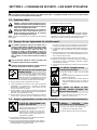
2-1. Symboles utilisés
DANGER! − Indique une situation dangereuse qui si on
l’évite pas peut donner la mort ou des blessures graves.
Les dangers possibles sont montrés par les symboles
joints ou sont expliqués dans le texte.
Indique une situation dangereuse qui si on l’évite pas
peut donner la mort ou des blessures graves. Les
dangers possibles sont montrés par les symboles
joints ou sont expliqués dans le texte.
NOTE − Indique des déclarations pas en relation avec des blessures
personnelles.
. Indique des instructions spécifiques.
Ce groupe de symboles veut dire Avertissement! Attention! DANGER
DE CHOC ELECTRIQUE, PIECES EN MOUVEMENT, et PIECES
CHAUDES. Consulter les symboles et les instructions ci-dessous y
afférant pour les actions nécessaires afin d’éviter le danger.
2-2. Dangers liés aux équipements de refroidissement
Les symboles représentés ci-dessous sont utilisés dans ce
manuel pour attirer l’attention et identifier les dangers possibles.
En présence de l’un de ces symboles, prendre garde et suivre
les instructions afférentes pour éviter tout risque. Les
instructions en matière de sécurité indiquées ci-dessous ne
constituent qu’un sommaire des instructions de sécurité plus
complètes fournies dans les normes de sécurité énumérées
dans la Section 2-5. Lire et observer toutes les normes de
sécurité.
Seul un personnel qualifié est autorisé à installer, faire
fonctionner, entretenir et réparer cet appareil.
Pendant le fonctionnement, maintenir à distance toutes les
personnes, notamment les enfants de l’appareil.
Le contact d’organes électriques sous tension peut
provoquer des accidents mortels ou des brûlures
graves. Le circuit d’alimentation et les circuits
internes de la machine sont également sous tension
lorsque l’alimentation est sur Marche. Un équipement installé ou mis
à la terre de manière incorrecte ou impropre constitue un danger.
UNE DÉCHARGE ÉLECTRIQUE peut
entraîner la mort.
D Ne pas toucher aux pièces électriques sous tension.
D Couper l’alimentation ou arrêter le moteur avant de procéder
à l’installation, à la réparation ou à l’entretien de l’appareil.
Déverrouiller l’alimentation selon la norme OSHA 29 CFR
1910.147 (voir normes de sécurité).
D Installez, mettez à la terre et utilisez correctement cet équipement
conformément à son Manuel d’Utilisation et aux réglementations
nationales, gouvernementales et locales.
D Toujours vérifier la terre du cordon d’alimentation. Vérifier et
s’assurer que le fil de terre du cordon d’alimentation est bien
raccordé à la borne de terre du sectionneur ou que la fiche du
cordon est raccordée à une prise correctement mise à la terre.
D Les câbles doivent être exempts d’humidité, d’huile et de graisse;
protégez−les contre les étincelles et les pièces métalliques
chaudes.
D Vérifier fréquemment le cordon d’alimentation afin de s’assurer
qu’il n’est pas altéré ou à nu, le remplacer immédiatement s’il l’est.
Un fil à nu peut entraîner la mort.
D L’équipement doit être hors tension lorsqu’il n’est pas utilisé.
D N’utiliser qu’un matériel en bon état. Réparer ou remplacer
sur-le-champ les pièces endommagées. Entretenir l’appareil
conformément à ce manuel.
D S’assurer que tous les panneaux et couvercles sont correctement
en place.
LES PIÈCES CHAUDES peuvent
provoquer des brûlures.
D Ne pas toucher à mains nues les parti
es
chaudes.
D Prévoir une période de refroidissement avant
de
travailler à l’équipement.
D Ne pas toucher aux pièces chaudes, utiliser l
es
outils recommandés et porter des gants
de
soudage et des vêtements épais pour éviter l
es
brûlures.
DES PIECES DE METAL ou DES
SALETES peuvent provoquer des
blessures dans les yeux.
D Porter des lunettes de sécurité avec écrans
latéraux ou un écran facial.
2-3. Dangers supplémentaires en relation avec l’installation, le fonctionnement et la maintenanc
e
LA CHUTE DE L’ÉQUIPEMENT peut
provoquer des blessures.
D Utiliser un équipement de levage de capacité
suffisante pour lever l’appareil.
D En utilisant des fourches de levage pour
déplacer l’unité, s’assurer que les fourches
sont suffisamment longues pour dépasser du
côté opposé de l’appareil.
D Tenir l’équipement (câbles et cordons) à distance des véhicules
mobiles lors de toute opération en hauteur.
D Suivre les consignes du Manuel des applications pour l’équation
de levage NIOSH révisée (Publication Nº94–110) lors du levage
manuelle de pièces ou équipements lourds.
L’EMPLOI EXCESSIF peut
SURCHAUFFER L’ÉQUIPEMENT.
D Prévoir une période de refroidissement ;
respecter le cycle opératoire nominal.
D Ne pas obstruer les passages d’air du poste.

OM-231 313 Page 4
Les PIÈCES MOBILES peuvent
causer des blessures.
D S’abstenir de toucher des organes mobiles tels
que des ventilateurs.
D Maintenir fermés et verrouillés les portes,
panneaux, recouvrements et dispositifs de
protection.
D Lorsque cela est nécessaire pour des travaux d’entretien et de
dépannage, faire retirer les portes, panneaux, recouvrements
ou dispositifs de protection uniquement par du personnel
qualifié.
D Remettre les portes, panneaux, recouvrements ou dispositifs de
protection quand l’entretien est terminé et avant de rebrancher
l’alimentation électrique.
LIRE LES INSTRUCTIONS.
D Lire et appliquer les instructions sur les
étiquettes et le Mode d’emploi avant
l’installation, l’utilisation ou l’entretien de
l’appareil. Lire les informations de sécurité au
début du manuel et dans chaque section.
D N’utiliser que les pièces de rechange recommandées par le
constructeur.
D Effectuer l’entretien en respectant les manuels d’utilisation, les
normes industrielles et les codes nationaux, d’état et locaux.
D Lire et comprendre les fiches de données de sécurité et les
instructions du fabricant concernant les adhésifs, les revêtements,
les nettoyants, les consommables, les produits de refroidissement,
les dégraisseurs, les flux et les métaux.
2-4. Proposition californienne 65 Avertissements
Les équipements de soudage et de coupage produisent des
fumées et des gaz qui contiennent des produits chimiques
dont l’État de Californie reconnaît qu’ils provoquent des
malformations congénitales et, dans certains cas, des
cancers. (Code de santé et de sécurité de Californie, chapitre
25249.5 et suivants)
Ce produit contient ou forme un produit chimique reconnu
par l’état de Californie de provoquer le cancer ou
malformations de naissance (ou autre problèmes
reproductifs. (Code de santé et de sécurité de Californie,
chapitre 25249.5 et suivants).
Ce produit contient des produits chimiques, notamment du
plomb, dont l’État de Californie reconnaît qu’ils provoquent
des cancers, des malformations congénitales ou d’autres
problèmes de procréation. Se laver les mains après
utilisation.
2-5. Principales normes de sécurité
Safety in Welding, Cutting, and Allied Processes, ANSI Standard Z49.1,
is available as a free download from the American Welding Society at
http://www.aws.org or purchased from Global Engineering Documents
(phone: 1-877-413-5184, website: www.global.ihs.com).
Safe Practices for the Preparation of Containers and Piping for Welding
and Cutting, American Welding Society Standard AWS F4.1, from
Global Engineering Documents (phone: 1-877-413-5184, website:
www.global.ihs.com).
Safe Practices for Welding and Cutting Containers that have Held
Combustibles, American Welding Society Standard AWS A6.0, from
Global Engineering Documents (phone: 1-877-413-5184,
website: www.global.ihs.com).
National Electrical Code, NFPA Standard 70, from National Fire
Protection Association, Quincy, MA 02269 (phone: 1-800-344-3555,
website: www.nfpa.org and www. sparky.org).
Safe Handling of Compressed Gases in Cylinders, CGA Pamphlet P-1,
from Compressed Gas Association, 14501 George Carter Way, Suite
103, Chantilly, VA 20151 (phone: 703-788-2700, website:
www.cganet.com).
Safety in Welding, Cutting, and Allied Processes, CSA Standard
W117.2, from Canadian Standards Association, Standards Sales, 5060
Spectrum Way, Suite 100, Ontario, Canada L4W 5NS (phone:
800-463-6727, website: www.csa-international.org).
Safe Practice For Occupational And Educational Eye And Face
Protection, ANSI Standard Z87.1, from American National Standards
Institute, 25 West 43rd Street, New York, NY 10036 (phone:
212-642-4900, website: www.ansi.org).
Standard for Fire Prevention During Welding, Cutting, and Other Hot
Work, NFPA Standard 51B, from National Fire Protection Association,
Quincy, MA 02269 (phone: 1-800-344-3555, website: www.nfpa.org.
OSHA, Occupational Safety and Health Standards for General
Industry, Title 29, Code of Federal Regulations (CFR), Part 1910,
Subpart Q, and Part 1926, Subpart J, from U.S. Government Printing
Office, Superintendent of Documents, P.O. Box 371954, Pittsburgh, PA
15250-7954 (phone: 1-866-512-1800) (there are 10 OSHA Regional
Offices—phone for Region 5, Chicago, is 312-353-2220, website:
www.osha.gov).
Applications Manual for the Revised NIOSH Lifting Equation, The
National Institute for Occupational Safety and Health (NIOSH), 1600
Clifton Rd, Atlanta, GA 30333 (phone: 1-800-232-4636, website:
www.cdc.gov/NIOSH).

. A complete Parts List is available at www.MillerWelds.com
OM-231 313 Page 5
SECTION 3 − DEFINITIONS
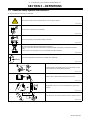
3-1. Additional Safety Symbols And Definitions
. Some symbols are found only on CE products.
Warning! Watch Out! There are possible hazards as shown by the symbols.
Safe1 2012−05
Do not remove or paint over (cover) the label.
Safe20 2012−05
Disconnect input plug or power before working on machine.
Safe30 2012−05
Do not discard product (where applicable) with general waste.
Reuse or recycle Waste Electrical and Electronic Equipment (WEEE) by disposing at a designated collection
facility.
Contact your local recycling office or your local distributor for further information.
Safe37 2012−05
XXXXX
Use coolant suggested by the manufacturer: 043810 (HF), 043809 (Al).
Safe52 2012−05
Read the labels on the welding power source, wire feeder, or other
major equipment for welding safety information.
Safe71 2012−06
Read the Owner’s Manual before working on this machine.
Safe70 2012−06
Safe50 2012−05
Plugged filter or hoses can cause overheating to the power source
and torch.
100 h. Std.
Safe51 2012−05
Every 100 hours, check and clean filter and check condition of hoses.

. A complete Parts List is available at www.MillerWelds.com
OM-231 313 Page 6
3-2. Miscellaneous Symbols And Definitions
. Some symbols are found only on CE products.
Hz
Hertz
Input Power
Power On
Indicator
Water (Coolant)
Output
Water (Coolant)
Input
Line Connection
Single-Phase
Alternating
Current
U
1
Primary Voltage
I
1max
Rated Maximum
Supply Current
IP
Degree Of
Protection
P
max
Rated maximum
power
Pl/
min
Power liters per
minute
Notes

. A complete Parts List is available at www.MillerWelds.com
OM-231 313 Page 7
SECTION 4 − SPECIFICATIONS
4-1. Serial Number And Rating Label Location
The serial number and rating information for this product is located on the front panel. Use rating label to determine input power requirements and/or
rated output. For future reference, write serial number in space provided on cover of this manual.
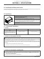
4-2. Specifications
804 839-A
Recirculating Coolant System For Water-Cooled GTAW Torches And GMAW Guns.
Use With Guns/Torches Rated Up To 600 Amperes.
3-1/2 gal (13.2 L) Coolant Tank Capacity;
Maximum Cooling Capacity: 4,140 W (14,000 BTU/hr) @ 5.0 qt/min (4.7 L/min)
IEC Cooling Capacity: 1,660 W (5,660 BTU/hr) @ 1.1 qt/min (1 L/min)
IEC Cooling Capacity States That The Water Inlet Temperature Cannot Exceed 40° C Above Ambient
Temperature At A 1l/ Min Flow Rate. Ratings Developed At An Ambient Temperature Of 68° F to 77° F
(20° C To 25° C). Operating Temperature Is 14° F To 104° F (−10° C To 40° C)
Dimensions: 26 in. (660 mm) Long, 15-3/4 in. (400 mm) Wide, 11-3/4 in. (298 mm) High
Weight: 60 lb (27 kg)
115 Volt Models Use 5.9 Amperes, 60 Hertz, 4.7 Amperes 50 Hz, Single-Phase Input Power
4-3. Environmental Specifications
A. IP Rating
IP Rating Operating Temperature Range Storage Temperature Range
IP23
This equipment is designed for outdoor use. It
may be stored, but is not intended to be used
for welding outside during precipitation unless
sheltered.
14 to 104 °F (-10 to 40°C)
-4 to 131 °F (-20 to 55°C)
IP23 2014−06
B. Information On Electromagnetic Fields (EMF)
! This equipment shall not be used by the general public as the EMF limits for the general public might be exceeded during welding.
This equipment is built in accordance with EN 60974−1 and is intended to be used only in an occupational environment (where the general public
access is prohibited or regulated in such a way as to be similar to occupational use) by an expert or an instructed person.
Wire feeders and ancillary equipment (such as torches, liquid cooling systems and arc striking and stabilizing devices) as part of the welding
circuit may not be a major contributor to the EMF. See the Owner’s Manuals for all components of the welding circuit for additional EMF exposure
information.
S The EMF assessment on this equipment was conducted at 0.5 meter.
S At a distance of 1 meter the EMF exposure values were less than 20% of the permissible values.
ce-emf 1 2010-10
C. Information On Electromagnetic Compatibility (EMC)
! This Class A equipment is not intended for use in residential locations where the electrical power is provided by the public low−
voltage supply system. There can be potential difficulties in ensuring electromagnetic compatibility in those locations, due to con-
ducted as well as radiated disturbances.
This equipment complies with IEC 61000-3-11 and IEC 61000-3-12.
ce-emc 4 2014-07

. A complete Parts List is available at www.MillerWelds.com
OM-231 313 Page 8
4-4. Coolant Chart
Low Conductivity Coolant No. 043 810**; Distilled Or Deionized Water OK Above 32° F (0° C)
GTAW Or Where
HF* Is Used
Application
*HF: High Frequency Current
**Coolant 043 810, a 50/50 solution, protects to -37° F (-38°C) and resist algae growth.
Coolant
NOTICE − Use of any coolant other than that listed in the table voids the warranty on any parts that come in contact with the coolant (pump,
radiator, etc.).
Notes

. A complete Parts List is available at www.MillerWelds.com
OM-231 313 Page 9
SECTION 5 − INSTALLATION
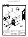
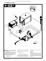
5-1. GTAW Connections
804 846-A
Tools Needed:
5/8 in.
1
2
3
4
! Do not move or operate unit where
it could tip.
To prevent overheating, make sure cooling
unit is positioned so airflow is not restricted.
NOTICE − If welding power source has a
water valve, do not connect hoses to water
valve. Connect hoses as shown.
1 Coolant Out Hose
2 Coolant In Hose
Fittings have 5/8-18 left-hand threads.
Connect hoses with proper fittings as
shown. Some power sources may require
a TIG block.
3 Coolant Tank Cap
4 115 Volt AC Grounded Receptacle
An individual branch circuit capable of car-
rying 15 amperes and protected by fuses
or circuit breakers is recommended. Rec-
ommended fuse or circuit breaker size is
15 amperes.
Operation:
Fill tank with proper coolant. Use table in
Section 4-4 to select proper coolant. Main-
tain coolant level at approximately 1 in (25
mm) below top of filler neck. Connect
hoses as shown. Unit turns on when
plugged in.

. A complete Parts List is available at www.MillerWelds.com
OM-231 313 Page 10
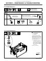
5-2. GMAW Connections
804 845-A
Tools Needed:
5/8 in.
! Do not move or operate unit where
it could tip.
To prevent overheating, make sure cooling
unit is positioned so airflow is not restricted.
NOTICE − If welding power source has a
water valve, do not connect hoses to water
valve. Connect hoses as shown.
1 Coolant Out Hose
2 Coolant In Hose
Fittings have 5/8-18 left-hand threads.
Connect hoses with proper fittings as
shown.
3 Coolant Tank Cap
4 115 Volt AC Grounded Receptacle
An individual branch circuit capable of car-
rying 15 amperes and protected by fuses
or circuit breakers is recommended. Rec-
ommended fuse or circuit breaker size is
15 amperes.
Operation:
Fill tank with proper coolant. Use table in
Section 4-4 to select proper coolant. Main-
tain coolant level at approximately 1 in (25
mm) below top of filler neck. Connect
hoses as shown. Unit turns on when
plugged in.
2
1
3
4

. A complete Parts List is available at www.MillerWelds.com
OM-231 313 Page 11
SECTION 6 − MAINTENANCE & TROUBLESHOOTING
6-1. Routine Maintenance
! Disconnect power
before maintaining.
n = Check Z = Change ~ = Clean Δ = Repair l = Replace
* To be done by Factory Authorized Service Agent
Every
3
Months
~Coolant Strainer,
durning heavy service,
clean more frequently.
~ Blow out heat exchanger fins.
nCheck coolant level. Top off with
distilled or deionized water if necessary.
Every
6
Months
nlHoses
nl Labels
ZReplace coolant.
m30 Torx
Tools Needed:
6-2. Coolant Maintenance
804 649-A
! Disconnect input power be-
fore maintaining.
1 Coolant Filter
Unscrew housing to clean filter.
Changing coolant: Drain coolant by
tipping unit to rear, or use suction
pump. Fill with clean water and run
for 10 minutes. Drain and refill with
coolant (see section 4-4).
. If replacing hoses, use hoses
compatible with ethylene gly-
col, such as Buna-n, Neo-
prene, or Hypalon. Oxy-acety-
lene hoses are not compatible
with any product containing
ethylene glycol.
Install cover if removed.
1

. A complete Parts List is available at www.MillerWelds.com
OM-231 313 Page 12
6-3. Troubleshooting
Trouble Remedy
Coolant system does not work. Be sure input power cord is plugged in to energized receptacle.
Check line fuses or circuit breaker, and replace or reset if necessary.
Motor overheated. Unit starts running when motor has cooled.
Have Factory Authorized Service Agent check Power switch S1 and motor (Mot).
Decreased or no coolant flow. Add coolant.
Check for clogged hoses or coolant filter. Clean filter or clean / replace hoses if necessary.
Disconnect pump, and check for sheared coupling. Replace coupling if necessary.
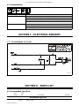
SECTION 7 − ELECTRICAL DIAGRAM
7-1. Circuit Diagram For Cooler
228 525-B
SECTION 8 − PARTS LIST
8-1. Recommended Spare Parts
Description
Part
No.
Dia.
Mkgs.
Recommended Spare Parts
Quantity
257415 Screen, Filter 1................ .... ..................................................


Effective January 1, 2015
(Equipment with a serial number preface of MF or newer)
This limited warranty supersedes all previous Miller warranties and is exclusive with no other
guarantees or warranties expressed or implied.
LIMITED WARRANTY − Subject to the terms and conditions below,
Miller Electric Mfg. Co., Appleton, Wisconsin, warrants to its original
retail purchaser that new Miller equipment sold after the effective
date of this limited warranty is free of defects in material and
workmanship at the time it is shipped by Miller. THIS WARRANTY IS
EXPRESSLY IN LIEU OF ALL OTHER WARRANTIES, EXPRESS
OR IMPLIED, INCLUDING THE WARRANTIES OF
MERCHANTABILITY AND FITNESS.
Within the warranty periods listed below, Miller will repair or replace
any warranted parts or components that fail due to such defects in
material or workmanship. Miller must be notified in writing within
thirty (30) days of such defect or failure, at which time Miller will
provide instructions on the warranty claim procedures to be
followed. If notification is submitted as an online warranty claim, the
claim must include a detailed description of the fault and the
troubleshooting steps taken to identify failed components and the
cause of their failure.
Miller shall honor warranty claims on warranted equipment listed
below in the event of such a failure within the warranty time periods.
All warranty time periods start on the delivery date of the equipment
to the original end-user purchaser, and not to exceed twelve months
after the equipment is shipped to a North American distributor or
eighteen months after the equipment is shipped to an International
distributor.
1. 5 Years Parts — 3 Years Labor
* Original Main Power Rectifiers Only to Include SCRs,
Diodes, and Discrete Rectifier Modules
2. 3 Years — Parts and Labor
* Auto-Darkening Helmet Lenses (Except Classic
Series) (No Labor)
* Engine Driven Welder/Generators
(NOTE: Engines are Warranted Separately by the
Engine Manufacturer.)
* Inverter Power Sources (Unless Otherwise Stated)
* Plasma Arc Cutting Power Sources
* Process Controllers
* Semi-Automatic and Automatic Wire Feeders
* Transformer/Rectifier Power Sources
3. 2 Years — Parts and Labor
* Auto-Darkening Helmet Lenses − Classic Series Only
(No Labor)
* Fume Extractors − Capture 5, Filtair 400 and Industrial
Collector Series
4. 1 Year — Parts and Labor Unless Specified
* Automatic Motion Devices
* CoolBelt and CoolBand Blower Unit (No Labor)
* Desiccant Air Dryer System
* External Monitoring Equipment and Sensors
* Field Options
(NOTE: Field options are covered for the remaining
warranty period of the product they are installed in, or
for a minimum of one year — whichever is greater.)
* RFCS Foot Controls (Except RFCS-RJ45)
* Fume Extractors − Filtair 130, MWX and SWX Series
* HF Units
* ICE/XT Plasma Cutting Torches (No Labor)
* Induction Heating Power Sources, Coolers
(NOTE: Digital Recorders are Warranted Separately
by the Manufacturer.)
* LiveArc Welding Performance Management System
* Load Banks
* Motor-Driven Guns (except Spoolmate Spoolguns)
* PAPR Blower Unit (No Labor)
* Positioners and Controllers
* Racks
* Running Gear/Trailers
* Spot Welders
* Subarc Wire Drive Assemblies
* Water Coolant Systems
* TIG Torches (No Labor)
* Wireless Remote Foot/Hand Controls and Receivers
* Work Stations/Weld Tables (No Labor)
5. 6 Months — Parts
* Batteries
* Bernard Guns (No Labor)
* Tregaskiss Guns (No Labor)
6. 90 Days — Parts
* Accessory (Kits)
* Canvas Covers
* Induction Heating Coils and Blankets, Cables, and
Non-Electronic Controls
* M-Guns
* MIG Guns and Subarc (SAW) Torches
* Remote Controls and RFCS-RJ45
* Replacement Parts (No labor)
* Roughneck Guns
* Spoolmate Spoolguns
Miller’s True Blue® Limited Warranty shall not apply to:
1. Consumable components; such as contact tips,
cutting nozzles, contactors, brushes, relays, work
station table tops and welding curtains, or parts that
fail due to normal wear. (Exception: brushes and
relays are covered on all engine-driven products.)
2. Items furnished by Miller, but manufactured by others,
such as engines or trade accessories. These items are
covered by the manufacturer’s warranty, if any.
3. Equipment that has been modified by any party other than
Miller, or equipment that has been improperly installed,
improperly operated or misused based upon industry
standards, or equipment which has not had reasonable
and necessary maintenance, or equipment which has
been used for operation outside of the specifications for
the equipment.
MILLER PRODUCTS ARE INTENDED FOR PURCHASE AND
USE BY COMMERCIAL/INDUSTRIAL USERS AND PERSONS
TRAINED AND EXPERIENCED IN THE USE AND
MAINTENANCE OF WELDING EQUIPMENT.
In the event of a warranty claim covered by this warranty, the
exclusive remedies shall be, at Miller’s option: (1) repair; or (2)
replacement; or, where authorized in writing by Miller in appropriate
cases, (3) the reasonable cost of repair or replacement at an
authorized Miller service station; or (4) payment of or credit for the
purchase price (less reasonable depreciation based upon actual
use) upon return of the goods at customer’s risk and expense.
Miller’s option of repair or replacement will be F.O.B., Factory at
Appleton, Wisconsin, or F.O.B. at a Miller authorized service facility
as determined by Miller. Therefore no compensation or
reimbursement for transportation costs of any kind will be allowed.
TO THE EXTENT PERMITTED BY LAW, THE REMEDIES
PROVIDED HEREIN ARE THE SOLE AND EXCLUSIVE
REMEDIES. IN NO EVENT SHALL MILLER BE LIABLE FOR
DIRECT, INDIRECT, SPECIAL, INCIDENTAL OR
CONSEQUENTIAL DAMAGES (INCLUDING LOSS OF PROFIT),
WHETHER BASED ON CONTRACT, TORT OR ANY OTHER
LEGAL THEORY.
ANY EXPRESS WARRANTY NOT PROVIDED HEREIN AND ANY
IMPLIED WARRANTY, GUARANTY OR REPRESENTATION AS
TO PERFORMANCE, AND ANY REMEDY FOR BREACH OF
CONTRACT TORT OR ANY OTHER LEGAL THEORY WHICH,
BUT FOR THIS PROVISION, MIGHT ARISE BY IMPLICATION,
OPERATION OF LAW, CUSTOM OF TRADE OR COURSE OF
DEALING, INCLUDING ANY IMPLIED WARRANTY OF
MERCHANTABILITY OR FITNESS FOR PARTICULAR
PURPOSE, WITH RESPECT TO ANY AND ALL EQUIPMENT
FURNISHED BY MILLER IS EXCLUDED AND DISCLAIMED BY
MILLER.
Some states in the U.S.A. do not allow limitations of how long an
implied warranty lasts, or the exclusion of incidental, indirect,
special or consequential damages, so the above limitation or
exclusion may not apply to you. This warranty provides specific
legal rights, and other rights may be available, but may vary from
state to state.
In Canada, legislation in some provinces provides for certain
additional warranties or remedies other than as stated herein, and to
the extent that they may not be waived, the limitations and
exclusions set out above may not apply. This Limited Warranty
provides specific legal rights, and other rights may be available, but
may vary from province to province.
Warranty Questions?
Call
1-800-4-A-MILLER
for your local
Miller distributor.
miller_warr 2015-01
Your distributor also gives
you ...
Service
You always get the fast,
reliable response you
need. Most replacement
parts can be in your
hands in 24 hours.
Support
Need fast answers to the
tough welding questions?
Contact your distributor.
The expertise of the
distributor and Miller is
there to help you, every
step of the way.

ORIGINAL INSTRUCTIONS − PRINTED IN USA © 2015 Miller Electric Mfg. Co. 2015−01
Miller Electric Mfg. Co.
An Illinois Tool Works Company
1635 West Spencer Street
Appleton, WI 54914 USA
International Headquarters−USA
USA Phone: 920-735-4505 Auto-Attended
USA & Canada FAX: 920-735-4134
International FAX: 920-735-4125
For International Locations Visit
www.MillerWelds.com
Model Name Serial/Style Number
Purchase Date (Date which equipment was delivered to original customer.)
Distributor
Address
City
State Zip
Please complete and retain with your personal records.
Always provide Model Name and Serial/Style Number.
Contact a DISTRIBUTOR or SERVICE AGENCY near you.
Welding Supplies and Consumables
Options and Accessories
Personal Safety Equipment
Service and Repair
Replacement Parts
Training (Schools, Videos, Books)
Technical Manuals (Servicing Information
and Parts)
Circuit Diagrams
Welding Process Handbooks
Contact the Delivering Carrier to:
For Service
Owner’s Record
File a claim for loss or damage during
shipment.
For assistance in filing or settling claims, contact
your distributor and/or equipment manufacturer’s
Transportation Department.
Contact your Distributor for:
To locate a Distributor or Service Agency visit
www.millerwelds.com or call 1-800-4-A-Miller
-
 1
1
-
 2
2
-
 3
3
-
 4
4
-
 5
5
-
 6
6
-
 7
7
-
 8
8
-
 9
9
-
 10
10
-
 11
11
-
 12
12
-
 13
13
-
 14
14
-
 15
15
-
 16
16
-
 17
17
-
 18
18
-
 19
19
-
 20
20


Miller Coolmate 3.5 Le manuel du propriétaire
- Catégorie
- Système de soudage
- Taper
- Le manuel du propriétaire
- Ce manuel convient également à
dans d''autres langues
- English: Miller Coolmate 3.5 Owner's manual
Documents connexes
-
Miller MG050034L Le manuel du propriétaire
-
-
-
Miller MC170519J Le manuel du propriétaire
-
-
-
Miller MH350424L Le manuel du propriétaire
-
-
Miller COOL RUNNER 3CS Le manuel du propriétaire
-