Simplicity MANUAL, OPERATOR'S AND INSTALLATION Manuel utilisateur
- Catégorie
- Groupes électrogènes
- Taper
- Manuel utilisateur

Generator for Standby and Non-Emergency Use, Models: 17kW -
26kW
Installation and Operation Manual
Manual de instalación y operación
Manuel d’installation et d’utilisation
This generator is rated in accordance with UL (Underwriters Laboratories) 2200 (stationary engine generator assemblies) and
CSA (Canadian Standards Association) standard C22.2 N. 100-14 (motors and generators).
Este grupo electrógeno está clasificado conforme a la norma UL (Underwriters Laboratories) 2200 (conjuntos de grupos
electrógenos con motores fijos) y a la norma CSA (Canadian Standards Association) C22.2 N. 100-14 (motores y grupos electrógenos).
Ce groupe électrogène est certifié UL (Underwriters Laboratories) 2200 (groupes électrogènes à moteur fixe) et conforme à la
norme CSA (Canadian Standards Association) C22.2 N. 100-14 (moteurs et groupes électrogènes).
© 2023 Briggs & Stratton. All rights reserved. 80126266
Revision A
Not for
Reproduction

Manual Contents:
Important Safety Instructions..............................................2
General Information..............................................................3
Installation............................................................................. 5
Operation............................................................................. 21
Maintenance.........................................................................25
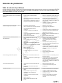
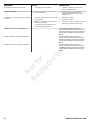
Troubleshooting..................................................................32
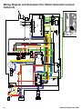
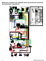
Wiring Diagram and Schematic(For Starter Solenoid
Location: Callout A)............................................................34
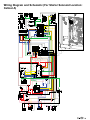
Wiring Diagram and Schematic(For Starter Solenoid
Location: Callout A)............................................................35
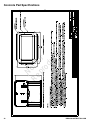
Concrete Pad Specifications............................................. 36
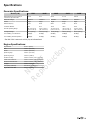
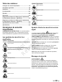
Specifications......................................................................37
Important Safety Instructions
SAVE THESE INSTRUCTIONS - This manual contains
important instructions that must be read, understood,
and obeyed during installation of generator kits and/or
accessories.
Safety Symbols and Meanings
Symbol Meaning
Safety alert symbol shows a possiblepersonal injury hazard.
Read Manual. Failure to obey warnings, instructions,
installation manual, andOperator’sManual could result in
death or serious injury.
Explosion
Electric Shock
Auto-start
Fire
Chemical Burn
Symbol Meaning
Toxic Fume
Eye Protection
Hot Surface
Rotating Parts
Safety Alert Symbol and Signal Words
The safety alert symbol identifies safety information
about hazards that could result in personal injury. A signal
word (DANGER, WARNING, or CAUTION) is used to
indicate the likelihood and the potential severity of injury. In
addition, a hazard symbol is used to represent the type of
hazard.
DANGER indicates a hazard which, if not avoided, will result
in death or serious injury.
WARNING indicates a hazard which, if not avoided, could
result in death or serious injury.
CAUTION indicates a hazard which, if not avoided, could
result in minor or moderate injury.
NOTICE indicates information considered important but not
hazard-related.
Safety Messages
WARNING
This product can expose you to chemicals including used
engine oil, which is known to the State of California to cause
cancer, and carbon monoxide, which is known to the State of
California to cause birth defects or other reproductive harm.
For more information go towww.P65Warnings.ca.gov.
WARNING
This product contains lead and lead compounds,
known to the state of California to cause birth defects
or other reproductive harm. Wash your hands after
handling this product. Cancer and Reproductive Harm -
www.P65Warnings.ca.gov.
2 BRIGGSandSTRATTON.COM
Not for
Reproduction

NOTICE: Improper treatment of generator could damage it
and shorten its life.
• Use generator only for intended uses. See Product Use
section of this manual.
• If you have questions about the intended use, contact
your authorized dealer.
• Operate the generator only on level surfaces.
• Adequate, unobstructed flow of cooling and ventilating
air is critical for correct generator operation.
• The access panels/doors must be installed whenever
the unit is running.
• DO NOT expose the generator to excessive moisture,
dust, dirt, or corrosive vapor.
• Remain alert at all times while working on this
equipment. Never work on the equipment when you are
physically or mentally fatigued.
• DO NOT insert any objects through the cooling slots.
• DO NOT use the generator or any of its parts as a step.
Stepping on the unit could cause stress and break parts.
This may result in dangerous operating conditions from
leaking exhaust gases, fuel leakage, oil leakage, etc.
• Shut off generator if:
• electrical output is lost.
• equipment sparks, smokes, or emits flames.
• unit vibrates excessively or makes unusual noises.
FCCStatementPart15(ToUser)
Pursuant to part 15.21 of the FCC Rules, you are
cautioned that changesor modificationsto the product
notexpresslyapproved by Briggs & Strattoncouldvoid
yourauthority to operate the product.
This devicecomplies withpart 15 of the FCC Rules.
Operationis subjectto thefollowing two conditions:(1) This
device may notcauseharmfulinterference, and (2) this
device must acceptanyinterference received,including
interferencethatmaycause undesiredoperation.
This equipment has been tested and found
tocomplywith the limits for a Class B digital device,
pursuant to part 15 of the FCC Rules. These limits
aredesignedtoprovidereasonableprotection
againstharmfulinterference in a residential installation.
This equipment generates, uses and can radiate radio
frequency energy and, if not installed and usedin accordance
withthe instructions,maycauseharmfulinterference to
radio communications. However, there is no guarantee that
interference will not occur in aparticularinstallation. If this
equipmentdoescauseharmfulinterference to radio or
television reception, which can be determined by turning the
equipment off and on, the user is encouraged to try to correct
the interference by one or more of thefollowing measures:
• Reorient or relocate the receiving antenna.
• Increase the separation between the equipment and
receiver.
• Connect the equipment into an outlet on a circuit
different from that to which the receiver is connected.
• Consult the dealer or an experienced radio/TV
technician for help.
General Information
For most applications, the Installation and Operation Manual
contains the informationnecessaryto correctly install,
operate, and maintain the generator. Briggs & Stratton has
made every effort tomake surethat the information in this
manual is accurate and current. Briggs & Stratton reserves
the right to change, alter, or otherwise improve the product
and this document at any time without prior notice.
Thank You
Thank you for purchasing this quality-built Briggs & Stratton®
generator. We are pleased that you have placed your
confidence in the Briggs & Stratton brand. When operated
and maintained according to the instructions in this manual,
your generator can provide many years of dependable
service. This manual contains safety information to make
you aware of the hazards and risks associated with standby
generators and how to avoid them.
SAVE THESE INSTRUCTIONS. This manual contains
important instructions that users must obey during installation,
operation, and maintenance of the generator and battery.
Where to Find Us
Youdo nothave to look far to find support and service for
your equipment. There are many authorized service dealers
worldwide thatsupplyquality service. You can also contact
Customer Service by phone at 800-732-2989 between 8:00
AM and 5:00 PM central time or click on "Dealer Locator"
at www.briggsandstratton.com, which will supplya list of
authorized dealers.
For Future Reference
Fill out the information that follows and keep it with your
receipt. Have this information at hand if you need to contact
your installer or authorized dealer regarding service or repair
of the unit.
Date of Purchase: ________________________________
Dealer/Retailer: _________________________________
Dealer's/Retailer'sPhone Number: __________________
GENERATOR:
Model Number: ____________________________
Model Revision: ____________________________
Serial Number: ____________________________
ENGINE:
Model Number: __________________________________
3
Not for
Reproduction

Serial Number: ___________________________________
Equipment Description and Product Use
These generators are EPA certified for optional standby
applications. Non-Emergency generator use is intended
for non-emergency demand response use and optional
standby applications. Optional standby provides an alternate
source of electric power and serves loads such as heating,
refrigeration systems, and communication systems that,
when stopped during a power outage, can cause discomfort
or inconvenience. Non-emergency generators used for
demand response are an energy source for electrical utility or
cooperative providers to rely on during peak demand times or
dispatched during capacity congestion.
NOTICE: Generator models do NOT qualify for either an
emergency standby or legally required standby system as
defined by NFPA 70 (NEC).
• Emergency generator systems are intended to
automatically supply illumination, power, or both, to
designated areas and equipment in the event of failure
of the normal supply. Emergency systems can also
supply power for such functions as ventilation where
essential to maintain life, where current interruption of
the normal supply would produce serious life safety or
health hazards.
• Legally required standby generator systems are
intended to automatically supply power to selected
loads in the event of failure of the normal source (which
can create hazards or prevent rescue or fire-fighting
operations).
Installer Responsibilities
• Read and obey the safety, installation and operation
instructions in this Installation and Operation Manual.
• Install only aNationally Recognized Testing Laboratory
(NRTL) approved transfer switch that is compatible with
the generator.
• Installation must obey all applicable codes, industry
standards, laws, and regulations.
• Allow sufficient room on all sides of the generator for
maintenance and service.
• Speak with the owner about generator placement.
• Speak with the owner aboutcarbon monoxide (CO)and
smoke detectors. It is the owner's responsibility to have
carbon monoxide and smoke detector(s) installed and
maintained indoors according to the manufacturer’s
instructions and recommendations.
• Make sure that ALL of the manuals are given to the
owner after the installation has been completed.
• The unit is to be installed so that the risk of contact by
people is minimized.
Owner Responsibilities
• Read and obey the instructions in this Installation and
Operation Manual.
• Follow a regular maintenance schedule and use the
generator as specified in this manual.
• Carbon monoxide detector(s) MUST be installed and
maintained indoors according to the manufacturer’s
instructions and recommendations. Smoke alarms
cannot detect carbon monoxide gas.
• Smoke detector(s) MUST be installed and maintained
indoors according to the manufacturer’s instructions and
recommendations. Carbon monoxide alarms cannot
detect smoke.
Installation Factors to Consider
The illustrations shown in this manual depict typical
circumstances. They are meant to familiarize you with the
installation options available for the generator.
Always consider installation factors such as federal and local
codes, appearance, noise levels, fuel types, and distances.
As the distance increases from the existing electrical service
and gaseous fuel supply, and the number of bends in the
fuel supply increases, installers must make compensations
for piping and wiring materials. These compensations are
necessary to comply with local codes and overcome drops in
electrical voltage and drops in gaseous fuel pressure.
Delivery Inspection
Avoid damage from dropping, bumping, or collision with the
shipping carton.
Remove the carton and carefullyexaminethe generator for
damage thatcanoccur during shipment.
If an owner sees loss or damageat the time of delivery, the
ownermusttellthe person or persons who made the delivery
to document the loss or damage on the freight bill and affix
a signature under the consignor’s memo of loss or damage.
If the owner notices loss or damage after delivery, separate
the damaged materials and then contact the carrier for claim
procedures. Missing or damaged parts are not warranted.
Shipment Contents
The generator system is supplied with:
• Oil (5W30 Full Synthetic)
• Flexible fuel line
• Fuel pipe coupling
•Quick Operation Manual
•Installation and Operation Manual
• Product and emissions warranty booklet
• Two access keys (generator is shipped withaset of
identical keys fastened to one of the end caps)
• Two 15 amp ATO-type fuses
• Four lifting hole caps
The generator system does not included (An owner will
need to purchase before installation):
• Carbon monoxide detectors
• Smoke detectors
• Starting battery
4 BRIGGSandSTRATTON.COM
Not for
Reproduction

• Connecting wire and conduit
• Fuel supply valves and plumbing
• Crane, lifting straps, chains or cables
• Two 60 in (152.4 cm) lengths of .75 in (1.9 cm) nominal
minimum Schedule 40 steel pipe (NOT conduit)
• Torque screwdriver, 5 to 50 inch-pound (0.6 to5.6N·m)
range
• Multimeter
Installation
WARNING
Generator and utility voltage could cause electrical shock or
burn resulting in death or serious injury.
• Installation must be performed by a licensed
professional.
• Disconnect all sources of electricity before installing or
servicing equipment.
• Ground system before applying power.
WARNING
Hazardous Voltage - Installing low and high voltage wire in
same conduit could cause electric shock or burns, resulting in
death or serious injury.
• Do not run low and high voltage wire in the same
conduit unless the insulation rating on ALL wiring is
rated for 600 V. See NFPA 70 for more information.
Only current licensed electrical professionalsare
qualified to dosystem installations. Installations must
obeyallrelatedcodes, industry standards and regulations.
The equipment warranty is VOID unless the system is
installed by licensed electricalprofessionals.
NOTICEDisconnect all power connections before you install
this equipment. Failure to do so could cause internal damage
to the board during electrical connections.
Incorrect installation can cause damage to the circuit boards
and shorten their life. If you install the circuit boards in live
circuits it will damage the board, which is not included in the
warranty. ALWAYS disconnect ALL sources of power before
you service the generator.
All wiring must be the correct gauge, correctly supported and
protected by conduit. All wiring must be done as specified
by federal, state and local codes, standards and regulations.
Obey the wire type and torque specifications printed on the
terminal blocks, neutral/ground connectors, and installation
instructions. Use the installer supplied 600VAC or greater
copper or aluminum wire of a gauge that complies with the
latest version of the National Electric Code to complete the
connections between utility power, transfer switch, generator,
main distribution panel, and optional remote modules. Apply
the necessary correction factors and wire size calculations.
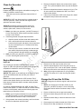
1. Set the Generator Circuit Breaker to the OFF position.
2. Set the Generator ON/OFF Switch to the OFF position.
3. Remove the 15 Amp fuse from the generator.
4. Disconnect the utility power to the generator and transfer
switch.
Generator Placement
Beforethe generator is installed, speak with the owner and
convey the requirements that follow. They must be satisfied
before the installation is complete.
The owner must be told about twoequally important
safetyconcerns:
• Carbon monoxide poisoning
• Fire
An installer must meet several other general location
guidelines that are contained in this manualbefore the
installation is complete.
WARNING
Engine exhaust contains carbon monoxide, a poisonous gas
that could kill you in minutes. You cannot smell it, see it, or
taste it. Even if you do not smell exhaust fumes, you could
still be exposed to carbon monoxide gas.
• Operate this product ONLY outdoors in an area that will
not accumulate deadly exhaust gas.
• Direct exhaust gas away from any windows, doors,
ventilation intakes, soffit vents, crawl spaces, open
garage doors or other openings that can allow exhaust
gas to enter inside or be drawn into a potentially
occupied building or structure.
• Carbon monoxide detector(s) MUST be installed and
maintained indoors according to the manufacturer’s
instructions/recommendations. Smoke alarms cannot
detect carbon monoxide gas.
• If you start to feel sick, dizzy, weak, or your carbon
monoxide alarm sounds while using this product, get to
fresh air right away. Call emergency services. You may
have carbon monoxide poisoning.
• DO NOT run this product inside homes, garages,
basements, crawlspaces, sheds, or other partially-
enclosed spaces even if using fans or opening doors
and windows for ventilation. Carbon monoxide can
quickly build up in these spaces and can linger for
hours, even after this product has shut off.
5
Not for
Reproduction

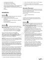
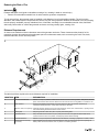
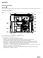
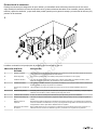
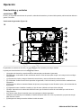
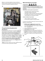
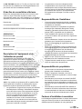
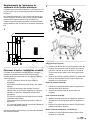
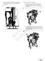
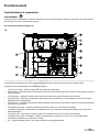
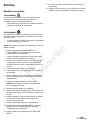
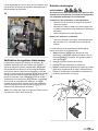
1
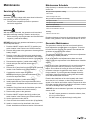
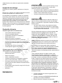
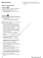
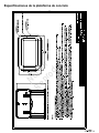
• (A)Exhaust outlet side of enclosure.
• (B)Air inlet side of enclosure.
• (C) Front of enclosure.
• (D) Back of enclosure.
Generator Location Considerations
The installation location of the generator directly effects:
1. The amount and size of the plumbing required to fuel the
generator.
2. The amount and size of the wiring required to control and
connect the generator.
3. The safety of the installation regarding exhaust gas and
carbon monoxide hazards, fire risks, proximity to other
utilities, and exposure to weather elements.
The Generator Placement section addresses specific location
guidelines. The owner and installer must speak to one
another to determine how the site can affect installation costs
and compliance with local codes and standards.
Federal and International Standards
Generator installation must strictly adhere to ICC, IFGC,
NFPA 37, NFPA 54, NFPA 58, and NFPA 70 standards.
National Fire Protection Association (NFPA) 37: This
standard addresses the installation and use of stationary
combustion engines. Its requirements describe keeping
an enclosed generator a specific distance from a structure
or wall. This standard also requires that when you locate
a generator, you provide adequate space to perform
maintenance and repair tasks and space for the maneuvering
of first responders.
NFPA 37, Section 4.1.4, Engines Located Outdoors: This
requirement specifies that engines and their weatherproof
housings (if provided) installed outdoors must remain at least
5 ft (1.52 m) from openings in walls and at least 5 ft (1.52 m)
from structures with combustible walls. The standard does
not require a minimum separation if either of the following
conditions exist:
1. The structure’s adjacent wall has a fire-resistance rating
of at least one hour.
2. Where a fire test involving consumption of the available
combustibles, within the engine or, if provided, its
weatherproof housing demonstrates that a fire originating
at the engine or its weatherproof housing will not ignite
combustible structures.
Annex A—Explanatory Material
A4.1.4 (2): This requirement means that demonstrating
compliance involves conducting a full-scale fire test or by
followingthe calculation procedures found in Chapter 10 of
NFPA 555.
This requirement concludes that due to the limited space
frequently available for installation of the unit, exception (2) is
beneficial for many residential and commercial installations.
The manufacturer has contracted with an independent testing
laboratory to conduct full-scale fire tests.
The ultimate goal of the fire testing was to evaluate the
absolute worst fire scenario within the generator andto
determine the ignition risk foritems outside the engine
enclosure at specific distances. Note that the enclosure is
constructed of non-combustible materials. Outcomes from
independent lab tests showed that a fire that started within
the generator enclosure would not pose an ignitability risk to
nearby combustibles or structures for at least one hour.
Combining results from these full-scale tests and the
requirements of NFPA 37, Sec 4.1.4, the guidelines for
installation of the generators previously mentioned change
to 18 in (45.7 cm) from the back side of the generator to a
stationary wall or building.For more information see Distance
Requirements section in this manual.
Reduce the Risk of Carbon Monoxide Poisoning
In high concentrations, carbon monoxide (CO) can be fatal
in minutes. However, the effects of lower concentrations can
also be lethal. This gas poses serious dangers to humans
and their animals because no one can smell, see, or taste it.
Symptoms of exposure to CO include:
• Watery, itchy eyes
• Throbbing temples
• Inability to think coherently
6 BRIGGSandSTRATTON.COM
Not for
Reproduction

• Ringing in the ears
• Headache
• Incoherent or slurred speech
• Flushed appearance
• Inattentiveness
• Loss of physical coordination
• Tightness across the chest
• Drowsiness
• Nausea
• Dizziness
• Vomiting
• Fatigue
• Collapse
• Convulsions
If you (or someone nearby) suffers from any of the above
symptoms, immediately seek fresh air and call for emergency
medical help for possible carbon monoxide poisoning. If your
carbon monoxide alarm sounds while using this product,
immediately seek fresh air (even if you experience none of
the previously mentioned symptoms).
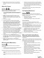
Carbon Monoxide (CO) Detectors
NOTICE: Installing functioning CO alarms indoors is the only
way to recognize CO gas. Common smoke alarms do not
detect CO gas and will not alert occupants of its presence.
A CO detector is an electronic device that detects hazardous
levels of CO. When a buildup of CO occurs, the detector will
alert the occupants by sounding an alarm and by flashing a
visual indicator light.
By law many states require a home to have a functioning
carbon monoxide (CO) detector.The installer must speak
with the owner aboutcarbon monoxide (CO) detectors.
Carbon monoxide detector(s) MUST be installed and
maintained indoors according to the manufacturer’s
instructions and recommendations. Smoke alarms cannot
detect carbon monoxide gas.
Contact the local building inspection division for any relevant
requirements regarding the use of CO detectors. See
National Fire Alarm and Signaling Code (NFPA) 72 Code and
Section R315 in the International Residential Code (ICC) for
additional details.
Potential Carbon Monoxide Entry Points
Operation Guidelines:
NOTICE: Operate this product only outdoors and in an area
that will not allow this deadly exhaust gas to collect.
Never operate this product inside homes, garages,
basements, crawl spaces, sheds, under a deck, or other
partially enclosed areas and understand that using fans and
opening doors in these areas may not provide adequate
ventilation. Carbon monoxide can quickly accumulate in these
forbidden spaces and can remain in the air for several hours
after this product has shut off.
Installation Guidelines:
Follow all instructions and illustrations in this manual when
placing an enclosure.
Always point the generator’s engine exhaust away from
occupied areas. Never expose your neighbors’ homes to the
engine exhaust flowing from your standby generator during
the installation process.
Never place the standby generator in any area where leaves
or debris can accumulate.
Generator exhaust can enter through windows, doors, and
other openings of a structure. Understand that exhaust and
CO can seep into a structure through the smallest openings.
7
Not for
Reproduction

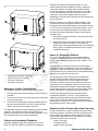
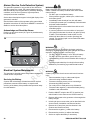
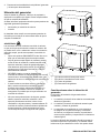
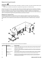
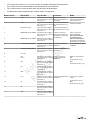
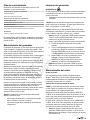
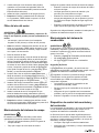
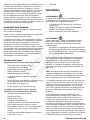
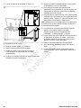
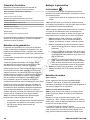
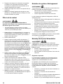
Protecting the Structure
Examine the structure to make sure that the sealing and caulking is sufficientenough to prevent air from leaking in or out.
Examine the structure for voids, cracks, or openings surrounding windows, doors, soffits, pipes, and vents, as these areas can
permit exhaust gas and Carbon Monoxide (CO) to enter the structure.
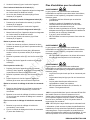
2
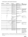
The table that follows includes examples of potential entry points for CO gas.
LOCATION ENTRY POINT EXPLANATION
A Windows and doors Openings that are part of a structure’s architecture can permit fresh air and CO into the structure, especially
when open.
B Garage door An open or improperly unsealed garage door can allow CO to flow into a garage.
C Attic vent Generator exhaust can enter through attic vents and the vents for soffits, crawl spaces, and ridges or roofs.
D Basement windows Basement windows or hatches that permit ventilation to or from the structure’s lower level also allow CO gas to
enter the structure.
E Furnace intake or exhaust
vent
Air intakes and furnace exhaust pipes are common entry points for CO gas.
F Wall cracks Any cracks in a structure’s walls, including the foundation and mortar, and any gaps around windows, doors,
and pipes can let CO in.
G Dryer vent Sometimes the exhaust vent for the clothes dryer lets CO gas into the structure.
H Airflow restrictions Areas featuring structural corners and heavy vegetation restrict the airflow and collect exhaust gas.
J Makeup air system Note: Keep all mechanical and gravity outdoor air intake openings for HVAC supply air systems 10 ft (3 m)
horizontally from the generator’s enclosure. Refer to section 401 in the ICC Mechanical Code for details on
requirements.
K Carbon monoxide
detector(s)
Note: Installing functioning CO alarms indoors is the only way to recognize CO gas. Common smoke alarms
do not detect CO gas and will not alert occupants of its presence.
8 BRIGGSandSTRATTON.COM
Not for
Reproduction

Reducing the Risk of Fire
WARNING
Exhaust heat/gases could ignite combustibles causing a fire, resulting in death or serious injury.
• Remove all combustible materials from in and around the generator compartment.
To help prevent fires, the generator must be installed a safe distance from all combustible materials. The unit’s engine,
alternator, and exhaust system components can become very hot during operation. Reduce the likelihood of a fire by keeping
the unit properly ventilated, properly maintained, free of fuel leaks, and away from combustible materials. Also, flammable
debris may collect within or outside the generator enclosure and may possibly ignite, causing a fire.
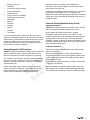
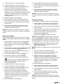
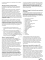
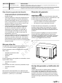
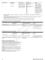
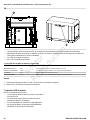
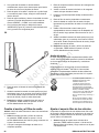
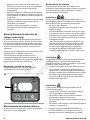
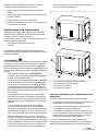
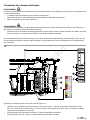
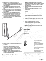
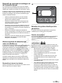
Distance Requirements
An owner must maintain minimum clearances around the generator enclosure. These clearances exist primarily for fire
prevention, but they also make sure that adequate space for maintenance tasks, such as removing the unit’s front, back,
exhaust outlet side, and air inlet side panels.
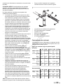
3
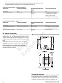
The table that follows explains the correct distances required for installation.
LOCATION ITEM EXPLANATION
A Front and end clearance Maintain a 3 ft (.91 m) minimum clearance from the front and ends of the generator. Keep shrubs, bushes,
plants, and trees this same minimum distance from the unit and never use vegetation to conceal the unit.
B Back clearance Since fuel and electrical connections occur here, keep 18 in (45.7 cm) minimum clearance per
independent testing laboratory, unless state codes tell you otherwise.
C Windows, vents, and openings Install the generator at least 5 ft (1.52 m) from all windows, doors, vents, window wells, or openings in the
wall. See Protecting the Structure section in this manual.
D Existing wall Keep the generator at least 18 in (45.7 cm) away from existing walls.
E Removable fence Keep removable fences at least 3 ft (.91 m) away from the front of the generator. Removable fences
include visual surrounds, fence panels, and temporary barriers without footings.
F Overhead clearance Maintain a 5 ft (1.52 m) minimum clearance from all structures, overhangs, projections on a wall, or trees.
G Maintenance and servicing
(not shown)
Allow adequate space to perform routine maintenance, such as servicing the engine and replacing the
battery. Never use shrubs, bushes, trees, or plants to conceal the generator.
9
Not for
Reproduction

Other General Location Guidelines
• Place the standby generator in a prepared location that
is flat and has provisions for water drainage.
• Install the standby generator in a location where sump
pump discharge, rain gutter down spouts, roof run-off,
landscape irrigation, or water sprinklers will not flood
the unit or spray the enclosure and enter any air inlet or
outlet openings.
• Install the standby generator where it will not affect or
obstruct any services (including covered, concealed and
underground), such as telephone, electric, fuel (natural
gas / LPG vapor), irrigation, air conditioning, cable,
septic, sewer, well and so forth.
• Install the standby generator where leaves, grass, snow,
etc will not obstruct air inlet and outlet openings. If
prevailing winds will cause blowing or drifting, you may
need to construct a windbreak to protect the unit.
Cold Weather Kits
If the generator operates in temperatures below 30 °F (-1 °C),
it is recommended that a Cold Weather Kit be installed.
Oil Sump Warmer Kit, Part Number 6840, includes:
• Oil sump warmer
• Install brackets
• Hardware
• Harness
Fuel Regulator Warmer Kit, Part Number 6845, includes:
• Regulator warmer
• Harness
Battery Warmer Kit, Part Number 6869, includes:
• Battery warmer
• Harness
These items are available at your local service dealer.
For more information, call 800-732-2989 between 8:00 AM
and 5:00 PM CT.
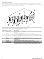
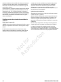
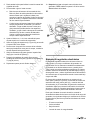
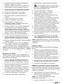
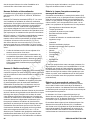
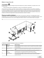
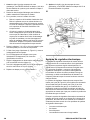
Lift the Generator
WARNING
Hazardous Voltage - Contact with power lines could cause
electric shock or burns, resulting in death or serious injury.
• If lifting or hoisting equipment is used, DO NOT contact
any power lines.
• DO NOT lift or move generator without assistance.
Correct tools, equipment, and qualified personnel must be
used in all phases of handling and moving the generator. The
approximate weight of the generator is listed in the Generator
Specifications section.
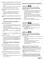
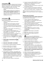
Use the lifting holes (A, Figure 4) in the base of the generator
to lift the generator onto the concrete slab or pad. Lift the
generator in accordance with the Occupational Safety and
Health Administration (OSHA) or local lifting regulations.
4
Anchor the Generator and Wind Ratings
Unless mandated by local or state codes, or required to
achieve wind rating, a concrete pad is not required for
anchoring the generator. For concrete pad mounting and
wind rating details, reference the Anchoring and Wind Rating
Diagram at the end of this manual.
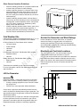
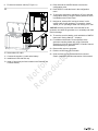
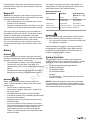
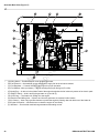
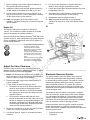
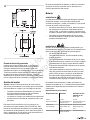
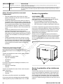
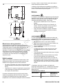
Electrical and Fuel Inlet Locations
The .75 in (19 mm) N.P.T. fuel inlet connector (A) and
electrical inlet locations (B) are shown inFigure 5.
A 1.73 in (44 mm) knock-out hole is provided for the electrical
inlet. Make sure that the installed conduit(s) enter the unit in
zone (C) as shown in the drawing below so that they properly
enter the electrical box and do not interfere with the fully
opened roof.
5
10 BRIGGSandSTRATTON.COM
Not for
Reproduction

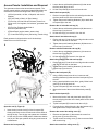
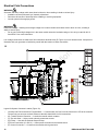
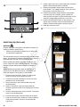
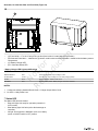
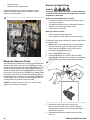
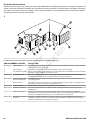
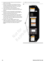
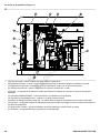
Access Panels:Installation and Removal
The generator enclosure has several access panels. The
access panels and the components located behind them are
referenced in the lists and images that follow (Figure 6):
• (A)Roof (controller, air filter, oil dipstick, and circuit
breaker)
• (B)Front Panel (oil drain, oil filter, battery)
• (C)End Cap,Air Inlet Side of Enclosure(control box
wiring cover, fuel regulator, fuel selector, generator data
label)
• (D)End Cap,Exhaust Outlet Side of
Enclosure(alternator fan)
• (E)Back Panel (engine starter, starter relay)
• (F)Control Box Wiring Cover (field wiring, control wiring)
Each generator is shipped with a set of identical keys
fastened to one of the end caps.
6
Open the roof (A, Figure 6):
1. Insert the key into the lock (G) of the front panel (B).
Gently push down on the roof above the lock to assist in
turning the key. Turn the key one-quarter turn clockwise.
2. Lift the roof (A) to the OPEN position.Make sure that the
roof (A) is in the open positionduring any panel removal
or attachment.
Remove the front panel (B):
1. Loosen the two self-retaining fasteners (H) that secure
the front panel (B) to the unit.
2. Lift the front panel (B) to remove it from the unit.
Attach the front panel (B):
1. Put the front panel (B) into the unit and align the tabs on
the frontpanel into the slots on the base.
2. Tighten the two self-retaining fasteners (H) to attach the
front panel (B) to the unit.
Remove theair inlet side end cap (C):
1. Loosen the two self-retaining fasteners (M)that secure
the endcap (C) to the unit.
2. Lift the end cap (C) to remove it from the unit.
Attachtheair inlet sideend cap(C):
1. Put the end cap (C) into the unit and align the tabs on the
end cap into the slots on the base.
2. Tighten the two self-retaining fasteners (M) that secure
the end cap (C) to the unit.
Removeexhaust outlet sideend cap (D):
1. Loosen the two self-retaining fasteners (J)that secure
the endcap (D) to the unit.
2. Lift the end cap (D)to remove it from the unit.
Attach theexhaust outlet sideend cap (D):
1. Put the end cap (D) into the unit and align the tabs on the
end cap into the slots on the base.
2. Tighten the two self-retaining fasteners (J) that secure
the end cap (D) to the unit.
Remove the back panel (E):
1. Using a Phillips head screw driver, loosen two self-
retaining fasteners (K) that secure the back panel (E) to
the unit.
2. Using a standard blade screw driver, gently lift the back
panel (E) lip off of the back rail.
3. Tip the back panel (E) back under the roof (A).
4. Move to the back of the unit and lift the back panel (E)
off.
Attach the back panel (E):
1. Move to the back of unit and place back panel (E) into
the unit, aligning the tabs on the back panel into the slots
on the base.
2. Tip the back panel (E) forward under the roof (A).
3. From the front or side of the unit, align the fasteners (K)
and tighten with a Phillips head screw driver.
Remove the control box wiring cover (F):
1. Remove two fasteners (L) that secure the control box
wiring cover (F) to the control box.
2. Tip the control box wiring cover (F) down to access field
and control wiring.
Attach the control box wiring cover (F):
11
Not for
Reproduction

1. Tip the control box wiring cover (F) up.
2. Attach the control box wiring cover (F) with the two
fasteners (L).
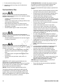
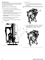
Fuel Installation Plan
WARNING
Propane and Natural Gas are extremely flammable and
explosive, which could cause burns, fire or explosion resulting
in death or serious injury.
• Installation must be performed by a licensed
professional.
• Install the fuel supply system according to NFPA 37 and
other applicable fuel-gas codes.
• Before placing the generator into service, the fuel
system lines must be properly purged and leak tested.
• NO leakage is permitted.
• DO NOT operate engine if smell of fuel is present.
WARNING
Propane and Natural Gas are extremely flammable and
explosive, which could cause burns, fire or explosion resulting
in death or serious injury.
• DO NOT operate the equipment if the fuel shut-off valve
is missing or inoperative.
WARNING
Propane and Natural Gas are extremely flammable and
explosive, which could cause burns, fire or explosion resulting
in death or serious injury.
• LP gas is heavier than air and will settle in low areas.
• Natural gas is lighter than air and will collect in high
areas.
• The slightest spark could ignite these fuels and cause
an explosion.
• DO NOT allow any open flame, spark, heat, or lit
cigarette.
NOTICE: DO NOT install the supplied flexible fuel line
underground or in contact with the ground.
Keep the entire flexible fuel line visible for periodic inspection.
Do not conceal it or run it within any wall, floor, or partition.
Never let the line contact these structures.
NOTICE: DO NOT bend the supplied flexible fuel line.
The following information addresses the planning phase
of installations for technicians specializing in gaseous fuel
systems. Always obey the local applicable fuel-gas codes
affecting the installation site. Consult your local fuel supplier
or fire marshal with any questions or problems.
TO THE INSTALLER: Consult with the generator owner(s)
and address any technical considerations affecting their
installation plans before applying these guidelines.
The general rules that follow apply to piping on gaseous fuel
systems:
• The piping material must follow federal and local codes,
with rigid mounting and protection against vibration.
• Protect piping from physical damage, especially where
it passes through flower and shrub beds and other
cultivated areas where damage can occur.
• Install the provided flexible fuel line(B, Figure
7)between the generator fuel inlet port (A) and the rigid
piping to prevent excessive stress on the piping material
due to thermal expansion and contraction.
• Provide a union (C) or flanged connection downstream
to allow for future removal.
• Install a manometer test port (D) for vapor fuels.
Use the port to install a manometer and check if the
engine receives the proper fuel pressure adequate for
operation. See the service center for a digital or analog
manometer designed for vapor fuels only (part number
19495). After completing the initial test runs, remove the
manometer and plug the port.
• For vapor fuels only: Protect piping from freezing in
areas that are prone to the formation of hydrates or ice.
When terminating hard piping, use a sediment trap (E)
where condensate liquid cannot likely freeze.
• Install a minimum of one accessible, approved manual
shut-off valve (F) in the fuel supply line within 6 ft (1.8
m) of the generator.
• Install a manual shut-off valve in the interior of the
building.
• Increase strength and flexibility of the piping supports
and connections in areas prone to earthquakes,
tornados, flood hazards, and unstable ground.
• Make sure that the size of the piping is adequate
enough to maintain the required supply pressures and
volume flow under varying generator load conditions,
with all gas appliances connected to the fuel system
turned on and operating.
• Use a pipe sealant or joint compound approved for use
with natural gas/liquefied petroleum on all threaded
fittings to reduce the possibility of leakage.
NOTICE: Keep thread sealant out of the gas piping to
prevent damage to component parts.
• Purge and leak-test piping according to applicable
codes and standards.
12 BRIGGSandSTRATTON.COM
Not for
Reproduction

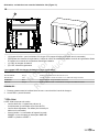
7
• (A)Generator Fuel Inlet
• (B)Flexible Fuel Line
• (C)Union Fitting
• (D)Manometer Test Port
• (E)Sediment Trap
• (F)Manual Shut-off Valve
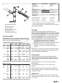
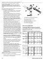
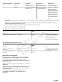
Fuel Consumption
Estimated fuel supply requirements at half and full load for
Liquified Petroleum Vapor (Propane) and Natural Gas (NG)
fuels are shown in the table that follows:
Liquified Petroleum Vapor Fuel (Propane)
17kW 18kW 20kW 22kW 26kW
Full
Load
ft3/hr
(m3/hr)
118
(3.4)
124 (3.6) 135
(3.9)
147
(4.3)
171
(4.9)
gal/hr (L/
hr)
3.3
(12.2)
3.5 (12.8) 3.7 (14) 4.1
(15.3)
4.70
(17.7)
BTU/
hr(MJ/
hr)
295,000
(312)
310,000
(327)
338,000
(356)
368,000
(388)
427,000
(450)
1/2 Load ft3/hr
(m3/hr)
74 (2.1) 77 (2.2) 83 (2.4) 87 (2.5) 94 (2.7)
gal/hr (L/
hr)
2.10
(7.7)
2.2 (8.0) 2.3
(8.6)
2.4 (9.0) 2.60
(9.7)
BTU/hr
(MJ/hr)
185,000
(196)
193,000
(204)
208,000
(219)
217,000
(229)
235,000
(248)
Natural Gas (NG)
17kW 18kW 20kW 22kW 26kW
Full
Load
ft3/
hr(m3/
hr)
248
(7.1)
252 (7.2) 260
(7.4)
281
(8.0)
323
(9.2)
BTU/
hr(MJ/
hr)
248,000
(262)
252,000
(267)
260,000
(275)
281,000
(297)
323,000
(341)
1/2 Load ft3/
hr(m3/
hr)
170
(4.9)
176 (5.1) 187
(5.3)
194
(5.5)
206
(5.9)
BTU/hr
(MJ/hr)
170,000
(180)
176,000
(186)
187,000
(198)
194,000
(205)
206,000
(218)
Physical
Properties
Natural Gas Propane (LP
Vapor)
Normal Atmospheric
State
Gas Gas
Boiling Point°F (°C) -259 (-167) -44 (-42)
Heating Value
BTU/gal (MJ/L)
liquid(Net LVH*)
63,310 (17.65) 83,340 (23.23)
BTU/gal (MJ/L)
liquid(gross**)
N/A 91,547 (25.52)
BTU/ft3 (MJ/m3) gas* 1,000 (37.26) 2,500 (93.15)
Density - ft3/gal (m3/L) 57.75 (0.43) 36.39 (0.27)
Weight -lb/gal (kg/L) 2.65 (0.32) 4.24 (0.51)
*LHV (Low Heat Value) is the more realistic rating.
**Gross heat value does not consider heat lost in the form of
water during combustion
Fuel Type
Consider the type of fuel that your generator uses, as it
affects the entire installation process. The system was factory
tested and adjusted using natural gas, but it can be converted
to use liquefied petroleum vapor. For correct engine function,
consider factors that affect each of these fuels, such as the
location and the duration of possible utility interruptions.
When choosing fuel type, obey these guidelines that follow:
• Use a clean, dry fuel that is free of moisture or
any particulate material. Using fuels outside the
recommended values can cause performance problems.
• In engines set up to run on propane (liquefied
petroleum), You must use commercial-grade HD-5
propane.
Natural gas or LP engines are certified to operate on natural
or liquid propane gas. The emissions control system for this
engine is EM (Engine Modifications).
Fuel Pressure
Bothliquefied petroleum (LP) and natural gas (NG) fuel
supply pressure at the generator’s fuel inlet port must be a
minimum value at full load with all gas appliances turned on
and in operation.
Natural Gas must be 3.5 to 7 in (89 to 178 mm) Water
Column (WC).
Liquefied Petroleum must be 11 to 14 in(279 to 356
mm)WC.
Make sure that all gas line shut-off valves are OPEN and
that adequate fuel pressure is available whenever automatic
operation is needed.
Power Loss
Engine power will decrease 3.5% for each 1,000 feet (300
meters) above sea level and 1% for each 10°F (5.6 °C) above
77 °F (25 °C).
13
Not for
Reproduction

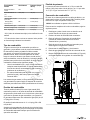
Fuel Conversion
The engine of your generator system is factory calibrated and
set to operate on natural gas (NG). It may also be operated
on liquefied petroleum (LP) vapor.
NOTICE: Units are set to NG at the factory.
To convert to either fuel, do the steps that follow:
1. Unlock and open the roof as described in the Access
Panels section of this manual.
2. Push the controller OFF button.
3. Remove the 15 amp fuse from the fuse holder (see fuse
location in the Features and Controls section).
4. Remove utility power to generator to de-energize the
battery charger.
5. Disconnect the negative (-) cable at the battery.
6. Remove theair inlet sideend cap.
7. Find the fuel selector valve (A, Figure 8) on top of the
fuel regulator (B).
8
8. Set Fuel Selector:
a. For LP, rotate the lever (C, Figure 9)on the fuel
selector valve until LP is aligned with “OUT” on the
fuel regulator.
9
b. For NG, rotate the lever clockwise 90° so the handle
position of the lever will be up and down and the
“NG” letters (D, Figure 10) will be on the left.
10
14 BRIGGSandSTRATTON.COM
Not for
Reproduction

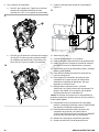
9. Find the fuel selector switch (E, Figure 11).
11
10. Select either LP or NG.
11. Connect the negative (-) cable at the battery.
12. Install the air inlet sideend cap.
13. Install 15 amp fuse(see fuse location in the Features and
Controls section).
14. Push and hold the CONFIG button to access the
configuration menu.
15. Push SELECT to edit the items in the configuration
menu.
16. To set up the generator’s controller for LP fuel, enter the
configuration menu by using the dealer password, which
is available on the Power Portal.
17. Navigate to “select profile” and push “select” on the
correct profile for the generator. For example, choose
“20KW_LP” for operating a 20kW unit running on LPfuel.
NOTICE: Selecting a profile that is not intended for the
generator can cause the generator to run erratically and could
result in damage.
18. To save the new fuel setting, push and hold the CONFIG
button until “Saving Settings…” displays.
19. For additional information on the operation of the
generator controller please refer to the "Operation
Instructions GC1030 Series GENSET Controller" manual
associated with your generator.
20. Restore utility power to generator.
21. Push the control board AUTO button.
22. Close and lock the roofas described in the Access
Panels: Installation and Removal section of this manual.
15
Not for
Reproduction

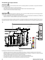
Electrical Field Connections
WARNING
Generator and utility voltage could cause electrical shock or burn resulting in death or serious injury.
• Installation must be performed by a licensed professional.
• Disconnect all sources of electricity before installing or servicing equipment.
• Ground system before applying power.
WARNING
Hazardous Voltage - Installing low and high voltage wire in same conduit could cause electric shock or burns, resulting in
death or serious injury.
• Do not run low and high voltage wire in the same conduit unless the insulation rating on ALL wiring is rated for 600 V.
See NFPA 70 for more information.
Low Voltage connections are made via a field connections terminal block (E, Figure 12) in main electrical area. Compare this
illustration with your generator to familiarize yourself with the location of these connections.
12
Legend for System Connector Location(Figure 12):
• (A)Utility and Field Connections Terminal Block — Connects utility 240 VAC from the fuse block in ATS to the controller.
Connect only one wire per terminal. Reference the table that follows for field connections.
• (B)Transfer Switch Connection — Controls the transfer switch contactor.
• (C)Two-wire Start — Helps provide optional remote start contact.
• (D)E-Stop — Use with the optional external E-Stop.
• (E)Power Connection (L1 and L2) — Offers power connection to the transfer switch.
• (F)Ground Connection — Connects to the transfer switch ground wire.
16 BRIGGSandSTRATTON.COM
Not for
Reproduction

• (G)Neutral Connection — Connects to the transfer switch neutral wire.
• (H)Communications Terminal Block — Reference the table that follows:
Pin Number Description Wire Type Connect To Notes
1 +12V # 18 AWG
[1mm2]conductors, 600 V
minimum, 90° C Cu wire
Transfer Switch Basic
Controller J7-8 12 VDC
2 GND # 18 AWG
[1mm2]conductors, 600 V
minimum, 90° C Cu wire
Transfer Switch Basic
Controller J7-7 GND
3 Xfer # 18 AWG
[1mm2]conductors, 600 V
minimum, 90° C Cu wire
Transfer Switch Basic
Controller J7-4 T/R
Transfer Switch Transfer
Signal (only works with Basic
Transfer Switch Controller)
4 2-WIRE START # 18 AWG
[1mm2]conductors, 600 V
minimum, 90° C Cu wire
5 2-WIRE START # 18 AWG
[1mm2]conductors, 600 V
minimum, 90° C Cu wire
Refer to the Transfer Switch
manual to verify if this function
is available
Contact Close for GENSET
Start. (Only for Transfer
Switch that provides this
option).
Mains monitoring must be
disabled in the controller
6 E-STOP # 18 AWG
[1mm2]conductors, 600 V
minimum, 90° C Cu wire
E-Stop Switch
7 E-STOP # 18
AWG[1mm2]conductors, 600
V minimum, 90° C Cu wire
E-Stop Switch
Contact Open to Shutdown
GENSET
8 Not Used - - -
9 VIN+
(+12V)
# 18
AWG[1mm2]conductors, 600
V minimum, 90° C Cu wire
Refer to the Amplify Gateway
manual
10 (D+) # 18 AWG[1mm2]
conductors, 600 V minimum,
90° C Cu wire
11 (D-) #18
AWG[1mm2]conductors,
600V minimum, 90° C Cu
wire
12 GND # 18 AWG
[1mm2]conductors, 600 V
minimum, 90° C Cu wire
Comm to WIFI module
Twisted pair #1: +12 V and
GND
Twisted pair #2: (D+) and (D-)
13 +12V # 18 AWG
[1mm2]conductors, 600 V
minimum, 90° C Cu wire
14 (A) # 18 AWG
[1mm2]conductors, 600 V
minimum, 90° C Cu wire
15 (B) # 18 AWG
[1mm2]conductors, 600 V
minimum, 90° C Cu wire
16 GND # 18 AWG
[1mm2]conductors, 600 V
minimum, 90° C Cu wire
Refer to the InfoHub™
Premium manual
Comm to Cellular Module
Twisted pair #1: +12 V and
GND
Twisted pair #2: (A) and (B)
25 UTILITY # 14 AWG [2.5mm2]600 V
minimum, 90° C Cu wire
Transfer Switch Utility
26 UTILITY # 14 AWG [2.5mm2]600 V
minimum, 90° C Cu wire
Transfer Switch Utility
Delivers power to the
generator’s battery charger,
controller, optional battery
warmer, optional oil warmer,
and optional fuel regulator
warmer. Also, when voltage
on these leads is lost in AUTO
Mode, generator will start if
Mains Monitoring is enabled
(default setting)
• For power output connection (L1, L2, Neutral (N), and Ground), refer to the National Electric Code (NEC) and local
codes.
• For communication wires use 600 V wire and # 18 AWG (1 mm2) twisted-pair conductors that do not exceed a length of
500 ft (150 m).
17
Not for
Reproduction

• When connecting to the terminal block, fasten only one wire to each connector screw.
• Torque terminal block screws to 4.4 in-lb [0.5 Newton meter (N·m)].
Connection Specifications: 17kW through 22kW
Connection Temperature Rating Recommended Wire Size
(AWG)
Torque Specifications
Circuit Breaker N/A N/A N/A
Field Connection Terminal 167°F(75°C) 2 to 14 CU
2 to 8 AL
2 to 3 AWG:50 in-lbs(5.64 Nm)
4 to 6 AWG: 45 in-lbs(5.08 Nm)
8 AWG:40 in-lbs(4.52 Nm)
10 to 14 AWG: 35 in-lbs(3.95 Nm)
Connection Specifications: 26kW
Connection Temperature Rating Recommended Wire Size
(AWG)
Torque Specifications
Circuit Breaker N/A N/A N/A
L1, L2, and N Terminal(copper or
aluminum)
140 °F/ 167 °F(60 °C/ 75 °C) 2/0 to 14 CU/AL 2/0 to 6 AWG: 120 in-lbs (13.56 Nm)
8 to 14 AWG: 40 in-lbs(4.52 Nm)
Ground Lug (copper or aluminum) 194 °F(90°C) 2 to 14 CU
2 to 8 AL
50 in-lbs(5.64 Nm)
AC System Connections
The generator uses a single-phase, three-wire AC connection
system(Figure 13). The stator assembly consists of a pair
of stationary windings with two leads appearing from each
winding. The junction of leads 22 and 33 forms the neutral
lead.
NOTICE: Neutral is not bonded to ground at generator.
NOTICE: The generator must be used with an UL listed
transfer switch that is compatible with the generator.
Only use the generator with a listed transfer switch that is
compatible with the generator.
13
Ground the Generator
Unless mandated by local code, additional chassis grounding
to earth at the generator is not required. Any grounding at
the generator must use paint-piercing lock washers (or their
equivalent). Any listed terminals must be installed per the
18 BRIGGSandSTRATTON.COM
Not for
Reproduction

terminal supplier’s instructions. All grounding and terminal
installations must comply with national electrical codes and
local requirements.
Engine Oil
NOTICE: Any attempt to crank or start the engine before it
has been correctly filled with the recommended oil will result
in equipment failure and service codes.
• Refer to Maintenance in the Operation section of this
manual for oil fill information.
• Damage to equipment resulting from failure to obey this
instruction will void the engine and generator warranty.
This engine ships from the factory pre-run and filled with
full synthetic oil (API SJ/CF 5W-30). This allows for system
operation in a wide range of temperature and climate
conditions. Before starting the engine, check the oil level as
described in the Maintenance section of this manual.
The use of full synthetic oil does not alter the required oil
change intervals described in the Operation section of this
manual.
Battery
WARNING
Storage batteries give off explosive hydrogen gas during
recharging. Slightest spark could ignite hydrogen and cause
explosion, resulting in death or serious injury.
• DO NOT dispose of battery in a fire. Recycle battery.
• DO NOT allow any open flame, spark, heat, or lit
cigarette during and for several minutes after charging a
battery.
• Discharge static electricity from body before touching
batteries by first touching a grounded metal surface.
WARNING
Battery electrolyte fluid contains acid and is extremely
caustic. Contact with battery contents could cause severe
chemical burns.
• DO NOT open or mutilate the battery.
• Wear protective goggles, rubber apron, rubber boots
and rubber gloves.
• Immediately wash electrolyte from skin with water.
• If electrolyte contacts eyes, immediately flush with water
and seek medical attention.
• Spilled electrolyte is to be washed down with an acid
neutralizing agent.
• A common practice is to use a solution of one pound
(500 grams) bicarbonate of soda to one gallon (4 liters)
of water. The bicarbonate of soda solution is to be
added until the evidence of reaction (foaming) has
ceased. The resulting liquid is to be flushed with water
and the area dried.
The installer must supply and install a rechargeable 12 V
starting battery. The starting battery MUST conform to the
specifications shown in the chart that follows.
Battery Specifications
Specifications Standard Cold Start (Less
than 30 °F / -1 °C)
Volts 12 VDC 12 VDC
Amps (Minimum) 540 CCA (Cold
Cranking Amps)
800 CCA(Cold
Cranking Amps)
Construction Wet Lead Acid Wet Lead Acid
Terminal Type Top Post Type Battery Top Post Type Battery
Dimensions (Maximum) BCI Size 26 or BCI Size
51
BCI Size 24
WARNING
With the battery connected, the generator could crank and
start without warning resulting in death or serious injury.
• Do not connect the negative (-) cable at the battery until
the installation is complete.
Install the battery as described in Servicing the Battery in
the Maintenance section of this manual. Make sure that
the NEGATIVE cable is connected last and that the red
POSITIVE terminal insulator is secure.
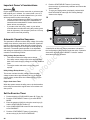
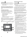
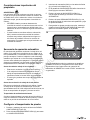
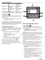
System Controller
The generator's controller, located inside the generator
housing, is shown in the image that follows (Figure 14).Brief
descriptions of the controls used during installation are:
• (A)Menu/Programming Navigation Buttons
• (B)Stop/Config Button
• (C)Start/Select Button
• (D)Auto/Manual Button
• (E)Alarm
• (F)Digital Display — Displays generator mode, menu
options, and alarms
NOTICE: Detailed descriptions of the controls are located
in the Description of Control Keys section insidethe online
"Operation Instructions GC1030 Series GENSET Controller"
manual associated with your generator.
19
Not for
Reproduction

14
Initial Start-Up (No Load)
WARNING
Exhaust heat/gases could ignite combustibles causing a fire,
resulting in death or serious injury.
• Remove all combustible materials from in and around
the generator compartment.
The unit has been set up for natural gas (NG) operation at the
factory.Fuel conversion must be completed prior to doing the
steps that follow.See the Fuel Conversion section.
Before operating the standby generator or putting it into
service, inspect the entire installation carefully. Then begin
testing the system without electrical loads connected, as
follows:
NOTICE: When the generator starts for thefirst time, it
purges air from the gaseous fuel lines. This process can
cause the engine to run roughly for a few minutes.
1. Remove the two screws(A, Figure 15)retaining the
control box wiring cover. Remove the cover.
2. Connect an accurate multimeter to the line side of the
generator’s main circuit breaker.
3. Set the generator’s main circuit breaker to the ON
(closed) position.
4. Install a 15 amp fuse in the fuse holder below the
controller(see fuse location in the Features and Controls
section).
5. Push the start/select button on the controller. The engine
starts in Low Idle Mode (LIM).
6. Push the button again to bring the engine to full speed.
7. Listen for unusual noises, vibrations, or other indications
of abnormal operation. Check for oil leaks while the
engine runs.
8. Let the engine warm up for approximately five minutes to
allow the internal temperatures to stabilize.
9. Examine the generator output at the load side of the
circuit breaker. The voltage should be 225 to 250 V and
the frequency should be 59 to 61 Hz.
10. Examine the generator output between one generator
connection lug and a neutral lug, then between the
other generator connection lug and a neutral lug. In both
cases, the voltage reading should be 112 to 125 V.
11. Push the STOP/CONFIG button on the controller. The
engine enters cool-down mode for approximately five
minutes. Push the button again to stop the engine.
12. Install the control box cover.
15
20 BRIGGSandSTRATTON.COM
Not for
Reproduction
La page est en cours de chargement...
La page est en cours de chargement...
La page est en cours de chargement...
La page est en cours de chargement...
La page est en cours de chargement...
La page est en cours de chargement...
La page est en cours de chargement...
La page est en cours de chargement...
La page est en cours de chargement...
La page est en cours de chargement...
La page est en cours de chargement...
La page est en cours de chargement...
La page est en cours de chargement...
La page est en cours de chargement...
La page est en cours de chargement...
La page est en cours de chargement...
La page est en cours de chargement...
La page est en cours de chargement...
La page est en cours de chargement...
La page est en cours de chargement...
La page est en cours de chargement...
La page est en cours de chargement...
La page est en cours de chargement...
La page est en cours de chargement...
La page est en cours de chargement...
La page est en cours de chargement...
La page est en cours de chargement...
La page est en cours de chargement...
La page est en cours de chargement...
La page est en cours de chargement...
La page est en cours de chargement...
La page est en cours de chargement...
La page est en cours de chargement...
La page est en cours de chargement...
La page est en cours de chargement...
La page est en cours de chargement...
La page est en cours de chargement...
La page est en cours de chargement...
La page est en cours de chargement...
La page est en cours de chargement...
La page est en cours de chargement...
La page est en cours de chargement...
La page est en cours de chargement...
La page est en cours de chargement...
La page est en cours de chargement...
La page est en cours de chargement...
La page est en cours de chargement...
La page est en cours de chargement...
La page est en cours de chargement...
La page est en cours de chargement...
La page est en cours de chargement...
La page est en cours de chargement...
La page est en cours de chargement...
La page est en cours de chargement...
La page est en cours de chargement...
La page est en cours de chargement...
La page est en cours de chargement...
La page est en cours de chargement...
La page est en cours de chargement...
La page est en cours de chargement...
La page est en cours de chargement...
La page est en cours de chargement...
La page est en cours de chargement...
La page est en cours de chargement...
La page est en cours de chargement...
La page est en cours de chargement...
La page est en cours de chargement...
La page est en cours de chargement...
La page est en cours de chargement...
La page est en cours de chargement...
La page est en cours de chargement...
La page est en cours de chargement...
La page est en cours de chargement...
La page est en cours de chargement...
La page est en cours de chargement...
La page est en cours de chargement...
La page est en cours de chargement...
La page est en cours de chargement...
La page est en cours de chargement...
La page est en cours de chargement...
La page est en cours de chargement...
La page est en cours de chargement...
La page est en cours de chargement...
La page est en cours de chargement...
La page est en cours de chargement...
La page est en cours de chargement...
La page est en cours de chargement...
La page est en cours de chargement...
La page est en cours de chargement...
La page est en cours de chargement...
La page est en cours de chargement...
La page est en cours de chargement...
La page est en cours de chargement...
La page est en cours de chargement...
La page est en cours de chargement...
La page est en cours de chargement...
La page est en cours de chargement...
La page est en cours de chargement...
La page est en cours de chargement...
La page est en cours de chargement...
-
 1
1
-
 2
2
-
 3
3
-
 4
4
-
 5
5
-
 6
6
-
 7
7
-
 8
8
-
 9
9
-
 10
10
-
 11
11
-
 12
12
-
 13
13
-
 14
14
-
 15
15
-
 16
16
-
 17
17
-
 18
18
-
 19
19
-
 20
20
-
 21
21
-
 22
22
-
 23
23
-
 24
24
-
 25
25
-
 26
26
-
 27
27
-
 28
28
-
 29
29
-
 30
30
-
 31
31
-
 32
32
-
 33
33
-
 34
34
-
 35
35
-
 36
36
-
 37
37
-
 38
38
-
 39
39
-
 40
40
-
 41
41
-
 42
42
-
 43
43
-
 44
44
-
 45
45
-
 46
46
-
 47
47
-
 48
48
-
 49
49
-
 50
50
-
 51
51
-
 52
52
-
 53
53
-
 54
54
-
 55
55
-
 56
56
-
 57
57
-
 58
58
-
 59
59
-
 60
60
-
 61
61
-
 62
62
-
 63
63
-
 64
64
-
 65
65
-
 66
66
-
 67
67
-
 68
68
-
 69
69
-
 70
70
-
 71
71
-
 72
72
-
 73
73
-
 74
74
-
 75
75
-
 76
76
-
 77
77
-
 78
78
-
 79
79
-
 80
80
-
 81
81
-
 82
82
-
 83
83
-
 84
84
-
 85
85
-
 86
86
-
 87
87
-
 88
88
-
 89
89
-
 90
90
-
 91
91
-
 92
92
-
 93
93
-
 94
94
-
 95
95
-
 96
96
-
 97
97
-
 98
98
-
 99
99
-
 100
100
-
 101
101
-
 102
102
-
 103
103
-
 104
104
-
 105
105
-
 106
106
-
 107
107
-
 108
108
-
 109
109
-
 110
110
-
 111
111
-
 112
112
-
 113
113
-
 114
114
-
 115
115
-
 116
116
-
 117
117
-
 118
118
-
 119
119
-
 120
120


Simplicity MANUAL, OPERATOR'S AND INSTALLATION Manuel utilisateur
- Catégorie
- Groupes électrogènes
- Taper
- Manuel utilisateur
dans d''autres langues
Documents connexes
-
Simplicity 080084 Manuel utilisateur
-
-
Simplicity 076030-0 Guide d'installation
-
-
-
-
-
