L-Acoustics 8XT Manuel utilisateur
- Catégorie
- Haut-parleurs
- Taper
- Manuel utilisateur


8XT_UM_ML_1-3
w w w . l - a c o u s t i c s . c o m
1
11
1 en
EN
1
11
1 SAFETY WARNINGS
SAFETY WARNINGSSAFETY WARNINGS
SAFETY WARNINGS
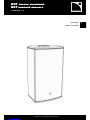
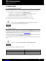
All information hereafter detailed applies for the L-ACOUSTICS® 8XT Coaxial Enclosure, designated in this section
as ‘‘the product’’.
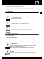
1.1 Symbol description
Throughout this manual the potential risks are indicated by the following symbols:
The WARNING symbol indicates a potential risk of physical harm to the user or people within close
proximity to the product.
In addition, the product may also be damaged.
The CAUTION symbol notifies the user about information to prevent possible product damage.
The IMPORTANT symbol is a notification of an important recommendation of use.
1.2 Important safety instructions
1. Read this manual
2. Heed all safety warnings
3. Follow all instructions
4. The user should never incorporate equipment or accessories not approved by L-ACOUSTICS®
5. Sound Levels
Sound systems are capable of producing high Sound Pressure Levels which can be dangerous and
potentially cause hearing damage especially when exposed to them over a long period of time.
Do not stay within close proximity of the loudspeakers when operating.
6. Heat
Do not operate the product near any heat source, such as radiators or other devices.
!
WARNING
!
IMPORTANT
!
CAUTION
!
WARNING
!
CAUTION

8
88
8XT
XTXT
XT
C
CC
COAXIAL ENCLOSURE
OAXIAL ENCLOSUREOAXIAL ENCLOSURE
OAXIAL ENCLOSURE
user manual
user manualuser manual
user manual
VERSION 1.3
8XT_UM_ML_1-3
w w w . l - a c o u s t i c s . c o m
2
22
2 en
7. Water and moisture
Even if the product is weather-resistant, it can not be exposed to moisture (rain, sea spray, shower,
steam) for a long period of time, nor put in direct contact or partially immersed in water. This would
cause irreversible damage to exposed components.
8. System Parts and Rigging inspection
All system components must be inspected before use, in order to detect any possible defects.
Please refer to the “Care and Maintenance” section of this manual as well as any other manuals
pertaining to the system for a detailed description of the inspection procedure.
Any part showing any sign of defect must immediately be put aside and withdrawn from use to be
inspected by qualified service personnel.
9. Mounting instructions
Do not place the product on an unstable cart, stand, tripod, bracket, or table. The product may fall
and be seriously damaged, and may cause serious human injury.
Any mounting of the product should follow the manufacturer’s instructions given in this manual,
and should use a mounting accessory recommended by the manufacturer.
10. Conditions which require immediate service
Servicing is required when the product has been damaged in any way such as:
•
••
• The product has been exposed to rain or moisture,
• The product was dropped or the enclosure is damaged,
• The product does not operate normally.
11. Manual
Keep this manual in a safe place during the product lifetime. This manual forms an integral part of the
product. Reselling of the product is only possible if the user manual is available. Any changes made to
the product have to be documented in writing and passed on to the buyer in the event of resale.
!
IMPORTANT
!
WARNING
!
WARNING
!
CAUTION
!
CAUTION

8XT_UM_ML_1-3
w w w . l - a c o u s t i c s . c o m
3
33
3 en
EN
1.3 EC declaration of conformity
L-ACOUSTICS®
13 rue Levacher Cintrat
Parc de la Fontaine de Jouvence
91462 Marcoussis Cedex
France
States that the following product:
Loudspeaker enclosure, 8XT
Is in conformity with the provisions of:
Machinery Directive 2006/42/EC
Low Voltage Directive 2006/95/EC
Applied rules and standards:
EN ISO 12100-1: 2004 (Mechanical Safety)
EN60065 (Electrical Safety)
Established at Marcoussis, France
November 9th, 2009
Christophe Pignon

8
88
8XT
XTXT
XT
C
CC
COAXIAL ENCLOSURE
OAXIAL ENCLOSUREOAXIAL ENCLOSURE
OAXIAL ENCLOSURE
user manual
user manualuser manual
user manual
VERSION 1.3
8XT_UM_ML_1-3
w w w . l - a c o u s t i c s . c o m
4
44
4 en
2
22
2 CONTENTS
CONTENTSCONTENTS
CONTENTS
1
SAFETY WARNINGS 1
1.1
Symbol description ............................................................................................................................................1
1.2
Important safety instructions..............................................................................................................................1
1.3
EC declaration of conformity .............................................................................................................................3
2
CONTENTS 4
3
INTRODUCTION 5
3.1
Welcome to L-ACOUSTICS®............................................................................................................................5
3.2
Unpacking .........................................................................................................................................................5
4
XT COAXIAL RANGE 6
5
8XT COAXIAL ENCLOSURE 9
6
INSTALLATION 10
6.1
Flying or stacking the 8XT ...............................................................................................................................10
6.2
Connecting speakers .......................................................................................................................................10
7
OPERATION 12
7.1
System configuration........................................................................................................................................12
7.2
“FULL RANGE” mode.....................................................................................................................................12
7.2.1
Description.......................................................................................................................................12
7.2.2
Connecting the 8XT to the LA4........................................................................................................12
7.2.3
[8XT_FR], [8XT_FI], and [8XT_MO] presets ...................................................................................13
7.3
“HIGH-PASS” mode........................................................................................................................................14
7.3.1
Description.......................................................................................................................................14
7.3.2
Connecting the 8XT to the LA4........................................................................................................14
7.3.3
[8XT_FR_100], [8XT_FI_100], and [8XT_MO_100] presets.............................................................14
7.4
“HYBRID’’ mode.............................................................................................................................................15
7.4.1
Description.......................................................................................................................................15
7.4.2
Connecting the 8XT and SB118 to the LA4.......................................................................................15
7.4.3
[8XT_SB118] preset.........................................................................................................................16
8
CARE AND MAINTENANCE 17
8.1
Maintenance information .................................................................................................................................17
8.2
Testing procedure...........................................................................................................................................17
8.2.1
Check of transducer and enclosure acoustic behavior........................................................................17
8.2.2
Check of mechanical assembly and rigging parts................................................................................17
8.2.3
Check of external aspect ..................................................................................................................17
8.3
Transducer service ..........................................................................................................................................18
8.3.1
LF loudspeaker.................................................................................................................................18
8.3.2
HF driver or diaphragm ....................................................................................................................18
8.4
Spare parts and recommended tools................................................................................................................19
9
SPECIFICATIONS 20

8XT_UM_ML_1-3
w w w . l - a c o u s t i c s . c o m
5
55
5 en
EN
3
33
3 INTRODUCTION
INTRODUCTIONINTRODUCTION
INTRODUCTION
3.1 Welcome to L-ACOUSTICS®
Thank you for purchasing the L-ACOUSTICS® 8XT Coaxial Enclosure.
This manual contains essential information on installing and operating the product correctly and safely. It is necessary to
read this manual carefully in order to become familiar with these procedures.
As part of a continuous evolution of techniques and standards, L-ACOUSTICS® reserves the right to
change the specifications of the product and the content of this manual without prior notice. Please check
the L-ACOUSTICS® web site at www.l-acoustics.com on a regular basis for latest updates.
Should the product requires repair or if information about the warranty is needed, please contact an approved
L-ACOUSTICS® distributor. The address of the nearest distributor is available on the L-ACOUSTICS® web site.
3.2 Unpacking
Carefully open the shipping carton and check the product for any noticeable damage. Each L-ACOUSTICS® product is
tested and inspected before leaving the factory and should arrive in perfect condition.
If found to be damaged, notify the shipping company or the distributor immediately. Only the consignee may initiate a
claim with the carrier for damage incurred during shipping. Be sure to save the carton and packing materials for the
carrier's inspection.

8
88
8XT
XTXT
XT
C
CC
COAXIAL ENCLOSURE
OAXIAL ENCLOSUREOAXIAL ENCLOSURE
OAXIAL ENCLOSURE
user manual
user manualuser manual
user manual
VERSION 1.3
8XT_UM_ML_1-3
w w w . l - a c o u s t i c s . c o m
6
66
6 en
4
44
4 XT COAXIAL RANGE
XT COAXIAL RANGEXT COAXIAL RANGE
XT COAXIAL RANGE
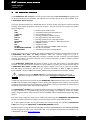
The L-ACOUSTICS® 8XT enclosure is the most compact model within the XT Coaxial Range and operates over
the 65 Hz to 20 kHz frequency bandwidth. This response can be extended down to 32 Hz with the addition of the
L-ACOUSTICS® SB118 subwoofer.
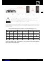
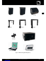
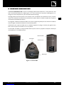
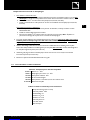
The system approach developed by L-ACOUSTICS® for the XT range consists of the elements needed to fully take
advantage of the possible configurations and optimize the system. The main components of the system are (see also
Figure 1and Figure 2):
8XT Passive compact coaxial enclosure
12XT Active/passive multipurpose coaxial enclosure
115XT HiQ Active coaxial stage monitor
ETR8-2 Mounting accessory for the 8XT enclosure
ETR12-2 Mounting accessory for the 12XT enclosure
ETR15 Mounting accessory for the 115XT HiQ enclosure
XTLIFTBAR Rigging accessory for the 12XT and 115XT HiQ enclosures
SB118 Subwoofer enclosure
LA4 Amplified controller
LA-RAK Touring rack containing three LA8 amplified controllers
LA NETWORK MANAGER Remote control software
SOUNDVISION Acoustical and mechanical modeling software
The XT range components are compatible with standard L-ACOUSTICS® accessories. These accessories include the
L-ACOUSTICS® SP.7, SP10, and SP25 loudspeaker cables with respective lengths of 0.7 m/2 ft,
10 m/30 ft, and 25 m/80 ft. These cables allow connection of the 8XT and 12XT enclosures to the LA4 amplified
controller. Each cable is a 4-conductor cable with 4 mm2 conductor cross-section (13 SWG, 11 AWG) and features
4-point Speakon® connectors.
The L-ACOUSTICS® DOFILL-LA8 cable allows connection of the 115XT HiQ enclosure to the LA8 amplified
controller. This cable features 8-point PA-COM® and 4-point Speakon® connectors and must be extended using the
L-ACOUSTICS® DO.7, DO10, or DO25 cables with respective lengths of 0.7 m/2 ft, 10 m/30 ft, and 25 m/80 ft.
Each DO cable is an 8-conductor cable with 4 mm2 conductor cross-section (13 SWG, 11 AWG) and features
8-point PA-COM® connectors. Note: The PA-COM® standard is fully compatible with the CA-COM® standard.
ALWAYS connect the new DOFILL-LA8 cable on the LA8 amplified controller for active 2-way
applications, as using the old DOFILL cable may result in damaging the loudspeaker components.
The 8XT and 12XT are driven and powered by the L-ACOUSTICS® LA4 amplified controller and the 115XT HiQ by
the LA8. These controllers ensure intelligent protection, filtering, and equalization of the enclosures. Four channels of
amplification are provided along with the OEM factory preset libraries, ensuring the optimization and performance of
the systems within the limits of the recommended configurations.
The L-ACOUSTICS® LA-RAK touring rack offers an advanced solution for all L-ACOUSTICS® systems covering signal
and power distribution in a comprehensive plug and play touring package. The LA-RAK was created as a universal
platform designed to facilitate cross-rental and to ensure compatibility with the L-ACOUSTICS® legacy analog cabling
standard.
Each system design configuration should first be modeled and studied using the L-ACOUSTICS® SOUNDVISION
software. The software predictions are based on the preset parameters stored in the amplified controllers.
Up to 253 amplified controllers can be interconnected and monitored through the proprietary L-ACOUSTICS®
L-NET network using the L-ACOUSTICS® LA NETWORK MANAGER software.
Detailed description on using the LA4 and LA8 amplified controllers, SOUNDVISION and LA NETWORK MANAGER
software is beyond the scope of this manual. Please refer to the appropriate documentation, also available on the
L-ACOUSTICS® web site at www.l-acoustics.com.
!
CAUTION


8
88
8XT
XTXT
XT
C
CC
COAXIAL ENCLOSURE
OAXIAL ENCLOSUREOAXIAL ENCLOSURE
OAXIAL ENCLOSURE
user manual
user manualuser manual
user manual
VERSION 1.3
8XT_UM_ML_1-3
w w w . l - a c o u s t i c s . c o m
8
88
8 en
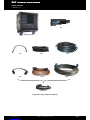
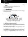
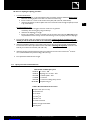
Figure 2: XT range components (part 2)
DO25
DO10
DO.7
DOFILL
-
LA8
+
LA4
LA
-
RAK with
3 LA8
SP25
SP10
SP.7

8XT_UM_ML_1-3
w w w . l - a c o u s t i c s . c o m
9
99
9 en
EN
5
55
5 8XT COAXIAL ENCLOSURE
8XT COAXIAL ENCLOSURE8XT COAXIAL ENCLOSURE
8XT COAXIAL ENCLOSURE
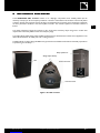
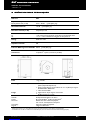
The L-ACOUSTICS® 8XT enclosure contains a 1.5’’ diaphragm compression driver coaxially loaded (for HF
directivity control) by an 8’’ low frequency transducer mounted in a bass-reflex tuned enclosure. The internal passive
crossover network uses proprietary third order filters. The linearization and protection of the transducers is defined by
the drive parameters contained in the LA4 amplified controller. The nominal impedance of the 8XT enclosure is
8 ohms.
The coaxial transducer arrangement produces a 100° axi-symmetric directivity output along with a smooth tonal
response free of secondary lobes over the entire frequency range.
The wedge-shaped cabinet design makes the 8XT perfectly suited to all stacked sound reinforcement applications. The
cabinet can also be flown as well as pole, wall, or ceiling-mounted.
The 8XT cabinet is made of high grade Baltic birch plywood with remarkable mechanical and acoustical properties for
improved long term durability.
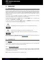
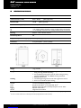
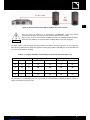
Figure 3: The 8XT enclosure
4 inserts with screws
Grill
Pole mount socket
Wedge
-
shaped cabinetry
Safety eyebolt insert

8
88
8XT
XTXT
XT
C
CC
COAXIAL ENCLOSURE
OAXIAL ENCLOSUREOAXIAL ENCLOSURE
OAXIAL ENCLOSURE
user manual
user manualuser manual
user manual
VERSION 1.3
8XT_UM_ML_1-3
w w w . l - a c o u s t i c s . c o m
10
1010
10 en
6
66
6 INSTALLATION
INSTALLATIONINSTALLATION
INSTALLATION
6.1 Flying or stacking the 8XT
The integrated rigging components and the wedge-shaped cabinet design of the 8XT enclosure (Figure 3) allow various
setups such as:
•
••
• Wall or ceiling-mounting using the L-ACOUSTICS® ETR8-2 mounting accessory.*
•
••
• Wall or ceiling-mounting using the OMNIMOUNT® 30.0 SERIES mounting accessories (four M6 inserts).*
•
••
• Mounting to a 35 mm/1.4 inch pole stand using the integrated pole socket.
•
••
• Stacking with two fixed angle settings of 30° and 40° with regard to the vertical.
* A safety eyebolt accessory can be added using the M8 insert located on the rear face of the 8XT enclosure.
Note: The “M6” and “M8” notations refer to the European standard (see applicable external documentation).
Refer to the “XT and P’’ rigging procedures manual to get acquainted with the XT range
specific procedures.
6.2 Connecting speakers
The 8XT enclosure is driven and powered by the dedicated L-ACOUSTICS® LA4 amplified controller. Each LA4 amp
channel can drive one or two (in parallel) 8XT enclosures. For more details please refer to the “LA4’’ user manual
also available on the L-ACOUSTICS® web site at www.l-acoustics.com.
The 8XT enclosure is equipped with two 4-point Speakon® connectors wired in parallel, allowing connection with a
second 8XT enclosure in parallel using one of the L-ACOUSTICS® SP.7, SP10, or SP25 cables.
The same cables are recommended to connect the 8XT enclosure to the LA4 amplified controller (see Figure 2 and
Figure 4).
A maximum of two 8XT enclosures can be connected per LA4 output channel.
The L-ACOUSTICS® wiring convention is as follows:
Speakon® connector labels Connection to transducers
1+ IN +
1- IN -
2+ Not used
2- Not used
!
CAUTION
!
WARNING

8XT_UM_ML_1-3
w w w . l - a c o u s t i c s . c o m
11
1111
11 en
EN
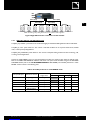
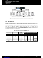
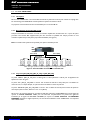
Figure 4: Connecting two 8XT in parallel to the LA4 amp channel #1
To ensure both high performance and safety, L-ACOUSTICS® recommends the exclusive use of
high-quality, fully insulated speaker cables made of stranded copper wire.
In order to preserve a high damping factor it is desirable to keep loudspeaker cables as short as
possible and with a gauge offering low resistance per unit length.
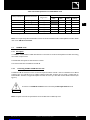
The following table provides information regarding the recommended length versus wire cross-section. Two cases are
possible depending on the impedance load connected to the LA4 (8 Ω for a single 8XT enclosure, 4 Ω for two 8XT
enclosures in parallel):
Table 1: Maximum cable length versus conductor cross-section for Damping Factor > 20
Cross-section Length for one 8XT (8 Ω load) Length for two 8XT (4 Ω load)
mm2 SWG AWG m ft m ft
2.5 15 13 30 100 15 50
4 13 11 50 160 25 80
6 11 9 74 240 37 120
10 9 7 120 390 60 195
According to the calculation in Table 1, one SP25 cable (4 mm², 25 m) can be used to power two 8XT in parallel (4 Ω
load) with a damping factor still greater than 20.
SP.7, SP10, or SP25
SP.7,
SP10,
or SP25
!
IMPORTANT

8
88
8XT
XTXT
XT
C
CC
COAXIAL ENCLOSURE
OAXIAL ENCLOSUREOAXIAL ENCLOSURE
OAXIAL ENCLOSURE
user manual
user manualuser manual
user manual
VERSION 1.3
8XT_UM_ML_1-3
w w w . l - a c o u s t i c s . c o m
12
1212
12 en
7
77
7 OPERATION
OPERATIONOPERATION
OPERATION
7.1 System configuration
The choice of a system configuration should be the result of an electro-acoustic study conducted by an expert (System
Engineer or Audio Consultant). However, this will not be discussed here as sound-design aspects are beyond the scope
of this manual. This study can rely on the simulations modeled in SOUNDVISION software, yielding electro-acoustic
predictions which take into account the enclosures’ manufacturer data and particular situational usage, as well as the
projected environment.
Three operation modes (“FULL RANGE”, “HIGH-PASS”, and “HYBRID”), each one associated with a set of factory
presets, will allow building all the common configurations (C, LR, LCR, distributed…).
The 8XT enclosures can be used as a standalone system in the “FULL RANGE’’ mode or in combination with
subwoofers in the “HIGH-PASS’’ and “HYBRID’’ modes.
For each mode a distinction is drawn between ‘‘FRONT’’, ‘‘FILL’’, and ‘‘MONITOR’’ presets as they respectively
match front-of-house, distributed, and half-space loading applications.
The MONITOR presets have been optimized from the 1.3 to the 2.0 preset library versions.
The LA4 output channel assignment varies with the preset selected by the user.
ALWAYS check that the 8XT enclosures are connected to correct LA4 output channels before
operating.
Note: The latest version of the preset library can be supplied by an L-ACOUSTICS® authorized representative and is
also downloadable from the L-ACOUSTICS® web site at www.l-acoustics.com.
7.2 “FULL RANGE” mode
7.2.1 Description
In ‘‘FULL RANGE’’ mode the 8XT enclosures are used in standalone configurations within their nominal bandwidth
(65 Hz – 20 kHz), for applications not requiring low frequency extension.
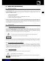
7.2.2 Connecting the 8XT to the LA4
Each 8XT enclosure must be connected to an LA4 output channel ranging from channel 1 through 4. An additional 8XT
enclosure can be connected in parallel with each of the first ones. Therefore a single LA4 amplified controller can drive
up to eight 8XT enclosures (see Figure 5).
Note: The system resources are optimized for four or eight 8XT per LA4.
!
IMPORTANT
!
CAUTION

8XT_UM_ML_1-3
w w w . l - a c o u s t i c s . c o m
13
1313
13 en
EN
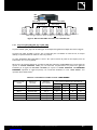
Figure 5: Eight 8XT enclosures connected to an LA4 controller
7.2.3 [8XT_FR], [8XT_FI], and [8XT_MO] presets
The [8XT_FR] ‘‘FRONT’’ preset features LF and HF shelving EQ for standalone FOH applications without subwoofers.
The [8XT_FI] ‘‘FILL’’ preset results in a ‘‘flat’’ contour in free field conditions for use in speech reinforcement, classical
music, or close proximity fill applications.
The [8XT_MO] ‘‘MONITOR’’ preset results in a ‘‘flat’’ contour in half-space loading conditions for floor monitoring, wall,
or ceiling-mounted applications.
Activate the LOAD PRESET menu from the LA4 amplified controller front panel and then select the desired preset.
Refer to the ‘‘LA4’’ user manual for additional instructions. The preset is also accessible using the LA NETWORK
MANAGER software (refer to the ‘‘LA NETWORK MANAGER’’ user manual). The accessible parameters in ‘‘FULL
RANGE’’ mode are shown in the following chart:
Table 2: Accessible parameters in ‘‘FULL RANGE’’ mode
Accessible (O) and blocked (X) parameters
LA4 Inputs/Outputs
Elements to connect Preset
assignments* Mute Gain Delay Polarity
IN A Input signal A IN_A X O O O
IN B Input signal B IN_B X O
O
O
OUT 1 8XT enclosure PA_A O
O
O
O
OUT 2 8XT enclosure
PA_A O
O
O
O
OUT 3 8XT enclosure
PA_B O
O
O
O
OUT 4 8XT enclosure
PA_B O
O
O
O
* IN: input signal. A, B: channel A, B. PA: passive enclosure.
IN A
IN B
Note:
This drawing
is only a cabling scheme and
does
not
represent a
valid configuration.
OUT 2 (IN A)
OUT 1
(IN A)
OUT 3 (IN B)
OUT 4
(IN B)

8
88
8XT
XTXT
XT
C
CC
COAXIAL ENCLOSURE
OAXIAL ENCLOSUREOAXIAL ENCLOSURE
OAXIAL ENCLOSURE
user manual
user manualuser manual
user manual
VERSION 1.3
8XT_UM_ML_1-3
w w w . l - a c o u s t i c s . c o m
14
1414
14 en
7.3 “HIGH-PASS” mode
7.3.1 Description
In ‘‘HIGH-PASS’’ mode the 8XT enclosures are 100 Hz high-pass filtered to allow using them along with the dedicated
complimentary SB118 subwoofers. The bandwidth of the system is extended down to 32 Hz.
The recommended ratio is two 8XT for one SB118.
7.3.2 Connecting the 8XT to the LA4
Each 8XT enclosure must be connected to an LA4 output channel ranging from channel 1 through 4. An additional 8XT
enclosure can be connected in parallel with each of the first ones. Therefore a single LA4 amplified controller can drive
up to eight 8XT enclosures (see Figure 6).
Note: The system resources are optimized for four or eight 8XT per LA4.
Figure 6: Eight 8XT enclosures connected to an LA4 controller
7.3.3 [8XT_FR_100], [8XT_FI_100], and [8XT_MO_100] presets
The [8XT_FR_100] ‘‘FRONT’’ preset features a HF shelving EQ and a 100 Hz high-pass filter for FOH applications with
subwoofers.
The [8XT_FI_100] ‘‘FILL’’ preset results in a ‘‘flat’’ contour down to 100 Hz in free field conditions for use in speech
reinforcement, classical music, or close proximity fill applications.
The [8XT_MO_100] ‘‘MONITOR’’ preset results in a ‘‘flat’’ contour down to 100 Hz in half-space loading conditions for
floor monitoring, wall, or ceiling-mounted applications.
Activate the LOAD PRESET menu from the LA4 amplified controller front panel and then select the desired preset.
Refer to the ‘‘LA4’’ user manual for additional instructions. The preset is also accessible using the LA NETWORK
MANAGER software (refer to the ‘‘LA NETWORK MANAGER’’ user manual). Accessible parameters in ‘‘HIGH-
PASS’’ mode are shown in the following chart:
IN A
IN B
Note:
This drawing
is only a cabling scheme and
does
not
represent a
valid configuration.
OUT 2 (IN A)
OUT 1
(IN A)
OUT 3 (IN B)
OUT 4
(IN B)

8XT_UM_ML_1-3
w w w . l - a c o u s t i c s . c o m
15
1515
15 en
EN
Table 3: Accessible parameters in ‘‘HIGH-PASS’’ mode
Accessible (O) and blocked (X) parameters
LA4 Inputs/Outputs
Elements to connect Preset
assignments* Mute Gain Delay Polarity
IN A Input signal A IN_A X O O O
IN B Input signal B IN_B X O
O
O
OUT 1 8XT enclosure PA_A O
O
O
O
OUT 2 8XT enclosure
PA_A O
O
O
O
OUT 3 8XT enclosure
PA_B O
O
O
O
OUT 4 8XT enclosure
PA_B O
O
O
O
* IN: input signal. A, B: channel A, B. PA: passive enclosure.
Note: The complimentary SB118 subwoofers must be connected to additional LA4 or LA8 amplified controllers. Please
refer to the ‘‘SB118’’ user manual.
7.4 “HYBRID’’ mode
7.4.1 Description
In ‘‘HYBRID’’ mode the 8XT and SB118 enclosures are connected to the same LA4 amplified controller thus limiting
the number of required units.
The bandwidth of the system is extended down to 32 Hz.
The recommended ratio is two 8XT for one SB118.
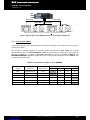
7.4.2 Connecting the 8XT and SB118 to the LA4
The 8XT and SB118 enclosures connect to the LA4 outputs as follows: channels 1 and 3 are dedicated to one SB118
enclosure each, and channels 2 and 4 to 8XT enclosures. Each 8XT enclosure can be paired in parallel with an
additional 8XT. Therefore, a single LA4 amplified controller can drive up to four 8XT and two SB118 enclosures (see
Figure 7).
A maximum of one SB118 enclosure can be connected per LA4 output channel 1 or 3.
Note: The system resources are optimized for two or four 8XT and two SB118 per LA4.
!
CAUTION

8
88
8XT
XTXT
XT
C
CC
COAXIAL ENCLOSURE
OAXIAL ENCLOSUREOAXIAL ENCLOSURE
OAXIAL ENCLOSURE
user manual
user manualuser manual
user manual
VERSION 1.3
8XT_UM_ML_1-3
w w w . l - a c o u s t i c s . c o m
16
1616
16 en
Figure 7: Four 8XT and two SB118 enclosures connected to an LA4 controller
7.4.3 [8XT_SB118] preset
The [8XT_SB118] preset features a HF shelving EQ for FOH applications. The crossover frequency between the LF
and HF sections is set at 100 Hz.
Activate the LOAD PRESET menu from the LA4 amplified controller front panel and then select the [8XT_SB118]
preset. Refer to the ‘‘LA4’’ user manual for additional instructions. The preset is also accessible using the
LA NETWORK MANAGER software (refer to ‘‘LA NETWORK MANAGER’’ user manual). Accessible parameters
in ‘‘HYBRID’’ mode are shown in the following chart:
Table 4: Accessible parameters in ‘‘HYBRID’’ mode
Accessible (O) and blocked (X) parameters
LA4 Inputs/Outputs
Elements to connect Preset
assignments* Mute Gain Delay Polarity
IN A Input signal A IN_A X O
O
O
IN B Input signal B IN_B X O
O
O
OUT 1 SB118 enclosure SB_A O
O
O
O
OUT 2 8XT enclosure
PA_A O
O
O
X
OUT 3 SB118 enclosure
SB_B O
O
O
O
OUT 4 8XT enclosure
PA_B O
O
O
X
* IN: input signal. A, B: channel A, B. PA: passive enclosure. SB: subwoofer enclosure.
IN A
OUT 2 (IN A)
OUT 1
(IN A)
OUT 3 (IN B)
IN B
Note:
This drawing
is only a cabling scheme and
does
not
represent a
valid configuration.
OUT 4
(IN B)

8XT_UM_ML_1-3
w w w . l - a c o u s t i c s . c o m
17
1717
17 en
EN
8
88
8 CARE AND MAINTENANCE
CARE AND MAINTENANCECARE AND MAINTENANCE
CARE AND MAINTENANCE
8.1 Maintenance information
The L-ACOUSTICS® 8XT enclosure is a technical product designed for various, intensive indoor and outdoor sound
reinforcement applications. To fulfill such demanding conditions L-ACOUSTICS® has designed the 8XT enclosure with
high-grade and reliable components:
• Weather-resistant transducers.
• Baltic birch plywood cabinet.
• Polyester-coated steel grill covered by a non biodegradable “Airnet” fabric.
• Oxidation-resistant screws and rigging points.
However, in order to ensure product performance and safety, it is essential to frequently inspect the 8XT cabinet and
its internal components. These checks need to be done on a regular basis depending on the conditions of system use.
The testing procedure consists of three steps as described in section 8.2. If a transducer needs to be repaired or
replaced, apply the corresponding procedure in section 8.3.
8.2 Testing procedure
8.2.1 Check of transducer and enclosure acoustic behavior
Connect a sweep frequency generator to the active input of the LA4 amplified controller. Apply a sweep from 65 Hz to
20 kHz with a maximum voltage of 0.2 volts (-12 dBu, -14 dBV): the sound should remain pure and free of any
unwanted noise. If not, check the mechanical assemblies and, if necessary, contact an L-ACOUSTICS® authorized
representative to repair or replace the damaged components (see also section 8.3).
0.2 volts is a maximum value that can generate very high sound levels at given frequencies.
Use ear protection to set the sound level before testing.
Whenever a transducer is reconnected, wiring polarity should be checked using a phase checking device. If a transducer
is out of phase, invert the cables connected to its electrical sockets. The connecting procedures are given in section 8.3.
8.2.2 Check of mechanical assembly and rigging parts
Inspect the general aspect of assembly and check that screws are locked tight (on rigging elements, loudspeaker,
diaphragm, and grill). Check the quality of contact and locking action of the Speakon® sockets. Also check the integrity
of rigging elements (no signs of deformation, fissure, or corrosion). If necessary, contact an L-ACOUSTICS® authorized
representative to replace the damaged components.
8.2.3 Check of external aspect
Remove the dust from the grill with a vacuum device. If needed, repaint the cabinet.
If paint is applied, protect mechanical parts.
Do not apply paint to the front grill fabric as it could fill the fabric holes and deteriorate the acoustic
transparency of the material.
!
IMPORTANT
!
WARNING

8
88
8XT
XTXT
XT
C
CC
COAXIAL ENCLOSURE
OAXIAL ENCLOSUREOAXIAL ENCLOSURE
OAXIAL ENCLOSURE
user manual
user manualuser manual
user manual
VERSION 1.3
8XT_UM_ML_1-3
w w w . l - a c o u s t i c s . c o m
18
1818
18 en
8.3 Transducer service
8.3.1 LF loudspeaker
If damaged, the 8” LF loudspeaker should be removed and repaired or replaced as described below. Recone kits are
available. Alternatively, reconing can be performed by L-ACOUSTICS® (see section 8.4).
8” loudspeaker removing procedure
1. Put the enclosure on a flat surface and roll both rubber bands back away from the grill.
2. Remove the grill: remove the 4 Torx® screws, lift up the grill (use the flat screwdriver).
3. Remove the loudspeaker coaxial assembly: remove the 4 hex screws with split and flat washers,
lift up the loudspeaker (use the flat screwdriver).
4. Place the loudspeaker coaxial assembly in front of the enclosure with LF cone facing the flat surface.
5. Disconnect the four cables (2 red and 2 black ones) from the transducers electrical sockets.
6. Remove both hex screws located on the HF heat dissipation plate.
7. Remove the HF assembly.
8” loudspeaker replacing procedure
1. Place the LF speaker in front of the enclosure with cone facing the flat surface, LF electrical connectors
towards the user (in this way, the shorter HF cables cannot reach the LF sockets).
2. Install the HF assembly on the LF loudspeaker, red-labeled electrical pins on the same side, and screw in both
hex screws through the HF heat dissipation plate (5 N.m/45 in.lbf, thread-locker).
3. Connect the four cables to the transducers electrical sockets: both short cables connect to the HF
sockets and both long cables to the LF sockets (for both transducers: red cable to the red-labeled pin
and black cable to the unlabeled pin).
4. Install the loudspeaker assembly in the enclosure and screw in the 4 hex screws with split and flat washers:
into each hex screw insert a split washer and then a flat washer (following this sequence) and screw in the
assembly to one of the four locations (5 N.m/45 in.lbf).
5. Install the grill (logo oriented towards the pole mount socket) and screw in the 4 Torx® screws
at 10 mm/0.5 inch besides the previous drillings (3 N.m/27 in.lbf).
6. Put in place both rubber bands on the grill.
8.3.2 HF driver or diaphragm
If damaged, the HF diaphragm or the full HF driver should be removed and replaced as described below.
HF driver or diaphragm removing procedure
1. Put the enclosure on a flat surface and roll both rubber bands back away from the grill.
2. Remove the grill: remove the 4 Torx® screws, lift up the grill (use the flat screwdriver).
3. Remove the loudspeaker coaxial assembly: remove the 4 hex screws with split and flat washers,
lift up the loudspeaker (use the flat screwdriver).
4. Place the loudspeaker coaxial assembly with LF cone facing the flat surface.
5. Disconnect both cables (1 red and 1 black ones) from the HF driver electrical sockets.
6. To remove the diaphragm only: unscrew the 4 Pozidriv® screws from the back cover of the driver,
and pull the diaphragm out from the magnet.
To remove the full HF driver: unscrew both hex screws from the heat dissipation plate, remove the HF
assembly from the LF speaker, unscrew both Torx® screws located on the rear face of the heat dissipation
plate, remove the driver from the plate.
La page est en cours de chargement...
La page est en cours de chargement...
La page est en cours de chargement...
La page est en cours de chargement...
La page est en cours de chargement...
La page est en cours de chargement...
La page est en cours de chargement...
La page est en cours de chargement...
La page est en cours de chargement...
La page est en cours de chargement...
La page est en cours de chargement...
La page est en cours de chargement...
La page est en cours de chargement...
La page est en cours de chargement...
La page est en cours de chargement...
La page est en cours de chargement...
La page est en cours de chargement...
La page est en cours de chargement...
La page est en cours de chargement...
La page est en cours de chargement...
La page est en cours de chargement...
La page est en cours de chargement...
La page est en cours de chargement...
La page est en cours de chargement...
-
 1
1
-
 2
2
-
 3
3
-
 4
4
-
 5
5
-
 6
6
-
 7
7
-
 8
8
-
 9
9
-
 10
10
-
 11
11
-
 12
12
-
 13
13
-
 14
14
-
 15
15
-
 16
16
-
 17
17
-
 18
18
-
 19
19
-
 20
20
-
 21
21
-
 22
22
-
 23
23
-
 24
24
-
 25
25
-
 26
26
-
 27
27
-
 28
28
-
 29
29
-
 30
30
-
 31
31
-
 32
32
-
 33
33
-
 34
34
-
 35
35
-
 36
36
-
 37
37
-
 38
38
-
 39
39
-
 40
40
-
 41
41
-
 42
42
-
 43
43
-
 44
44


L-Acoustics 8XT Manuel utilisateur
- Catégorie
- Haut-parleurs
- Taper
- Manuel utilisateur
dans d''autres langues
- English: L-Acoustics 8XT User manual