

Document
Document Details
Verkada Inc. 406 E 3rd Ave, San Mateo, CA 94401
All specifications are subject to change without notice
Copyright © 2023 Verkada Inc. All rights reserved.
V1.4 (20230829)
(V1.0 first published 20230315)
Firmware
Firmware version can be verified on
Verkada Command command.verkada.com.
Product Model
This install guide pertains to model BC82-HW.
2

Introduction
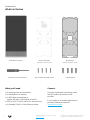
What’s in the box
What you’ll need
●A working internet connection
●A smartphone or laptop
●A #2 Phillips screwdriver or
power drill with a #2 Phillips driver bit
●3/16 inch (4.76 mm) drill bit for wall anchors
●A shielded Cat5 or Cat6 Ethernet cable
Verkada Inc. 406 E 3rd Ave, San Mateo, CA 94401
All specifications are subject to change without notice
Copyright © 2023 Verkada Inc. All rights reserved.
BC82 Alarm Console
3
Mount Plate
(Attached to Alarm Console)
Connect
For easy registration and setup, scan
the QR code on the back of the
product.
If you prefer to manually register your
product, please proceed to:
verkada.com/start
T10 Security Torx Screwdriver
Mount Template
(Attached to Alarm Console)
4 M4 x 25mm PH2 Wall Screws 4 Wall Anchors

Introduction
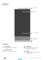
Overview 1/2
Verkada Inc. 406 E 3rd Ave, San Mateo, CA 94401
All specifications are subject to change without notice
Copyright © 2023 Verkada Inc. All rights reserved.
4
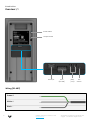
LED Behavior
Solid Orange
Console is on and booting up.
Flashing Orange
Console is updating firmware.
Status LED
Speaker & Buzzer
10.1” Touchscreen
Flashing Blue
Console can receive events but
cannot reach the server.
Solid Blue
Console is running, connected, and
receiving events.
Camera
Microphone


Introduction
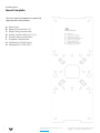
Mount Template
Verkada Inc. 406 E 3rd Ave, San Mateo, CA 94401
All specifications are subject to change without notice
Copyright © 2023 Verkada Inc. All rights reserved.
6
A
B
C
D
E
F
G
H
Wall mount
Square Junction Box (4”)
Single Gang Junction Box
Round Junction Box (4” & 3-½”)
Double Gang Junction Box
European Junction Box
VESA Mount (100x100 mm)
Verkada ACC-CON-STD-1
Use the mount template to mark the
appropriate hole pattern.

Verkada Inc. 405 E 4th Ave, San Mateo, CA 94401
All specifications are subject to change without notice
Copyright © 2022 Verkada Inc. All rights reserved.
Introduction
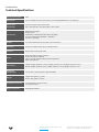
Technical Specifications
Power Consumption 25W
Battery Life 12-hour battery backup (34.4 watt-hour rechargeable lithium-ion battery)
Power Input
Parameters
DC 10V-36V VDC input; 2.8A-1.29A
PoE+ (802.3at) 42V-57V VDC input; 0.60A-0.44A
Connectivity
Ethernet 10/100Mbps
Bluetooth 5.0
Dual Band (2.4GHz/5GHz) WiFi, 802.11 ac/abgn
Sub-GHz transceiver (863MHz - 928MHz)
2x USB 2.0, 1x RS485
Display 10.1” LED-backlit multi-touch, 1960 x 1200 resolution
Processor Quad-core ARM Cortex-A53 64-bit processor
Camera 8MP Camera, 1080p HD video
Audio
Mono speaker (90 dB at 1 meter)
Buzzer (90 dB at 3 meters)
3.5mm jack for external self-powered speakers
Dual microphones
Dimensions Tablet: Height: 309.9mm / 12.2 in; Width: 161.3mm / 6.4 in; Depth: 40.3mm / 1.6 in
Mount: Length: 281.9mm / 11.1 in; Width: 113.9mm / 4.5 in; Height: 17.5mm / 0.7 in
Operating
Temperature 0°C to 40°C / 32°F to 104°F, 5-90% humidity
Weight Tablet: 1,240 grams / 2.7 lbs
Mount: 400 grams / 0.9 lbs
Included Accessories T10 screwdriver, x4 wall screws,
x4 drywall anchors
Mounting Options Wall Mount Bracket
7

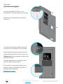
Installation
Connect and register
Verkada Inc. 406 E 3rd Ave, San Mateo, CA 94401
All specifications are subject to change without notice
Copyright © 2023 Verkada Inc. All rights reserved.
8
Use the provided T10 Security Torx
screwdriver to loosen the security screw.
Slide the mount plate downwards to
remove it.
Connect the Ethernet cable to the PoE
connector on the back of the Console.
Press the power button once and wait
for the Status LED and screen to turn on.
Please note: Bootup sequence may take
several seconds.
For easy registration and setup, scan
the QR code on the product.
If you prefer to manually register your
product, refer to the serial number on
screen and proceed to:
verkada.com/start

Installation
Mounting 1/2
Verkada Inc. 406 E 3rd Ave, San Mateo, CA 94401
All specifications are subject to change without notice
Copyright © 2023 Verkada Inc. All rights reserved.
9
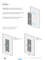
Please note: Avoid mounting the Console in
direct sunlight for optimal device performance.
Use the mount template to mark the appropriate
hole pattern on the mounting surface.
Use the wall anchors and screws to attach the
mount plate onto the desired surface.
A
B
C
D
E
F
G
H
Wall mount
Square Junction Box (4”)
Single Gang Junction Box
Round Junction Box (4” & 3-½”)
Double Gang Junction Box
European Junction Box
VESA Mount (100x100 mm)
Verkada ACC-CON-STD-1
Use the mount template to mark the
correct hole pattern.
Cables can be routed through the
surface, or along the surface.
Option 1
Cable routing through
the surface
Option 2
Cable routing
along the surface

Installation
Mounting 2/2
Verkada Inc. 406 E 3rd Ave, San Mateo, CA 94401
All specifications are subject to change without notice
Copyright © 2023 Verkada Inc. All rights reserved.
10
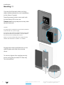
Connect the Ethernet cable, and any
other cables relevant to your installation,
to the Alarm Console.
Press the power button once and wait
for the Status LED to turn on.
Please note: Bootup sequence may take
several seconds.
Caution:
The equipment is intended to be powered by external
or IEEE 802.3at PoE+ power supply.
The power supply shall be certified which comply with
the requirements of IEC/EN 62368-1 or IEC/EN 60950-1
for a PS2 source or limited power source.
Note: For US and Canada the power supply shall be
certified with standard UL 62368-1 or UL 60950-1.
Engage the three hook features on the
mount plate and slide the console
down.
To secure, tighten the captive security
screw, using the provided T10 Security
Torx screwdriver.

Appendix
BC82 Compliance
Verkada Inc. 406 E 3rd Ave, San Mateo, CA 94401
All specifications are subject to change without notice
Copyright © 2023 Verkada Inc. All rights reserved.
11
FCC
Statement
FEDERAL COMMUNICATIONS COMMISSION INTERFERENCE STATEMENT
This equipment has been tested and found to comply with the limits for a Class B digital device, pursuant to part 15 of
the FCC Rules. These limits are designed to provide reasonable protection against harmful interference in a residential
installation. This equipment generates, uses and can radiate radio frequency energy and, if not installed and used in
accordance with the instructions, may cause harmful interference to radio communications. However, there is no
guarantee that interference will not occur in a particular installation. If this equipment does cause harmful
interference to radio or television reception, which can be determined by turning the equipment off and on, the user is
encouraged to try to correct the interference by one or more of the following measures:
-Reorient or relocate the receiving antenna.
-Increase the separation between the equipment and receiver.
-Connect the equipment into an outlet on a circuit different from that to which the receiver is connected.
-Consult the dealer or an experienced radio/TV technician for help.
This device complies with Part 15 of the FCC Rules. Operation is subject to the following two conditions:
(1) this device may not cause harmful interference, and
(2) this device must accept any interference received, including interference that may cause undesired operation.
IMPORTANT NOTE:
FCC Radiation Exposure Statement :
This equipment complies with FCC radiation exposure limits set forth for an uncontrolled environment. This equipment
should be installed and operated with minimum distance 20cm between the radiator & your body.
Any changes or modifications not expressly approved by the party responsible for compliance could void your
authority to operate the equipment.
IC Statement Innovation, Science and Economic Development Canada(ISED)Compliance Statement
This device complies with ISED’s licence-exempt RSS standard(s).
Operation is subject to the following two conditions: (1) this device may not cause interference, and (2) this device
must accept any interference, including interference that may cause undesired operation of the device.
IMPORTANT NOTE:
IC Radiation Exposure Statement:
This equipment complies with IC RSS-102 radiation exposure limits set forth for an uncontrolled environment. This
equipment should be installed and operated with minimum distance 20cm between the radiator & your body.
Caution:
The device for operation in the band 5150–5250 MHz is only for indoor use to reduce the potential for harmful
interference to co-channel mobile satellite systems;
This equipment supports DFS (Dynamic Frequency Selection) to minimize interference and/or damage caused by the
high-power radars that are allocated as primary users (i.e. priority users) of the bands 5250-5350 MHz and 5470-5725
MHz.
Le présent appareil est conforme aux CNR d’ ISED applicables aux appareils radio exempts de licence. L’exploitation
est autorisée aux deux conditions suivantes : (1) le dispositif ne doit pas produire de brouillage préjudiciable, et (2) ce
dispositif doit accepter tout brouillage reçu, y compris un brouillage susceptible de provoquer un fonctionnement
indésirable.
NOTE IMPORTANTE:
Déclaration d'exposition aux rayonnements d'IC :
Cet équipement est conforme aux limites d'exposition aux rayonnements IC RSS-102 définies pour un environnement
non contrôlé. Cet équipement doit être installé et utilisé avec une distance minimale de 20 cm entre le radiateur et
votre corps.
Avertissement:
Le dispositif fonctionnant dans la bande 5150-5250 MHz est réservé uniquement pour une utilisation à l’intérieur afin
de réduire les risques de brouillage préjudiciable aux systèmes de satellites mobiles utilisant les mêmes canaux;
Cet équipement prend en charge DFS (Dynamic Frequency Selection) pour minimiser les interférences et/ou les
dommages causés par les radars haute puissance qui sont attribués en tant qu'utilisateurs principaux (c'est-à-dire
les utilisateurs prioritaires) des bandes 5250-5350 MHz et 5470-5725 MHz.

Verkada Inc. 406 E 3rd Ave, San Mateo, CA 94401
All specifications are subject to change without notice
Copyright © 2023 Verkada Inc. All rights reserved.
12
Appendix
Support
Thank you for purchasing this Verkada product. If for any reason
you're experiencing issues or need assistance, please contact our
24/7 Technical Support Team immediately.
Sincerely,
The Verkada Team
verkada.com/support
-
 1
1
-
 2
2
-
 3
3
-
 4
4
-
 5
5
-
 6
6
-
 7
7
-
 8
8
-
 9
9
-
 10
10
-
 11
11
-
 12
12


dans d''autres langues
- English: Verkada BC82 Installation guide
Documents connexes
-
Verkada BK11/BK21 Alarm Keypad Guide d'installation
-
-
-
Verkada AD33 Guide d'installation
-
-
-
-
Verkada BR32 Guide d'installation
-
-