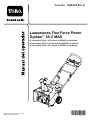
Toro Flex-Force Power System 60V MAX Snowthrower Manuel utilisateur
- Taper
- Manuel utilisateur

Form No. 3460-964 Rev A
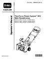
Flex-Force Power System™ 60V MAX
Snowthrower
39901 , 39901T , 39902
Lanzanieves Flex-Force Power System™
60V MAX39901 , 39901T , 39902
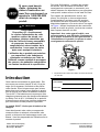
Soufeuse à neige Flex-Force Power
System™ 60V MAX39901 , 39901T , 39902
www .T oro.com.
*3460-964*


Form No. 3460-961 Rev A
Flex-Force Power System
™
60V
MAX Snowthrower
Model No. 39901 —Serial No. 414300000 and Up
Model No. 39901T —Serial No. 414300000 and Up
Model No. 39902 —Serial No. 414300000 and Up
Register at www .T oro.com.
Original Instructions (EN)
*3460-961*

For assistance, please see
www .T oro.com/support
for instructional videos
or contact 1-888-384-9939
before returning this
product.
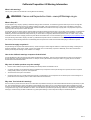
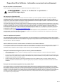
W ARNING
CALIFORNIA
Proposition 65 W arning
The power cord on this product contains
lead, a chemical known to the State
of California to cause birth defects
or other reproductive harm. W ash
hands after handling.
Use of this product may cause exposure
to chemicals known to the State of
California to cause cancer , birth defects,
or other reproductive harm.
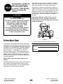
Introduction
This machine is intended to be used by residential
homeowners. It is designed for removing up to 30 cm
(12 inches) of snow from patios, sidewalks, and small
driveways. It is not designed for removing materials
other than snow , nor is it designed for clearing of f
gravel surfaces. It is designed to use T oro 60V
lithium-ion battery packs. These battery packs are
designed to be charged only by T oro 60V lithium-ion
battery chargers. Using this product for purposes
other than its intended use could prove dangerous to
you and bystanders.
Model 39901T does not include a battery or a
charger .
Read this information carefully to learn how to operate
and maintain your product properly and to avoid
injury and product damage. Y ou are responsible for
operating the product properly and safely .
V isit www .T oro.com for more information, including
safety tips, training materials, accessory information,
help nding a dealer , or to register your product.
Whenever you need service, genuine T oro parts, or
additional information, contact an Authorized Service
Dealer or T oro Customer Service and have the model
and serial numbers of your product ready . Figure 1
identies the location of the model and serial numbers
on the product. W rite the numbers in the space
provided.
Important: W ith your mobile device, you can
scan the QR code (if equipped) on the serial
number plate to access warranty , parts, and other
product information.
g427629
Figure 1
1. Model number , serial number , and QR code location
Model No.
Serial No.
© 2023—The T oro® Company
81 1 1 L yndale A venue South
Bloomington, MN 55420
2
Contact us at www .T oro.com.
Printed in Mexico
All Rights Reserved

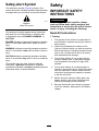
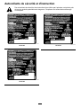
Safety-Alert Symbol
The safety-alert symbol ( Figure 2 ) shown in this
manual and on the machine identies important safety
messages that you must follow to prevent accidents.
g000502
Figure 2
Safety-alert symbol
The safety-alert symbol appears above information
that alerts you to unsafe actions or situations and
is followed by the word DANGER ,W ARNING , or
CAUTION .
DANGER indicates an imminently hazardous situation
which, if not avoided, will result in death or serious
injury .
W ARNING indicates a potentially hazardous situation
which, if not avoided, could result in death or serious
injury .
CAUTION indicates a potentially hazardous situation
which, if not avoided, may result in minor or moderate
injury .
This manual uses two other words to highlight
information. Important calls attention to special
mechanical information and Note emphasizes general
information worthy of special attention.
Safety
IMPORT ANT SAFETY
INSTRUCTIONS
W ARNING
When using an electric machine, always
read and follow basic safety warnings and
instructions to reduce the risk of re, electric
shock, or injury , including the following:
Read All Instructions
I. T raining
1. The operator of the machine is responsible for
any accidents or hazards occurring to others or
their property .
2. Read and understand the contents of this
Operator ’ s Manual before you start the machine.
Ensure that everyone using this machine knows
how to use it, knows how to shut it of f quickly ,
and understands the warnings.
3. Do not allow children to use or play with the
machine, battery pack, or the battery charger;
local regulations may restrict the age of the
operator .
4. Do not allow children or untrained people to
operate or service this device. Allow only people
who are responsible, trained, familiar with the
instructions, and physically capable to operate
or service the device.
5. Before using the machine, battery pack, and
battery charger , read all the instructions and
cautionary markings on these products.
6. Become familiar with the controls and proper
use of the machine, battery pack, and battery
charger .
3

II. Preparation
1. Keep bystanders and children out of the
operating area.
2. Never allow children to operate the machine.
3. Do not operate the machine without all guards
and other safety devices in place and functioning
properly on the machine.
4. Inspect the area where you will use the machine
and remove all objects that could interfere with
the operation of the machine or that the machine
could throw .
5. Use only the battery pack specied by T oro.
Using other accessories and attachments may
increase the risk of injury and re.
6. Plugging the battery charger into an outlet that
is not 120 V can cause a re or electric shock.
Do not plug the battery charger into an outlet
other than 120 V .
7. Do not use a damaged or modied battery
pack or battery charger , which may exhibit
unpredictable behavior that results in re,
explosion, or risk of injury .
8. If the supply cord to the battery charger is
damaged, contact an Authorized Service Dealer
to replace it.
9. Charge the battery pack with only the battery
charger specied by T oro. A charger suitable for
1 type of battery pack may create a risk of re
when used with another battery pack.
10. Charge the battery pack in a well-ventilated area
only .
1 1. Follow all charging instructions and do
not charge the battery pack outside of the
temperature range specied in the instructions.
Otherwise, you may damage the battery pack
and increase the risk of re.
12. Dress properly—W ear appropriate clothing,
including eye protection; long pants or trousers;
substantial, slip-resistant rubber boots; and
hearing protection. T ie back long hair and do not
wear loose clothing or loose jewelry that can get
caught in moving parts.
III. Operation
1. Contact with the moving rotor will cause serious
injury . Keep your hands and feet away from all
moving parts of the machine. Keep clear of any
discharge opening.
2. Stay behind the handles and away from the
discharge opening while operating the machine.
3. Using this machine for purposes other than its
intended use could prove dangerous to you and
bystanders.
4. Prevent unintentional starting—Ensure that
the electric-start button is removed from the
machine before connecting the battery pack and
handling the machine.
5. Use your full attention while operating the
machine. Do not engage in any activity that
causes distractions; otherwise, injury or property
damage may occur .
6. Shut of f the machine, remove the electric-start
button, remove the battery pack from the
machine, and wait for all movement to stop
before adjusting, servicing, cleaning, or storing
the machine.
7. Remove the battery pack and electric-start
button from the machine whenever you leave it
unattended or before changing accessories.
8. Do not force the machine—Allow the machine to
do the job better and safer at the rate for which it
was designed.
9. Stay alert—W atch what you are doing and use
common sense when operating the machine.
Do not use the machine while ill, tired, or under
the inuence of alcohol or drugs.
10. Operate the machine only in good visibility and
appropriate weather conditions.
1 1. Use extreme caution when reversing or pulling
the machine toward you.
12. Keep proper footing and balance at all times,
especially on slopes. Use extreme caution when
changing directions on slopes. Do not operate
the machine on exceedingly steep slopes. W alk,
never run with the machine.
13. When not actively clearing snow , disengage
power to the auger .
14. Do not use the machine on a gravel surface.
15. Do not direct the discharge material toward
anyone. A void discharging material against a
wall or obstruction; material may ricochet toward
you. Shut of f the machine when crossing gravel
surfaces.
16. Exercise extreme caution when operating the
machine on or crossing drives, walks, or roads.
Stay alert for hidden hazards or traf c.
4

17. If the machine strikes an object or starts to
vibrate, immediately shut of f the machine,
remove the electric-start button, remove the
battery pack, and wait for all movement to stop
before examining the machine for damage.
Make all necessary repairs before resuming
operation.
18. Shut of f the machine whenever you leave the
operating position for any reason.
19. Shut of f the machine and remove the
electric-start button before unclogging the
machine and always use a stick or a cleanout
tool to remove the clog.
20. Shut of f the machine, remove the electric-start
button, and remove the battery pack(s) from the
machine before loading the machine for hauling.
21. Never operate the machine at high transport
speeds on slippery surfaces.
22. Under abusive conditions, the battery pack may
eject liquid; avoid contact. If you accidently
come into contact with the liquid, ush with
water . If the liquid contacts your eyes, seek
medical help. Liquid ejected from the battery
pack may cause irritation or burns.
23. Do not expose a battery pack or tool to re or
excessive temperature. Exposure to re or
temperature above 130°C (265°F) may cause
explosion.
24. CAUTION—A mistreated battery pack may
present a risk of re, explosion, or chemical
burn.
•Do not disassemble the battery pack.
•Replace the battery pack with a genuine
T oro battery pack only; using another type of
battery pack may cause a re or risk of injury .
•Keep battery packs out of the reach of
children and in the original packaging until
you are ready to use them.
IV . Maintenance and Storage
1. Shut of f the machine, wait for all moving parts
to stop, remove the electric-start button, and
remove the battery pack(s) from the machine
before adjusting, servicing, cleaning, or storing
the machine.
2. Do not attempt to repair the machine except as
indicated in the instructions. Have an Authorized
Service Dealer perform service on the machine
using identical replacement parts.
3. W ear gloves and eye protection when servicing
the machine.
4. When servicing the rotor , be aware that the rotor
can still move even though the power source
is of f.
5. For best performance, use only genuine T oro
replacement parts and accessories. Other
replacement parts and accessories could be
dangerous, and such use could void the product
warranty .
6. Maintain the machine—Keep handles dry , clean,
and free from oil and grease. Keep guards
in place and in working order . Use identical
replacement parts only .
7. Check all fasteners at frequent intervals for
proper tightness to ensure that the machine is in
safe working condition.
8. Check the machine for damaged parts. Check
for misaligned and binding moving parts, broken
parts, mounting, and any other condition that
may af fect its operation. Unless indicated in the
instructions, have an Authorized Service Dealer
repair or replace a damaged guard or part.
9. When the battery pack is not in use, keep it
away from metal objects such as paper clips,
coins, keys, nails, and screws that can make a
connection from 1 terminal to another . Shorting
the battery terminals may cause burns or a re.
10. When you are not using the machine, store it
indoors in a dry , secure place out of the reach
of children.
1 1. When storing the machine for more than 30
days, refer to Storage ( page 19 ) for important
information.
SA VE THESE
INSTRUCTIONS
5

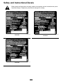
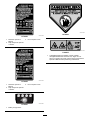
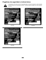
Safety and Instructional Decals
Safety decals and instructions are easily visible to the operator and are located near any area
of potential danger . Replace any decal that is damaged or missing.
decal161-2162
161-2162
decal161-2164
161-2164
decal161-2166
161-2166
6

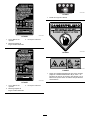
decal137-2257
137-2257
1. W arning—read the Operator ’ s Manual .
3. Thrown object hazard—keep bystanders away .
2. Cutting/dismemberment of hand hazard, impeller;
cutting/entanglement of foot hazard, auger—stay away from
moving parts; keep all guards and shields in place; shut of f
the engine and remove the key before leaving the machine;
read the Operator ’ s Manual before performing maintenance.
decal137-2258
137-2258
1. T o start the engine, bring the bail to the handle and press
the ignition button.
2. ECO
decal137-9462
137-9462
decal137-9463
137-9463
1. The battery pack is charging.
2. The battery pack is fully charged.
3. The battery pack is over or under the appropriate temperature range.
4. Battery pack charging fault
7

decal137-9456
137-9456
1. Read the Operator ’ s
Manual .
3. Do not expose to rain.
2. Keep away from open re
or ames.
decal137-9455
137-9455
1. Read the Operator ’ s
Manual .
3. Do not expose to rain.
2. Keep away from open re
or ames.
decal137-9461
137-9461
1. Battery charge status
decal147-9420
147-9420
decal1 14-9035
1 14-9035
1. Cutting/dismemberment hazard of hand, impeller;
cutting/dismemberment hazard of foot, auger—do not
place your hand in the chute; remove the key and read the
Operator ’ s Manual before performing maintenance.
8

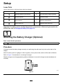
Setup
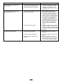
Loose Parts
Use the chart below to verify that all parts have been shipped.
Procedure Description
Qty .
Use
1
Mounting hardware (not included)
2
Mount the battery charger (optional).
2
No parts required
–
Unfold the handle.
3
Chute deector
1
Install the chute deector .
4
Chute-control rod
1 Install the chute-control rod.
Important: The battery pack is not fully charged when you purchase it. Before using the machine for
the rst time, refer to Charging the Battery Pack ( page 16 ) .
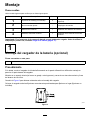
1
Mounting the Battery Charger (Optional)
Parts needed for this procedure:
2
Mounting hardware (not included)
Procedure
If desired, mount the battery charger securely on a wall using the wall-mount key holes on the back of the
charger .
Mount it indoors (such as a garage or other dry place), near a power outlet, and out of the reach of children.
Refer to Figure 3 for assistance in mounting the charger .
Slide the charger over the appropriately positioned hardware to secure the charger in place (hardware not
included).
g290534
Figure 3
9

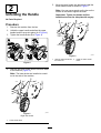
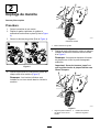
2
Unfolding the Handle
No Parts Required
Procedure
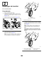
1. Remove the machine from the box.
2. Unfold the upper handle and allow the upper
handle knobs to snap into place (A of Figure 4 ).
3. T ighten the handle knobs (B of Figure 4 ).
g282574
Figure 4
4. Remove the lower handle knobs from both sides
of the machine ( Figure 5 ).
Note: The lower knobs are installed to a weld
nut in the side of the machine.
g303594
Figure 5
Right side shown
1. Lower handle knob
5. Move the lower handle into place and install the
lower handle knobs as shown in Figure 6 .
Note: Y ou may use a wrench on the hex on the
outside of the knob to tighten the knob.
Important: T ighten the knobs until the
handlebar touches the side plate with no gap.
g303595
Figure 6
1. Align the lower handle with
the weld nuts.
2. Install the lower handle
knobs.
10

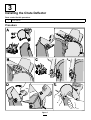
3
Installing the Chute Deector
Parts needed for this procedure:
1
Chute deector
Procedure
g316999
Figure 7
1 1

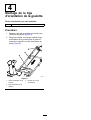
4
Installing the Chute-Control
Rod
Parts needed for this procedure:
1
Chute-control rod
Procedure
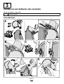
1. Ensure that the chute is facing forward ( Figure
8).
2. With the handle facing forward, install the
chute-control rod into the guide and push it down
until it snaps into place ( Figure 8 ).
g282249
Figure 8
1. Chute-control guide 3. Chute-control handle
2. Chute-control rod
12

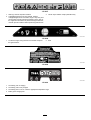
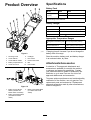
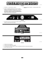
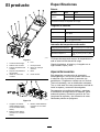
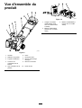
Product Overview
g318456
Figure 9
1. Discharge chute 6. Headlight
2. Chute deector 7. ECO switch
3. Chute-deector handle
8. Electric-start button
4. Battery-compartment lid 9. Bail
5. Chute-control rod
10. Rotor blades
g359246
Figure 10
1. Battery charger Model
88602 (included with
Model 39901 and 39902)
3. Battery pack Model 88660
(2 included with Model
39902)
2. Battery pack Model 88675
(included with Model
39901)
Specications
Battery Pack
Model 88660 88675
6.0 Ah 7.5 AhBattery pack
capacity
324 Wh 405 Wh
Battery manufacturer rating = 60V maximum and 54V nominal.
Actual voltage varies with load.
Battery Charger
Model 88602
T ype
60V MAX Lithium-Ion Battery Charger
Input
120V AC ~2.0A, 60Hz
Output 60V DC 2.0A MAX
Appropriate T emperature Ranges
Charge/store the battery pack
at
5°C (41°F) to 40°C (104°F)*
Use the machine at
-30°C (-22°F) to 23°C (73°F)*
Store the machine at -30°C (-22°F) to 49°C (120°F)*
*Charging time will increase if you do not charge the
battery within this range.
Store the machine, battery pack, and battery charger
in an enclosed clean, dry area.
Attachments/Accessories
A selection of T oro approved attachments and
accessories is available for use with the machine
to enhance and expand its capabilities. Contact
your Authorized Service Dealer or authorized T oro
distributor or go to www .T oro.com for a list of all
approved attachments and accessories.
T o ensure optimum performance and continued safety
certication of the machine, use only genuine T oro
replacement parts and accessories. Replacement
parts and accessories made by other manufacturers
could be dangerous.
13

Operation
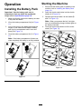
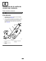
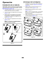
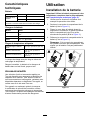
Installing the Battery Pack
Important: Use the battery pack only in
temperatures that are within the appropriate
range; refer to Specications ( page 13 ) .
1. Make sure that the vents on the battery are clear
of any dust and debris.
2. Lift up the battery-compartment lid (A of Figure
1 1 ).
3. Line up the cavity in the battery pack with the
tongue on the machine and slide the battery
pack into the compartment until it locks into
place (B of Figure 1 1 ).
4. Close the battery-compartment lid (C of Figure
1 1 ).
Note: If the battery-compartment lid does not
close completely , the battery is not fully installed.
g282250
Figure 1 1
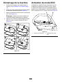
Starting the Machine
1. Ensure that the battery pack is installed in the
machine; refer to Installing the Battery Pack
( page 14 ) .
2. Insert the electric-start button into the electric
starter (A of Figure 12 ).
3. Squeeze the bail and hold it to the handle (B
and C of Figure 12 ).
Note: When you squeeze the bail, the lights
turn on and the battery-charge indicator lights on
the battery illuminate.
4. Press the electric-start button until the motor
starts (D of Figure 12 ).
g288479
Figure 12
14

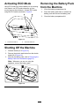
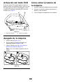
Activating ECO Mode
Using ECO mode may extend battery life by reducing
rotor speed; use ECO mode whenever you are
moving snow a short distance. Activate ECO mode
using the ECO switch as shown in Figure 9 .
g318457
Figure 13
1. T urn ECO mode on 2. T urn ECO mode of f
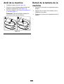
Shutting Off the Machine
1. Release the bail (A of Figure 14 ).
2. Remove the electric-start button from the electric
starter (B of Figure 14 ).
3. Remove the battery pack; refer to Removing the
Battery Pack from the Machine ( page 15 ) .
Note: Whenever you are not using the
appliance, remove the battery pack.
g247446
Figure 14
Removing the Battery Pack
from the Machine
1. Lift up the battery-compartment lid.
2. Press the battery pack-latch to release the
battery pack and remove the battery pack.
3. Close the battery-compartment lid.
15

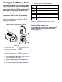
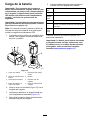
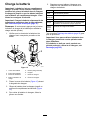
Charging the Battery Pack
Important: The battery pack is not fully charged
when you purchase it. Before using the tool for
the rst time, place the battery pack in the charger
and charge it until the LED display indicates the
battery pack is fully charged. Read all safety
precautions.
Important: Charge the battery pack only in
temperatures that are within the appropriate
range; refer to Specications ( page 13 ) .
Note: At any time, press the battery-charge-indicator
button on the battery pack to display the current
charge (LED indicators).
1. Ensure that the vents on the battery and battery
charger are clear of any dust and debris.
g290533
Figure 15
1. Battery pack cavity
5. LED indicators (current
charge)
2. Battery pack venting areas 6. Handle
3. Battery pack terminals
7. Charger LED indicator
light
4. Battery-charge-indicator
button
8. Charger venting areas
2. Line up the cavity in the battery pack ( Figure 15 )
with the tongue on the charger .
3. Slide the battery pack into the charger until it is
fully seated ( Figure 15 ).
4. T o remove the battery pack, slide the battery
backward out of the charger .
5. Refer to the following table to interpret the LED
indicator light on the battery charger .
Indicator
light
Indicates
Of f
No battery pack inserted
Green
blinking
Battery pack is charging
Green
Battery pack is charged
Red
Battery pack and/or battery charger is over or under
the appropriate temperature range
Red
blinking
Battery pack charging fault*
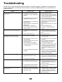
*Refer to T roubleshooting ( page 20 ) for more
information.
Important: The battery can be left on the charger
for short periods between uses.
If the battery will not be used for longer periods,
remove the battery from the charger; refer to
Storage ( page 19 ) .
16

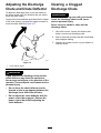
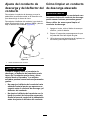
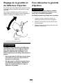
Adjusting the Discharge
Chute and Chute Deector
T o adjust the discharge chute, move the handle on
the chute-control rod in the direction that you wish to
direct the snow stream.
T o adjust the chute deector (and therefore the height
of the snow stream), squeeze the trigger and raise or
lower the chute deector ( Figure 16 ).
g318452
Figure 16
1. Chute deector trigger
W ARNING
A gap between the discharge chute and the
chute deector may allow the machine to
throw snow and objects in the direction of the
operator . Thrown objects could cause serious
personal injury .
• Do not force the chute deector too far
forward so that a gap appears between the
discharge chute and chute deector .
• Do not adjust the chute deector with the
power control bar engaged. Release the
power control bar before adjusting the
chute deector .
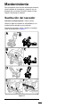
Clearing a Clogged
Discharge Chute
W ARNING
Contacting a rotating rotor with your hands
inside the discharge chute could cause
serious personal injury .
Never use your hands to clean out the
discharge chute.
1. Shut of f the motor , remove the electric-start
button, and remove the battery pack.
2. W ait 10 seconds to ensure that the rotor blades
have stopped rotating.
3. Always use a clean-out tool, not your hands, to
clear the chute.
17

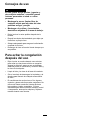
Operating T ips
W ARNING
The rotor can throw stones, toys, and other
foreign objects and cause serious personal
injury to you or bystanders.
• Keep the area to be cleared free of all
objects that the rotor blades could pick up
and throw .
• Keep all children and pets away from the
area of operation.
•Remove the snow as soon as possible after it falls.
•Push the machine forward, but allow it to work at
its own pace.
•Overlap each swath to ensure complete snow
removal.
•Discharge the snow downwind whenever possible.
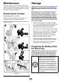
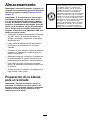
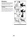
Preventing Freeze-up after
Use
•Let the motor run for a few minutes to prevent
moving parts from freezing. Shut of f the machine,
wait for all moving parts to stop, and remove ice
and snow from the machine.
•Clean of f any snow and ice from the base of the
chute.
•Rotate the discharge chute left and right to free
it from any ice buildup.
•In snowy and cold conditions, some controls and
moving parts may freeze. Do not use excessive
force when trying to operate frozen controls. If you
have dif culty operating any control or part, start
the machine and let it run for a few minutes.
18
La page est en cours de chargement...
La page est en cours de chargement...
La page est en cours de chargement...
La page est en cours de chargement...
La page est en cours de chargement...
La page est en cours de chargement...
La page est en cours de chargement...
La page est en cours de chargement...
La page est en cours de chargement...
La page est en cours de chargement...
La page est en cours de chargement...
La page est en cours de chargement...
La page est en cours de chargement...
La page est en cours de chargement...
La page est en cours de chargement...
La page est en cours de chargement...
La page est en cours de chargement...
La page est en cours de chargement...
La page est en cours de chargement...
La page est en cours de chargement...
La page est en cours de chargement...
La page est en cours de chargement...
La page est en cours de chargement...
La page est en cours de chargement...
La page est en cours de chargement...
La page est en cours de chargement...
La page est en cours de chargement...
La page est en cours de chargement...
La page est en cours de chargement...
La page est en cours de chargement...
La page est en cours de chargement...
La page est en cours de chargement...
La page est en cours de chargement...
La page est en cours de chargement...
La page est en cours de chargement...
La page est en cours de chargement...
La page est en cours de chargement...
La page est en cours de chargement...
La page est en cours de chargement...
La page est en cours de chargement...
La page est en cours de chargement...
La page est en cours de chargement...
La page est en cours de chargement...
La page est en cours de chargement...
La page est en cours de chargement...
La page est en cours de chargement...
La page est en cours de chargement...
La page est en cours de chargement...
La page est en cours de chargement...
La page est en cours de chargement...
La page est en cours de chargement...
La page est en cours de chargement...
La page est en cours de chargement...
La page est en cours de chargement...
La page est en cours de chargement...
La page est en cours de chargement...
-
 1
1
-
 2
2
-
 3
3
-
 4
4
-
 5
5
-
 6
6
-
 7
7
-
 8
8
-
 9
9
-
 10
10
-
 11
11
-
 12
12
-
 13
13
-
 14
14
-
 15
15
-
 16
16
-
 17
17
-
 18
18
-
 19
19
-
 20
20
-
 21
21
-
 22
22
-
 23
23
-
 24
24
-
 25
25
-
 26
26
-
 27
27
-
 28
28
-
 29
29
-
 30
30
-
 31
31
-
 32
32
-
 33
33
-
 34
34
-
 35
35
-
 36
36
-
 37
37
-
 38
38
-
 39
39
-
 40
40
-
 41
41
-
 42
42
-
 43
43
-
 44
44
-
 45
45
-
 46
46
-
 47
47
-
 48
48
-
 49
49
-
 50
50
-
 51
51
-
 52
52
-
 53
53
-
 54
54
-
 55
55
-
 56
56
-
 57
57
-
 58
58
-
 59
59
-
 60
60
-
 61
61
-
 62
62
-
 63
63
-
 64
64
-
 65
65
-
 66
66
-
 67
67
-
 68
68
-
 69
69
-
 70
70
-
 71
71
-
 72
72
-
 73
73
-
 74
74
-
 75
75
-
 76
76


