MRCOOL GeoCool Install Manual
- Catégorie
- Climatiseurs split-system
- Taper
- Install Manual

30

Geocool® - All rights reserved
Contact Information:
Geocool
48 Remington Way
Hickory, Ky 42051
www.geo.cool
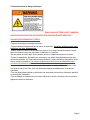
DO NOT install, operate, or maintain this equipment before carefully reading the instruction
manual.
Additional copies of the manual are available from the installing dealer or from Geocool.
Save the manual and any other operating instructions for yourself and any future owners of this
equipment.
A trained Geocool installer must perform all installation practices.
A licensed refrigeration technician must perform all refrigeration repairs / modifications.
Geocool must approve all service repairs if system is covered under manufacturer warranty.
Unless otherwise noted in the terms outlined in the following warranty, you must register
your product at one of the following links to receive the additional 5 years of GeoCool
product warranty:
English: http://geo.cool/your-warranty/residential/geocool-warranty-reg.html
Espanol: http://geo.cool/your-warranty/residential/spanish/geocool-warranty-reg.html

GeoCool LIMITED WARRANTY STATEMENT
GeoCool distributor (hereinafter “Company”) warrants this product against failure due to defect in materials or workmanship
under normal use and maintenance as follows. All warranty periods begin on the date of purchase. If the date cannot be
verified, the warranty period begins one hundred twenty (120) days from date of manufacture. If a part fails due to defect during
the applicable warranty period Company will provide a new or re-manufactured part, at Company’s option, to replace the failed
defective part at no charge for the part. This limited warranty is subject to all provisions, conditions, limitations and exclusions
listed below.
GeoCool provides a warranty period of five (5) years on the compressor and five (5) years on all parts to the original end user. An
additional five (5) years on all parts is provided to the original end user when the product is registered online within 60 days of
installation by a professional installer.
Limited warranty applies only to systems that are properly installed by a state certified or licensed HVAC contractor, under
applicable local and state law in accordance with all applicable building codes and permits; GeoCool installation and operation
instructions and good trade practices.
Warranty applies only to products remaining in their original location.
Defective parts must be returned to the distributor through a registered servicing dealer for credit.
LIMITATIONS OF WARRANTIES: ALL IMPLIED WARRANTIES AND/OR CONDITIONS (INCLUDING IMPLIED WARRANTIES OR
CONDITIONS OF MERCHANT-ABILITY AND FITNESS FOR A PARTICULAR USE OR PURPOSE) ARE LIMITED TO THE DURATION OF
THIS LIMITED WARRANTY, SOME STATES OR PROVINCES DO NOT ALLOW LIMITATIONS ON HOW LONG AN IMPLIED WARRANTY
OR CONDITION LASTS, SO THE ABOVE MAY NOT APPLY TO YOU. THE EXPRESS WARRANTIES MADE IN THIS WARRANTY ARE
EXCLUSIVE AND MAY NOT BE ALTERED, ENLARGED, OR CHANGED BY ANY DISTRIBUTOR, DEALER, OR OTHER PERSON,
WHATSOEVER. THIS WARRANTY DOES NOT COVER:
1. Labor or other costs incurred for diagnosing, repairing, removing, installing, shipping, servicing or handling of either
defective parts, or replacement parts, or new units.
2. Products cleaning required prior to warranty service and repair.
3. Normal maintenance as outlined in the installation and servicing instructions or Owner’s Manual, including filter cleaning
and/or replacement and lubrication.
4. Failure, damage or repairs due to faulty installation, misapplication, abuse, improper servicing, unauthorized alteration or
interruption of electrical service.
5. Failure to start due to voltage conditions, blown fuses, open circuit breakers, or damages due to the inadequacy or
interruption of electrical service.
6. Failure or damage due to floods, winds, fires, lighting, accidents, corrosive environments (rust, etc.) or other conditions
beyond the control of the Company.
7. Failure or damage of coils or piping due to corrosion on installations within one (1) miles of sea coast or corrosive body.
8. Parts not supplied or designated by Company, or damages resulting from their use.
9. Products installed outside the continental USA and Canada.
10. Electricity or fuel costs, or increases in electricity or fuel costs from any reason whatsoever, including additional or
unusual use of supplemental electric heat.
11. Any cost to replace, refill or dispose of refrigerant, including the cost of refrigerant.
12. Shipping damage or damage as a result of transporting the unit.
13. System accessories are not covered.
14. Any special, indirect or consequential property or commercial damage of any nature whatsoever. Some states or
provinces do not allow the exclusion of incidental or consequential damages, so the above limitation may not apply to you.
This warranty gives you specific legal rights, and you may also have other rights which vary from state to state or province to
province. California and Quebec residents do not need to register the product in order to get all of the rights and remedies of
registered owners under this warranty.
For any questions call 855-GEO-COOL (855-436-2665) or visit our website at Geo.Cool

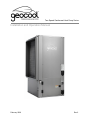
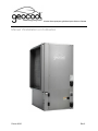
Two-Speed Geothermal Heat Pump Series
Installation and Operation Manual
February 2020 Rev.2

Page 2

Table of Contents
4
5
6
8
9
10
11
12
14
17
18
19
21
25
26
27
29
Contact Information
Model Nomenclature
Technical Data
Transportation and Storage
Electrical Hazards
System Installation
Ductwork Considerations
Ground Loop System
Open Loop System
Condensate Considerations
DHW PLumbing
High and Low Voltage Wiring
Dallas Microprocessor
DEC Star Blower
Start Up Procedures
Preventive Maintenance
Troubleshooting
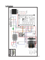
Wiring Diagram
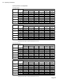
Operating Parameters
31
Page 3
32

Geocool - All rights reserved
Geocool® has compiled this manual with care; however Geocool does not warrant that the
information in this manual is free of errors. Geocool reserves the right to change any portion of
this manual without notice. The appearance of any technical data or editorial material in this
manual does not constitute endorsement, warranty, or guarantee by Geocool of any product,
service, process, procedure, design, or the like. The user assumes the entire risk of the use of
any information in this manual.
Contact Information:
Geocool
48 Remington Way
Hickory, Ky 42051
www.geo.cool
DO NOT install, operate, or maintain this equipment before carefully reading this
instruction manual.
Additional copies of this manual are available from the installing dealer or from Geocool.
Save the manual and any other operating instructions for yourself and any future owners
of this equipment.
A trained Geocool installer must perform all installation practices.
A licensed refrigeration technician must perform all refrigeration repairs / modifications.
Geocool must approve all service repairs if system is covered under manufacturer
warranty
Unless otherwise noted in the terms outlined in the warranty, you must register your
product at one of the following links to receive the additional 5 years of Geocool product
warranty:
English: http://geo.cool/your-warranty/residential/geocool-warranty-reg.html
Espanol: http://geo.cool/your-warranty/residential/spanish/geocool-warranty-reg.html
Page 4

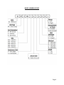
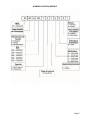
MODEL NOMENCLATURE
Page 5

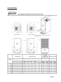
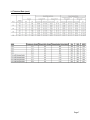
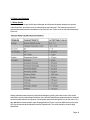
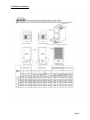
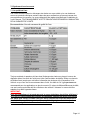
1.0 Technical Data
Page 6

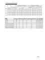
1.0 Technical Data (cont.)
Page 7

2.0 Transportation & Storage
Move and store units in an upright position. Do not stack units. Inspect shipment for shipping
damage and check packing slips for accuracy. Any equipment or cartons in question should be
removed from the packing and physically inspected. If any damage is detected, the carrier
should make a note on the delivery slip acknowledging the damage. In some cases smaller
items like thermostat or temperature sensors will be packed and shipped inside the unit.
During freezing conditions special consideration should be made to prevent unit
damage. If a unit is taken to the job site or put in storage, antifreeze will need to be
pumped into the water coils to prevent freezing. Failure to do this will void the warranty.
Page 8

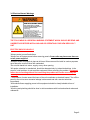
3.0 Electrical Hazard Warnings
THE FOLLOWING IS A GENERAL WARNING STATEMENT WHICH SHOULD BE READ AND
UNDERSTOOD BEFORE INSTALLING AND OR OPERATING YOUR NEW GEOCOOL™
UNIT
ELECTRIC SHOCK CAN KILL!!
*Always protect yourself and others.
*Always turn off system power before removing panels. Some units may have more than one
or two power supplies.
*Keep all covers and panels in place at all times. When removed for install or service purposes
never leave the cover off when left unattended.
*Do not stick hands into return, supply, or any other opening.
*All repairs, electrical or mechanical, should be attempted only by trained technicians. In the
event of a unit problem, do not reset the equipment before correcting the problem. Equipment
failure due to resetting without first correcting the problem will not be covered by the
warranty.
*The presence of water around the base of the unit constitutes an electrical hazard. Turn off the
power to the unit as soon as water leakage is discovered and call a service technician
immediately.
*All breakers/fuses supplying power to this equipment should be clearly labeled at time of
installation.
*All wiring and plumbing should be done in strict accordance with local and national codes and
ordinances
Page 9

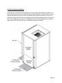
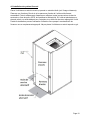
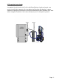
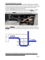
4.0 Geocool System Installation
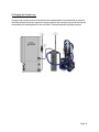
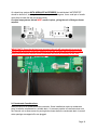
Locate the unit in an indoor area that allows for easy servicing (see image below). Make sure
that the air filter access and unit access panels are easily accessible. Provide sufficient room to
make all ground loop, well water, DHW, condensate, and electrical connections. If the unit is
placed in a closet, make provision for adequate service access and proper return air flow to the
unit. Some installations may require a condensate pump to take the condensate to a suitable
drain location. Do not locate the unit in an area that is subject to freezing.
Page 10

5.0 Ductwork Considerations
Important Note: If ductwork i s i nstalled i n an attic area, the ductwork needs to be built “low
profile” and l aid directly on the ceiling j oist (code permitting). After being i nstalled and wrapped
in i nsulation, i t i s recommended the ductwork be covered with six to eight i nches of cellulose. If
the attic ductwork i s not covered with cellulose i t can l ose a significant amount of i ts heating and
cooling capacity i nto the attic area!! Ductwork that i s i nadequately insulated will cause poor system
performance and customer dissatisfaction.
In the USA, ductwork sizing methods should follow ACCA “Manual D” recommendations. Install
ductwork within the conditioned space of the building to minimize duct heat l oss or gain,
wherever possible.
To minimize air velocity noise transferring to the air supply grills, a flex duct should be i nstalled
from the supply grill six feet back.
Ductwork should be designed to handle the CFM delivery for the unit while running i n High
Speed. Supply duct should be based on .08 i nches of pressure drop per 100 feet. Return duct
should be based on .05 i nches of pressure drop per 100 feet.
Note: Always check register CFM requirements against register manufacturer’s data for register
performance. It i s extremely i mportant to ensure that duct system for return airflow i s NOT
undersized. Undersized return air ductwork can cause poor system performance and i n some
cases can cause the blower to “pulse”. Furthermore, i t i s also i mportant to provide adequate sized
supply air plenums and ductwork. Make all turns as smooth as possible avoiding any restrictions.
For residential design the target static pressure should not be greater than 0.3 inches.
Caution: Observe the location where your ductwork is being attached to the unit. Ensure
that drilling and screws do not penetrate and damage the air coil.
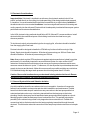
5.1 Geocool System Noise and Vibration Isolation
A quality i nstallation should be one where noise i s not a complaint. A number of i nexpensive
features can be added to reduce noise and also aid i n i nstallation and maintenance. Flexible
hose kits to the hot water l oop will make for an easy connection to the heat pump and the hot
water tank and also reduce any noise being transmitted from the heat pump to the i ndoor
plumbing. Next the heat pump and all associated water pumps should be i nstalled on a shock-
absorbing pad to i solate the heat pump from a hard surface floor. This pad will help stop the
possibility of the cabinet being rusted out by trapped moisture under the unit. Flexible duct
connections help to eliminate noise from the heat pump being transmitted through the metal
ductwork. This collar also makes the connection of the heat pump to the ductwork a much simpler
task.
Page 11

5.2 Air Filtering
To maintain good i ndoor air quality i n a tight building, the air distribution system should have a
high-efficiency air filter. To ensure proper unit operation, be sure to i nform the building owner of
the i mportance of proper maintenance and the maintenance schedule for checking/changing the
filter i nstalled. Most air filters require monthly attention.
5.3 Construction / Remodeling
The Geocool unit should NEVER be run during any kind of construction or remodeling that
would allow drywall, hard wood, or any kind of dust to be pulled i n the system. Even with extra
filtering dust particles can accumulate i n the duct system causing unwanted dust for years to
come. It can also cause air coil clogging, condensate drain clogging, blower dust accumulation
and many other problems to the system. Running the system during construction / remodeling
will VOID the system warranty
6.0 The Ground Loop System
6.1 Closed Loop Systems Plumbing
IMPORTANT! Do NOT use PVC or CPVC piping on any connections to your Geocool unit. The
only exception where PVC or CPVC piping may be used i s on the condensate l ines.
Closed l oop systems will require a minimum of 3 G.P.M. per ton i f the ground l oop i s designed
to maintain a l oop temperature above 32ºF and below 90ºF. If design temperatures are outside
of these temperatures more flow will be needed.
On residential units, a pump i s typically required for each unit. The l oop pump requirement will
depend upon the l oop design for a given application. The ground l oop piping system must
provide suitable access for purging the outside l oop and require i solation valves for purging the
inside plumbing i ncluding the unit. To properly purge a closed l oop system, a minimum velocity
of 2 feet per second i n every branch of the ground l oop must be achieved. The purge ports can
also be used for anti-freeze charging.
IMPORTANT NOTICE: UNITS THAT UTILIZE GROUND LOOPS MUST MAINTAIN A MINIMUM
OF 20% METHANOL OR 25% PROPYLENE GLYCOL AS AN ANTIFREEZE SOLUTION IN THE
UNIT AND GROUND LOOP AT ALL TIMES. FAILURE TO DO SO WILL FREEZE THE SYSTEM
AND CAUSE SEVERE DAMAGE TO THE UNIT. DAMAGE TO THE UNIT CAUSED BY THE
FAILURE TO MAINTAIN PROPER ANTIFREEZE LEVELS IS NOT COVERED UNDER THE
WARRANTY.
Page 12

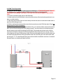
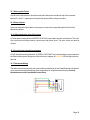
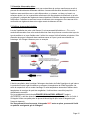
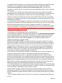
6.2 Purging the Closed Loop
Purging of the closed l oop and unit should only be completed after i t has passed the air pressure
check and all l eaks have been repaired. Purging requires a high velocity pump and should only be
completed by the i nstalling dealer or sub-contractor. See drawing below for piping example.
Page 13

7.0 Open Loop Systems
7.1 Water Quality
Geocool units use a cupro nickel heat exchanger which has an i ncreased resistance to ground
water chemicals , which are known to cause build up and corrosion. The water source must be
tested and treated before the i nstallation of the Geocool unit. Failure to do so will void the warranty
of the unit.
Always maintain water pressure i n the heat exchanger by placing the water control valve at the
outlet of the unit to prevent deposit buildup. Use a closed, bladder-type expansion tank to minimize
mineral formation due to air exposure. Insure proper water flow through the unit. A flow rate of 2-3
gpm per ton i s recommended i n open l oop applications. Due to only minor differences i n flow rate,
only one motorized valve should be used on 2 speed units. The valve should be sized for high
speed flow.
Page 14

IMPORTANT:
On installations where the groundwater temperature is expected to fall below 50°F during
any part of the heating season, perform a calculation to anticipate higher flow rate
requirements. A higher water flow rate results in a lower temperature drop through the
liquid to refrigerant heat exchanger. This prevents the Freeze protection/low limit from
activating unnecessarily.
7.2 Discharge Water Line
Discharge water from the unit is not contaminated in any manner and can be disposed of in
various ways. Discharge water should run outside with no restrictions to a discharge well, creek,
pond, storm drain, etc. Discharge piping must be prepared in a manner that will not freeze. Most
local codes forbid the use of sanitary sewer for disposal. Consult your local building and zoning
departments to assure compliance in your area prior to discharging water.
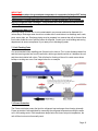
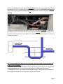
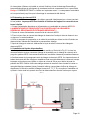
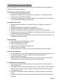
7.3 Coil Flushing Ports
It is recommended when installing your Geocool unit to have a “Tee” on the discharge water line
and the incoming water line from the well with a boiler type drain/hose bib on it between the unit
and the main isolation ball valves. This will allow for flushing of the coil in certain areas where
buildup or scaling can occur. See image below for an example.
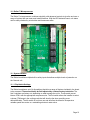
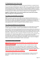
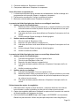
7.4 Freeze Protection
The Freeze stat helps protect the liquid to refrigerant heat exchanger from freezing internally.
Freeze protection is accomplished by measuring the refrigerant temperature exiting the water
coil in the heating mode. If this temperature drops below the freeze set point temperature, the
unit will then lock out until manually reset.
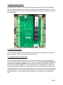
Page 15

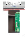
On closed loop systems WITH ADEQUATE ANTIFREEZE, the tab labeled “ANTIFREEZE”
should be broken off, lowering the unit freeze setpoint to 20 degrees. Use a small pair of needle
nose pliers to break the tab (see image below).
On open loop systems, the tab MUST remain in place, giving the unit a 38 degree freeze
setpoint.
IMPORTANT!!! Once the tab has been removed, the unit will permanently be set to 20
degrees and cannot be reversed!! Removal of the tab on open loop systems or closed
loop systems without minimal freeze protection will VOID all warranty on the unit!
8.0 Condensate Considerations
Make provision for a condensate drain connection. Some installations require a condensate
pump to take the condensate to a suitable drain. It’s common practice to install extra tees near
the Geocool unit to allow access for pouring drain cleaner down the condensate drain. Insure all
extra openings are capped off or are plugged.
Page 16

All Geocool vertical units have P-traps built i nternally withi n the units (see i mage below). These
units require a vent to be i nstalled downstream and outside of the unit. Installation of a second P-
Trap is not necessary and if installed, will not allow the unit's condensate pan to drain
properly,
All Geocool Horizontal units are low profile. Due to this, they require standard P-Traps which
are vented on the leaving water side and located directly outside the unit (see image below).
Horizontal cabinets will need to be installed on a platform if not hanging in the air in order for a
P-trap to be installed.
Never tie the condensate drain and the discharge water line together due to the potential
for severe water damage.
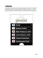
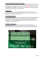
A float switch i s factory i nstalled i nside the Geocool® drain pan . When this switch is triggered by
condensate backing up, will shut down the compressor and a RED status l ight l abeled
“ CONDENSATE FAULT ” will show up on the front panel display. The compressor will remain off
and the l ight i lluminated until the condensate clog has been cleared.
Page 17
La page charge ...
La page charge ...
La page charge ...
La page charge ...
La page charge ...
La page charge ...
La page charge ...
La page charge ...
La page charge ...
La page charge ...
La page charge ...
La page charge ...
La page charge ...
La page charge ...
La page charge ...
La page charge ...
La page charge ...
La page charge ...
La page charge ...
La page charge ...
La page charge ...
La page charge ...
La page charge ...
La page charge ...
La page charge ...
La page charge ...
La page charge ...
La page charge ...
La page charge ...
La page charge ...
La page charge ...
La page charge ...
La page charge ...
La page charge ...
La page charge ...
La page charge ...
La page charge ...
La page charge ...
La page charge ...
La page charge ...
La page charge ...
La page charge ...
La page charge ...
La page charge ...
La page charge ...
La page charge ...
La page charge ...
-
 1
1
-
 2
2
-
 3
3
-
 4
4
-
 5
5
-
 6
6
-
 7
7
-
 8
8
-
 9
9
-
 10
10
-
 11
11
-
 12
12
-
 13
13
-
 14
14
-
 15
15
-
 16
16
-
 17
17
-
 18
18
-
 19
19
-
 20
20
-
 21
21
-
 22
22
-
 23
23
-
 24
24
-
 25
25
-
 26
26
-
 27
27
-
 28
28
-
 29
29
-
 30
30
-
 31
31
-
 32
32
-
 33
33
-
 34
34
-
 35
35
-
 36
36
-
 37
37
-
 38
38
-
 39
39
-
 40
40
-
 41
41
-
 42
42
-
 43
43
-
 44
44
-
 45
45
-
 46
46
-
 47
47
-
 48
48
-
 49
49
-
 50
50
-
 51
51
-
 52
52
-
 53
53
-
 54
54
-
 55
55
-
 56
56
-
 57
57
-
 58
58
-
 59
59
-
 60
60
-
 61
61
-
 62
62
-
 63
63
-
 64
64
-
 65
65
-
 66
66
-
 67
67


MRCOOL GeoCool Install Manual
- Catégorie
- Climatiseurs split-system
- Taper
- Install Manual
dans d''autres langues
- English: MRCOOL GeoCool
