Skil PED0900 PWR Core 40 9 in. Edger Attachment Le manuel du propriétaire
- Catégorie
- Outils électroportatifs
- Taper
- Le manuel du propriétaire

WARNING: To reduce the risk of injury, the user must read and understand the
Owner’s Manual before using this product. Save these instructions for future reference.
AVERTISSEMENT : Afin de réduire les risques de blessure, l’utilisateur doit lire et
comprendre le guide d’utilisation avant d’utiliser cet article. Conservez le présent guide afin
de pouvoir le consulter ultérieurement.
ADVERTENCIA : Para reducir el riesgo de lesiones, el usuario debe leer y comprender
el Manual del operador antes de utilizar este producto. Guarde estas instrucciones para
consultarlas en caso sea necesario.
Owner’s Manual
Guide d’utilisation
Manual del propietario
For Customer Service
Pour le service à la clientèle
Servicio al cliente 1-877-SKIL-999 OR www.skil.com
9" Edger Attachment
Attachement de coupe-bordure de 9 po
Aditamento de bordeadora de 9 pulgadas
Model/ Modelo/ Modèle: PED0900

2
TABLE OF CONTENTS
Important Safety Instructions ....................................3-4
Symbols .....................................................5-8
Get To Know Your Edger Attachment ...............................9
Specications ..................................................9
Assembly .....................................................11
Operating Instructions .......................................12-14
Maintenance ................................................ 15-17
Troubleshooting ...............................................18
Limited Warranty of SKIL Consumer Tools ..........................19

3
IMPORTANT SAFETY INSTRUCTIONS
General power tool safety warnings
WARNING Read all safety warnings, instructions, illustrations and specifications
provided with this power tool. Failure to follow all instructions listed
below may result in electric shock, re and/or serious injury.
SAVE ALL WARNINGS AND INSTRUCTIONS FOR FUTURE REFERENCE.
The term “power tool” in the warnings refers to your mains-operated (corded) power tool or
battery-operated (cordless) power tool.
Wear appropriate personal hearing protection during use. Under some conditions and du-
rations of use, noise from this product may contribute to hearing loss.
Avoid Dangerous Environments – Don’t use appliances in damp or wet locations.
Don’t Use In Rain.
Keep Children Away - All visitors should be kept at a distance away from work area.
Dress Properly - Do not wear loose clothing or jewelry. They can be caught in moving parts.
Use of rubber gloves and substantial footwear is recommended when working outdoors. Wear
protective hair covering to contain long hair.
Use Safety Glasses. Always use face or dust mask if operation is dusty.
Use Right Appliance - Do not use appliance for any job except that for which it is intended.
Don’t Force Appliance - It will do the job better and with less likelihood of a risk of injury at
the rate for which it was designed.
Don’t Overreach - Keep proper footing and balance at all times.
Stay Alert - Watch what you are doing. Use common sense. Do not operate the edger when
you are tired or while under the inuence of alcohol or drugs.
Keep guards in place and in working order.
Keep blades sharp. Replace dull or worn blade; do not attempt to sharpen.
Keep hands and feet away from the cutting area.
Never stand or have any part of your body in line with the path of the edger blade.
Store Idle Appliances Indoors - When not in use, appliances should be stored indoors in a
dry and high or locked-up place with the battery pack removed and out of reach of children.
Maintain Appliance with Care - Keep cutting edge sharp and clean for best performance and
to reduce the risk of injury. Follow instructions for lubricating and changing accessories. Keep
handles dry, clean, and free from oil and grease.
Check Damaged Parts - Before further use of the product, a guard or other part that is dam-
aged should be carefully checked to determine that it will operate properly and perform its
intended function. Check for alignment of moving parts, binding of moving parts, breakage of
parts, mounting, and any other condition that may affect its operation. A guard or other part
that is damaged should be properly repaired or replaced by an authorized service center un-
less indicated elsewhere in this manual.
Clear the area to be cut before each use. Remove all objects such as rocks, broken glass,
nails, wire, or string that can be thrown or become entangled in the cutting attachment.
Always hold the edger firmly, with both hands on the handles, while operating. Wrap
your fingers and thumbs around the handles.
Avoid Accidental Starting - Don’t carry the edger with your nger on the trigger.
Do not operate the edger in gaseous or explosive atmospheres. Motors in these applianc-
es normally spark, and the sparks might ignite fumes.

4
Do not use the edger on or near graveled surfaces.
Damage to edger - If you strike a foreign object with the edger, stop the tool immediately,
check for damage and have any damage repaired before further operation is attempted. Do
not operate with a broken guard or blade.
Replace a cracked, damaged or worn-out blade immediately, even if damage is limited
to superficial cracks. Such attachments may shatter at high speed and cause serious or fatal
injury.
Do not charge the battery pack in rain, or in wet locations.
Replacement Parts - When servicing, use only identical replacement parts. Use of any other
accessory or attachment may increase the risk of injury.
Battery tools do not have to be plugged into an electrical outlet; therefore, they are
always in operating condition. Be aware of possible hazards even when the tool is not
operating. Take care when performing maintenance or service.
Remove or disconnect battery pack before servicing, cleaning or removing material
from the product.
Do not wash with a hose; avoid getting water in motor and electrical connections.
Do not incinerate the appliance even if it is severely damaged. The batteries can
explode in a fire.
If situations occur that are not covered in this manual, use care and good judgment.
Contact the Customer Service Center for assistance.
Save these instructions. Refer to them frequently and use them to instruct others who may
use this tool. If you lend this tool to someone else, also lend these instructions to them to
prevent misuse of the product and possible injury.
Use only with 40V Power Head PH0040.
NOTE: SEE YOUR SKIL PH0040 POWER HEAD OWNER’S MANUAL FOR ADDITIONAL
SPECIFIC SAFETY RULES.
SAVE THESE INSTRUCTIONS!

5
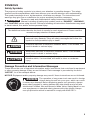
SYMBOLS
Safety Symbols
The purpose of safety symbols is to attract your attention to possible dangers. The safety
symbols and the explanations with them deserve your careful attention and understanding.
The symbol warnings do not, by themselves, eliminate any danger. The instructions and
warnings they give are no substitutes for proper accident prevention measures.
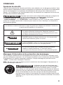
WARNING Be sure to read and understand all safety instructions in this Owner's
Manual, including all safety alert symbols such as “DANGER”, “WARNING”,
and “CAUTION” before using this tool. Failure to following all instructions listed below may result
in electric shock, re, and/or serious personal injury.
The denitions below describe the level of severity for each signal word. Please read the
manual and pay attention to these symbols.
This is the safety alert symbol. It is used to alert you to potential
personal injury hazards. Obey all safety messages that follow this
symbol to avoid possible injury or death.
DANGER DANGER indicates a hazardous situation which, if not avoided, will
result in death or serious injury.
WARNING WARNING indicates a hazardous situation which, if not avoided,
could result in death or serious injury.
CAUTION CAUTION, used with the safety alert symbol, indicates a hazardous
situation which, if not avoided, will result in minor or moderate
injury.
Damage Prevention and Information Messages
These inform the user of important information and/or instructions that could lead to equipment
or other property damage if they are not followed. Each message is preceded by the word
“NOTICE”, as in the example below:
NOTICE: Equipment and/or property damage may result if these instructions are not followed.
WARNING The operation of any power tools can result in foreign
objects being thrown into your eyes, which can result
in severe eye damage. Before beginning power tool operation, always
wear safety goggles or safety glasses with side shields and a full face
shield when needed. We recommend a Wide Vision Safety Mask for use
over eyeglasses or standard safety glasses with side shields. Always
use eye protection which is marked to comply with ANSI Z87.1.

6
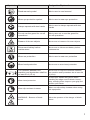
SYMBOLS (CONTINUED)
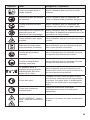
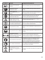
IMPORTANT: Some of the following symbols may be used on your tool. Please study them
and learn their meaning. Proper interpretation of these symbols will allow you to operate the
tool better and more safely.
Symbol Name Designation/Explanation
V Volts Voltage (potential)
AAmperes Current
Hz Hertz Frequency (cycles per second)
W Watt Power
kg Kilograms Weight
min Minutes Time
s Seconds Time
Wh Watt-hours Battery capacity
Ah Ampere-hours Battery capacity
øDiameter Size of drill bits, grinding wheels, etc.
n0Maximum speed Maximum rotational speed
…/min Revolutions or reciprocations per
minute (rpm)
Revolutions, strokes, surface speed,
orbits, etc. per minute
IPX4 Ingress protection degree Protection from splashing water
0Off position Zero speed, zero torque...
1,2,3,…
Ⅰ,Ⅱ,Ⅲ, Selector settings Speed, torque, or position settings.
Higher number means greater speed
Innitely variable selector with off Speed is increasing from 0 setting
Arrow Action in the direction of arrow
Alternating current (AC) Type or a characteristic of current
Direct current (DC) Type or a characteristic of current
Alternating or direct current
(AC / DC) Type or a characteristic of current
Class II tool Designates Double Insulated Construction
tools.
Earthing terminal Grounding terminal
Li-ion RBRC seal Designates Li-ion battery recycling
program

7
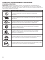
Symbol Name Designation/Explanation
Read manual symbol Alerts user to read manual
Wear eye protection symbol Alerts user to wear eye protection
Always operate with two hands Alerts user to always operate with two
hands
Do not use the guard for cut-off
operations
Alerts user not to use the guard for
cut-off operations
Beware of thrown objects Alerts user to beware of thrown objects
Disconnect battery before
maintenance
Alerts user to disconnect battery before
maintenance
Wear ear protection Alerts user to wear ear protection
Wear head protection Alerts user to wear head protection
The distance between the
machine and bystanders shall be
at least 50 ft (15 m)
Alerts user to keep the distance between
the machine and bystanders be at least 50
ft (15 m)
Wear hand protection
Protect your hands with gloves when
handling the edger and its blade. Heavy-
duty, nonslip gloves improve your grip and
protect your hands
Wear slip-resistant footwear Wear non-slip safety footwear when using
this equipment
WARNING – Beware of blade
thrust
Warn the operator of the danger of blade
thrust

8
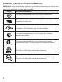
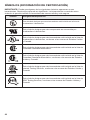
SYMBOLS (CERTIFICATION INFORMATION)
IMPORTANT: Some of the following symbols for certication information may be used on your
tool. Please study them and learn their meaning. Proper interpretation of these symbols will
allow you to operate the tool better and more safely.
Symbol Designation/Explanation
This symbol designates that this tool is listed by Underwriters
Laboratories.
This symbol designates that this component is recognized by
Underwriters Laboratories.
This symbol designates that this tool is listed by Underwriters
Laboratories, to United States and Canadian Standards.
This symbol designates that this tool is listed by the Canadian
Standards Association.
This symbol designates that this tool is listed by the Canadian
Standards Association, to United States and Canadian Standards.
This symbol designates that this tool is listed by the Intertek Testing
Services, to United States and Canadian Standards.
This symbol designates that this tool is listed by the SGS Testing
Services, to United States and Canadian Standards.

9
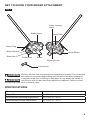
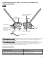
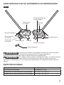
GET TO KNOW YOUR EDGER ATTACHMENT
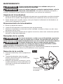
Fig. 1
Blade Guard
Depth Locking
Knob
Guide Plate
Guide Wheel
Sealing Screw
Guide Plate
Blade Nut
Blade Retainer
Debris Flap
Blade
Hex wrench
WARNING Remove the tool from the package and examine it carefully. Do not discard
the carton or any packaging material until all parts have been examined.
WARNING If any part of the tool is missing or damaged, do not attach the battery to
use the tool until the part has been repaired or replaced. Failure to heed
this warning could result in serious injury.
SPECIFICATIONS
Blade length 9 In (23 cm)
Edging Depth 3 In (76 mm)
Recommended operating temperature 32 - 104°F (0 - 40°C)
Recommended storage temperature 32 - 104°F (0 - 40°C)

10
Blade
Metal cutting blade for cutting weeds and soft green plants.
Blade Guard
Reduces the risk of injury from foreign objects ung backwards toward the operator by the
cutting blade and from contact with the cutting blade.
Debris Flap
Reduces the risk of injury from foreign objects ung back towards the operator by the cutting
blade.
Depth Locking Knob and Guide Plate
Adjust the depth of cut.
Guide wheel
Rolls on ground and keeps edger blade at preset height for required depth of cut.

11
ASSEMBLY
WARNING To prevent accidental starting that could cause serious personal
injury, always remove the battery pack from the tool when assembling
parts, making adjustments, cleaning, or when not in use.
WARNING If any parts are damaged or missing, do not operate this product until
the parts are replaced. Use of this product with damaged or missing parts
could result in serious personal injury.
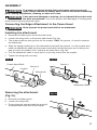
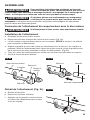
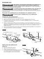
Connecting the Edger Attachment to the Power Head
WARNING Never operate the power head without an attachment.
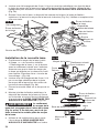
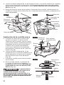
Installing the attachment
a. Remove the battery pack from the power head.
b. Loosen the wing knob on the power head shaft (Fig. 2a).
c. The power head has two grooves on the coupler, ONLY the groove 1 is used to connect
an attachment.
d. Align the spring-loaded pin on the attachment shaft with the groove 1 on the coupler and
push the attachment shaft into the power head shaft until the pin pops out of the groove
and you hear an audible “click” sound at the same time. (Fig. 2b).
e. Pull the attachment shaft to verify that it is securely locked into the coupler.
f. Tighten the wing knob securely.
Fig. 2a
Power-Head Shaft
Coupler
Groove 2
Groove 1
Wing Knob
Fig. 2b
Groove 1 Pin
Attachment Shaft
Removing the attachment
(Fig. 2c)
a. Remove the battery pack.
b. Loosen the wing knob.
c. Press down the spring-loaded pin and pull
the attachment shaft out of the coupler.
2
1
Fig. 2c
Pin

12
OPERATING INSTRUCTIONS
WARNING To reduce the risk of fire, personal injury, and product damage due to
a short circuit, never immerse your tool, battery pack, or charger in
fluid or allow a fluid to flow inside them. Corrosive or conductive uids, such as seawater,
certain industrial chemicals, and bleach or bleach-containing products, etc. can cause a short
circuit.
WARNING Do not use any attachments or accessories not recommended by the
manufacturer of this product. The use of attachments or accessories not
recommended can result in serious personal injury.
WARNING Do not attempt to modify this tool or the battery pack or create
accessories not recommended for use with this tool.
Any such
alteration or modication is misuse and could result in a hazardous condition leading to
possibly serious injury.
WARNING To prevent accidental starting that could cause serious personal
injury, always remove the battery pack from the tool when assembling
parts, making adjustments, cleaning, or when not in use.
WARNING Do not allow familiarity with this product to make you careless.
Remember that a careless fraction of a second is sufficient to inflict
serious injury.
WARNING Always wear eye protection with side shields marked to comply with
ANSI Z87.1, along with hearing protection. Failure to do so could
result in objects being thrown into your eyes and other possible serious injuries.
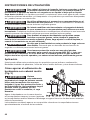
Application
You may use this product for the purposes listed below:
Edging around walkways, curbs, ower beds and other similar areas.
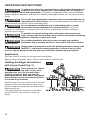
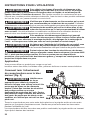
Holding the Edger Attachment
with Power Head (Fig. 3)
WARNING Dress properly to reduce
the risk of injury when
operating this tool. Do not wear loose
clothing or jewelry. Wear eye and ear/
hearing protection. Wear heavy, long pants,
boots and gloves. Do not wear short pants
or sandals or go barefoot.
Hold the edger with your right hand on the rear
handle and your left hand on the front-assist
handle. Keep a rm grip with both hands while
operating the tool.
The edger should be held at a comfortable
position with the rear handle at about hip
height.
Fig. 3

13
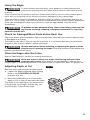
Using the Edger
WARNING To avoid serious personal injury, wear googles or safety glasses at all
times when operating this unit. Wear a face mask or dust mask in dusty
locations.
Clear the area to be cut before each use. Remove all objects, such as rocks, broken glass,
nails, wire, or string that can be thrown or become entangled in the cutting blade.
Clear the area of children, bystanders, and pets. Keep all children, bystanders and pets at
least 50 ft. (15 m) away. There still may be risk to bystanders from thrown objects; bystanders
should be encouraged to wear eye protection. If you are approached, stop the motor
immediately.
WARNING To prevent serious personal injury, remove the battery pack from the
tool before servicing, cleaning, changing attachments or removing
material from the unit.
Check for Damaged/Worn Parts before Each Use
Check the blade, guard and debris ap and replace any parts that are cracked, warped, bent,
or damaged in any away.
The blade on the side of the unit can dull over time. It is recommended that you periodically
sharpen it with a le or replace it with a new blade.
WARNING Always wear gloves when mounting or replacing the guard or when
sharpening or replacing the blade. Note the location of the blade and
protect your hand from injury.
Clean the Edger after Each Use
See the “Maintenance” section for cleaning instructions.
WARNING Never use water to clean your edger. Avoid using solvents when
cleaning plastic parts. Most plastics are susceptible to damage from
various types of commercial solvents. Use clean clothes to remove dirt, dust, oil, grease, etc.
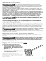
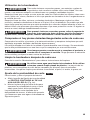
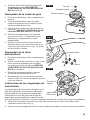
Adjusting Depth of Cut
Stop the motor and remove the battery pack.
a. Loosen the depth adjusting depth locking
knob in the COUNTERCLOCKWISE
direction (Fig. 4a).
b. Move the guide plate up to increase the
depth of cut or down to decrease the depth.
The depth of cut depends on the unevenness
of the ground, your height, and the way you
hold the edger. Follow these steps:
Fig. 4a

14
c. Adjust the guide plate so that the blade just
touches the ground or breaks the surface
of the soil (Fig. 4b).
d. Tighten the depth locking knob
CLOCKWISE securely.
e. Standing in the normal working position,
check the depth of cut again and correct it
if necessary.
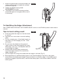
To Start/Stop the Edger Attachment
See “STARTING/STOPPING THE POWER HEAD” section in the PH0040 power head owner’s
manual.
Tips for best cutting result
a. Hold and guide the edger so that the blade
is vertical.
b. Operate at no more than a normal walking
pace.
c. Cut at a steady pace. If the blade begins to
bog down, you are edging too fast – slow
your pace.
d. Do not force the blade into the ground.
Light contact of the blade against the side-
walk edge, curb, etc. is acceptable and will
not damage the edger.
e. Always walk forward when cutting and
move the edger forward. Do not pull the
edger towards you.
f. Use the sight line to align the blade with the edge of the bed (Fig. 5).
g. Best appearance is obtained when grass is dry. Avoid edging in wet soil or wet grass
areas where the blade guard might clog and result in an uneven edge. If the blade guard
becomes clogged, stop the motor, remove the battery pack, and remove debris from the
blade guard.
Fig. 4b
Fig. 5
Sight line

15
MAINTENANCE
WARNING All maintenance should only be carried out by a qualified service
technician.
WARNING Before cleaning or performing any maintenance, remove battery from
the tool. For safe and proper operation, always keep the tool and its
ventilation slots clean.
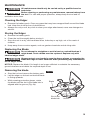
Cleaning the Edger
a. Remove the battery pack. Clear any grass that may have wrapped itself around the blade
hub. Keep the air vents free of obstructions.
b. Always use only a soft, dry cloth to clean your edger attachment; never use detergent or
alcohol.
Storing the Edger
a. Remove the battery pack.
b. Clean the tool thoroughly before storing it.
c. Store the unit in a dry, well-ventilated area, locked-up or up high, out of the reach of
children.
d. Keep away from corrosive agents, such as garden chemicals and de-icing salts.
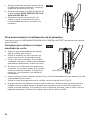
Replacing the Blade
WARNING Do not attempt to straighten or weld a bent or cracked blade as it
might break. Such a blade must be replaced. Replace only with
identical edger blade.
WARNING Always protect your hands by wearing heavy gloves or wrapping the
blade with rags or other materials when performing any maintenance
on the edger blade.
NOTICE: Replace the blade if its length is no longer sufcient to maintain the necessary
ground clearance and obtain the required depth of cut.
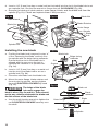
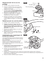
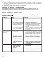
Removing the blade
a. Stop the tool and remove the battery pack.
b. Lay the edger on its back so that the blade
is facing upwards.
c. While wearing protective gloves, rotate
the blade until the slot in the blade hub is
aligned with the groove (Fig. 6a).
Fig. 6a
Blade
Groove
Slot in the
blade hub

16
d. Insert a 1/4” (6 mm) hex key or metal rod (not included) into the slot in the blade hub to act
as a spindle lock. Use the hex wrench to loosen the nut CLOCKWISE (Fig. 6b).
e. Remove the blade nut, blade retainer, outer ange, blade, and the blade hub from the
spindle (Fig. 6c). Check and replace them if they are worn.
Installing the new blade
a. Position the blade hub (removed in step “e”
of the “Removing the blade” section) onto
the spindle with the bulge facing outwards.
Ensure that the slot in the blade hub is
aligned with the groove on the tool to
facilitate the insertion of a ‘spindle lock’
(Fig. 6d).
b. Insert a 1/4” (6 mm) hex key or a metal rod
into the slot in the blade hub to act as a
spindle lock (Fig. 6b).
c. Place the new blade onto the blade hub.
d. Mount the outer ange, blade retainer and
the nut onto the spindle, and pre-tighten
the nut COUNTERCLOCKWISE by hand
(Fig. 6e).
WARNING The bulge of the blade
hub must engage the
blade’s arbor (Fig. 6c and 6e). There should
not be any clearance between the blade and
the flat surface of the blade hub.
e. Use the multi-function wrench to tighten the
nut COUNTERCLOCKWISE securely onto
the shaft.
Fig. 6e
Outer ange
Blade hub
Spindle
Blade
Blade nut
Blade
retainer
Fig. 6b
Hex Wrench
Blade Nut
Spindle lock
Fig. 6c Blade Nut
Blade Retainer
Blade
Blade
hub
Spindle
Outer ange
Fig. 6d
Groove
Slot
Blade hub Bulge facing
outwards
Spindle

17
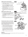
Replacing the Guide Wheel
a. Stop the tool and remove the battery pack.
b. Lay the edger on its back so that the guide
wheel is facing upwards.
c. Use the multi-function wrench to loosen
the nut in the COUNTERCLOCKWISE
direction and remove it.
d. Remove the plain washer and guide wheel
from the axle (Fig. 7). Check and replace
them if they are worn.
e. Mount the new wheel, and then mount the
plain washer and nut onto the axle in the
order shown in Fig. 7. And secure them in
place.
Replacing the Debris Flap
a. Stop the tool and remove the battery pack.
b. Use 10 mm wrench or adjustable wrench
(not included) to loosen the two nuts in
the COUNTERCLOCKWISE direction and
remove them.
c. Remove the plain washers and worn debris
ap (Fig. 8).
d. Replace with a new debris ap and secure
it with the two plain washers and nuts.
Transmission Gears Lubrication
The transmission gears in the gear case need
to be lubricated periodically with gear grease.
Check the gear case grease level about every
30 hours of operation by removing the sealing
screw on the side of the case.
a. Position the edger upright so that the
sealing screw is facing upwards (Fig. 9).
b. Use a 5 mm hex key (not included) to
loosen and remove the sealing screw.
c. Use a grease syringe (not included) to
inject some grease into the lubrication
opening; do not exceed 3/4 capacity. Do
not completely ll the transmission gear
case.
d. Tighten the sealing screw after injection.
Service
We recommend that all tool service be performed by a SKIL Factory Service Center or
Authorized SKIL Service Station.
Fig. 7 Nut
Plain washer
Guide wheel
Axle
Fig. 8
Plain washer
Nut
Fig. 9
Sealing
screw
Lubrication
opening

18
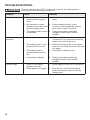
TROUBLESHOOTING
WARNING Turn the switch to the “OFF” position and remove the battery before
performing troubleshooting procedures.
Problem Cause Remedy
Tool fails to start. 1. The battery pack is not
attached to the power
head.
1. Attach the battery pack to the power
head.
2. No electrical contact
between the power head
and the battery pack.
2. Remove battery pack, check
contacts, and reinstall the battery
pack until it snaps into place.
3. The battery pack charge
is depleted. 3. Charge the battery pack with
chargers listed in the PH0040
manual.
Tool stops during
operation.
1. The tool is overloaded. 1. The tool will recover when the load
is removed. For continuous working,
reduce the load on the tool.
2. The battery pack or the
power head is too hot. 2. Allow the battery pack or the power
head to cool down, and then start the
tool again.
3. The battery pack is
disconnected from the
tool.
3. Re-install the battery pack.
4. Low battery capacity. 4. Charge the battery pack with
chargers listed in the PH0040
manual.
Uneven edge. 1. Grass or soil being
edged is too wet. 1. Avoid edging in wet soil or wet grass.
2. Blade guard is clogged. 2. Stop the tool, remove the battery
pack, and remove debris from the
blade guard.

19
LIMITED WARRANTY OF SKIL CONSUMER TOOLS
5 YEAR LIMITED WARRANTY
Chervon North America, Inc. ("Seller") warrants to the original purchaser only, that all SKIL
consumer TOOLS will be free from defects in material or workmanship for a period of ve
years from date of purchase, if original purchaser registers the product within 30 days from
purchase. BATTERIES AND CHARGERS are warranted for 2 years. Product registration
can be completed online at www.Registermyskil.com. Original purchasers should also retain
their receipt as proof of purchase. THE FIVE-YEAR WARRANTY PERIOD FOR TOOLS IS
CONDITIONED ON REGISTRATION OF THE PRODUCT WITHIN 30 DAYS OF PURCHASE.
If original purchasers do not register their product timely, the foregoing limited warranty will
apply for a duration of three years for tools. All batteries and chargers will remain under the
two-year limited warranty.
Notwithstanding the foregoing, if a SKIL consumer tool is used for industrial, professional
or commercial purposes, the foregoing warranty will apply for a duration of ninety days,
regardless of registration.
SELLER’S SOLE OBLIGATION AND YOUR EXCLUSIVE REMEDY under this Limited
Warranty and, to the extent permitted by law, any warranty or condition implied by law, shall
be the repair or replacement of parts, without charge, which are defective in material or
workmanship and which have not been misused, carelessly handled, or repaired by persons
other than Seller or Authorized Service Station. To make a claim under this Limited Warranty,
you must return the complete product, transportation prepaid, to any SKIL Factory Service
Center or Authorized Service Station. For Authorized SKIL Power Tool Service Stations,
please visit www.Registermyskil.com or call 1-877-SKIL-999 (1-877-754-5999).
THIS LIMITED WARRANTY DOES NOT APPLY TO ACCESSORY ITEMS SUCH AS
CIRCULAR SAW BLADES, DRILL BITS, ROUTER BITS, JIGSAW BLADES, SANDING
BELTS, GRINDING WHEELS AND OTHER RELATED ITEMS.
ANY IMPLIED WARRANTIES APPLICABLE TO A PRODUCT SHALL BE LIMITED IN
DURATION EQUAL TO THE DURATION OF THE EXPRESS WARRANTIES APPLICABLE
TO SUCH PRODUCT, AS SET FORTH IN THE FIRST PARAGRAPH ABOVE. SOME STATES
IN THE U.S., SOME CANADIAN PROVINCES DO NOT ALLOW LIMITATIONS ON HOW
LONG AN IMPLIED WARRANTY LASTS, SO THE ABOVE LIMITATION MAY NOT APPLY TO
YOU.
IN NO EVENT SHALL SELLER BE LIABLE FOR ANY INCIDENTAL OR CONSEQUENTIAL
DAMAGES (INCLUDING BUT NOT LIMITED TO LIABILITY FOR LOSS OF PROFITS)
ARISING FROM THE SALE OR USE OF THIS PRODUCT. SOME STATES IN THE U.S.
AND SOME CANADIAN PROVINCES DO NOT ALLOW THE EXCLUSION OR LIMITATION
OF INCIDENTAL OR CONSEQUENTIAL DAMAGES, SO THE ABOVE LIMITATION OR
EXCLUSION MAY NOT APPLY TO YOU.
THIS LIMITED WARRANTY GIVES YOU SPECIFIC LEGAL RIGHTS, AND YOU MAY ALSO
HAVE OTHER RIGHTS WHICH VARY FROM STATE TO STATE IN THE U.S., PROVINCE
TO PROVINCE IN CANADA AND FROM COUNTRY TO COUNTRY.
THIS LIMITED WARRANTY APPLIES ONLY TO PRODUCTS SOLD WITHIN THE UNITED
STATES OF AMERICA, CANADA AND THE COMMONWEALTH OF PUERTO RICO. FOR
WARRANTY COVERAGE WITHIN OTHER COUNTRIES, CONTACT YOUR LOCAL SKIL
DEALER OR IMPORTER.
© Chervon North America, 1203 E. Warrenville Rd, Naperville, IL 60563.

20
TABLE DES MATIÈRES
Consignes de sécurité importantes. . . . . . . . . . . . . . . . . . . . . . . . . . . . . 21-22
Symboles ..................................................23-26
Familiarisez-vous avec votre attachement de coupe-bordure ..........27
Spécications .................................................27
Assemblage ...................................................29
Instructions pour l’utilisation ..................................30-32
Maintenance ................................................ 33-35
Recherche de la cause des problèmes .............................36
Garantie limitée des outils grand public SKIL .......................37
La page charge ...
La page charge ...
La page charge ...
La page charge ...
La page charge ...
La page charge ...
La page charge ...
La page charge ...
La page charge ...
La page charge ...
La page charge ...
La page charge ...
La page charge ...
La page charge ...
La page charge ...
La page charge ...
La page charge ...
La page charge ...
La page charge ...
La page charge ...
La page charge ...
La page charge ...
La page charge ...
La page charge ...
La page charge ...
La page charge ...
La page charge ...
La page charge ...
La page charge ...
La page charge ...
La page charge ...
La page charge ...
La page charge ...
La page charge ...
La page charge ...
La page charge ...
-
 1
1
-
 2
2
-
 3
3
-
 4
4
-
 5
5
-
 6
6
-
 7
7
-
 8
8
-
 9
9
-
 10
10
-
 11
11
-
 12
12
-
 13
13
-
 14
14
-
 15
15
-
 16
16
-
 17
17
-
 18
18
-
 19
19
-
 20
20
-
 21
21
-
 22
22
-
 23
23
-
 24
24
-
 25
25
-
 26
26
-
 27
27
-
 28
28
-
 29
29
-
 30
30
-
 31
31
-
 32
32
-
 33
33
-
 34
34
-
 35
35
-
 36
36
-
 37
37
-
 38
38
-
 39
39
-
 40
40
-
 41
41
-
 42
42
-
 43
43
-
 44
44
-
 45
45
-
 46
46
-
 47
47
-
 48
48
-
 49
49
-
 50
50
-
 51
51
-
 52
52
-
 53
53
-
 54
54
-
 55
55
-
 56
56


Skil PED0900 PWR Core 40 9 in. Edger Attachment Le manuel du propriétaire
- Catégorie
- Outils électroportatifs
- Taper
- Le manuel du propriétaire
dans d''autres langues
Autres documents
-
EGO EA0800 Le manuel du propriétaire
-
-
-
-
-
Ryobi P2300A Le manuel du propriétaire
-
-
-