
INSTALLATIONINSTRUCTIONS
30" (76.0 CM) FREESTANDING ELECTRICRANGES
INSTRUCTIONSD'INSTALLATION DESCUISINIERES
ELECTRIQUESAUTOPORTANTESDE 30" (76,0 CM)
TableofContents/Table desmati@res
RANGE SAFETY ............................................................................. 2 SI_CURITI_ DE LA CUlSINIi::RE ................................................... 17
INSTALLATION REQUIREMENTS ................................................ 3
Tools and Parts ............................................................................ 3
Location Requirements ................................................................ 3
Electrical Requirements - U.S.A. Only ......................................... 5
INSTALLATION INSTRUCTIONS .................................................. 6
Unpack Range .............................................................................. 6
Install Anti-Tip Bracket ................................................................. 6
Electrical Connection - U.S.A. Only ............................................. 8
Verify Anti-Tip Bracket Is Installed and Engaged ...................... 12
Level Range ................................................................................ 13
Warming Drawer or Premium Storage Drawer .......................... 13
Storage Drawer .......................................................................... 14
Oven Door .................................................................................. 14
Complete Installation ................................................................. 15
Moving the Range ...................................................................... 15
EXIGENCES D'INSTALLATION ................................................... 18
Outils et pieces ........................................................................... 18
Exigences d'emplacement ......................................................... 18
Specifications electriques - €:tats-Unis seulement ................... 20
INSTRUCTIONS D'INSTALLATION ............................................. 21
Deballage de la cuisiniere .......................................................... 21
Installation de la bride antibasculement .................................... 21
Raccordement electrique - €:tats-Unis seulement .................... 23
Verifier que la bride antibasculement est
bien installee et engagee ............................................................ 28
Reglage de I'aplomb de la cuisiniere ......................................... 28
Tiroir-rechaud ou tiroir de remisage de qualite superieure .......29
Tiroir de remisage ....................................................................... 29
Porte du four ............................................................................... 30
Achever I'installation .................................................................. 30
Deplacement de la cuisiniere ..................................................... 31
iMPORTANT:
Save for local electrical inspector's use.
iMPORTANT :
A conserver pour consultation par I'inspecteur local des installations electriques.
W10720128A

RANGESAFETY
Your safety and the safety of others are very important.
We have provided many important safety messages in this manual and on your appliance. Always read and obey all safety
messages.
This is the safety alert symbol.
This symbol alerts you to potential hazards that can kill or hurt you and others.
All safety messages will follow the safety alert symbol and either the word "DANGER" or "WARNING."
These words mean:
You can be killed or seriously injured if you don't immediately
follow instructions.
You can be killed or seriously injured if you don't follow
instructions.
All safety messages will tell you what the potential hazard is, tell you how to reduce the chance of injury, and tell you what can
happen if the instructions are not followed.
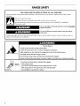
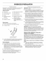
Anti-Tip
Bracket
Range Foot
Tip Over Hazard
A child or adult can tip the range and be killed.
Install anti-tip bracket to floor or wall per installation instructions.
Slide range back so rear range foot is engaged in the slot of the anti-tip bracket.
Re-engage anti-tip bracket if range is moved.
Do not operate range without anti-tip bracket installed and engaged.
Failure to follow these instructions can result in death or serious burns to children and adults.
To verify the anti-tip bracket is installed and engaged:
• Slide range forward.
• Look for the anti-tip bracket securely attached to floor or wall.
• Slide range back so rear range foot is under anti-tip bracket.
• See installation instructions for details.
2

INSTALLATIONREQUIREMENTS
Gather the required tools and parts before starting installation.
Read and follow the instructions provided with any tools listed
here.
Tools needed
• Tape measure
• Flat-blade screwdriver
• Phillips screwdriver
• Level
• Hand or electric drill
• Wrench or pliers
• Marker or pencil
• Masking tape
• 1¼.drive ratchet
• 1¼.nut driver
• 3/8"and S/le"nut driver
• 1/8"(3.2 mm) drill bit (for
wood floors)
• Tin snips or large wire
cutters (for cutting ground
strap if necessary)
Parts supplied
Check that all parts are included.
• 3 - 10-32 hex nuts (attached to terminal block)
• 3 - Terminal lugs
A.Anti-tip bracket
B.#12 x 1_" screws (2)
Anti-tip bracket must be securely mounted to floor or wall.
Thickness of flooring may require longer screws to anchor
bracket to floor.
Parts needed
If using a power supply cord kit:
• A UL listed power supply cord kit marked for use with ranges.
The cord should be rated at 250 volts minimum, 40 amps or
50 amps that is marked for use with nominal 13/8"(3.5 cm)
diameter connection opening and must end in ring terminals
or open-end spade terminals with upturned ends.
• A UL listed strain relief.
Check local codes. Check existing electrical supply. See the
appropriate "Electrical Requirements" section.
It is recommended that all electrical connections be made by a
licensed, qualified electrical installer.
IMPORTANT: Observe all governing codes and ordinances.
• It is the installeCs responsibility to comply with installation
clearances specified on the model/serial rating plate. The
model/serial rating plate is located on the frame behind a top
corner of the door or either side of the drawer.
To eliminate the risk of burns or fire by reaching over heated
surface units, cabinet storage space located above the
surface units should be avoided. If cabinet storage is to be
provided, the risk can be reduced by installing a range hood
that projects horizontally a minimum of 5" (12.7 cm) beyond
the bottom of the cabinets.
Cabinet opening dimensions that are shown must be used.
Given dimensions are minimum clearances.
The anti-tip bracket must be installed. To install the anti-tip
bracket shipped with the range, see "Install Anti-Tip Bracket"
section.
• Grounded electrical supply is required. See the appropriate
"Electrical Requirements" section.
IMPORTANT: To avoid damage to your cabinets, check with your
builder or cabinet supplier to make sure that the materials used
will not discolor, delaminate or sustain other damage. This oven
has been designed in accordance with the requirements of UL
and CSA International and complies with the maximum allowable
wood cabinet temperatures of 194° (90°C).
Mobile Home - Additional Installation Requirements
The installation of this range must conform to the Manufactured
Home Construction and Safety Standard, Title 24 CFR, Part 3280
(formerly the Federal Standard for Mobile Home Construction
and Safety, Title 24, HUD Part 280). When such standard is not
applicable, use the Standard for Manufactured Home
Installations, ANSI A225.1/NFPA 501A or local codes.
Mobile home installations require:
• When this range is installed in a mobile home, it must be
secured according to the instructions in this document.
• Four-wire power supply cord or cable must be used in a
mobile home installation. The appliance wiring will need to be
revised. See "Electrical Connection - U.S.A. Only" section.

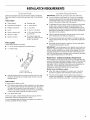
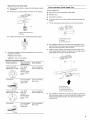
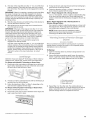
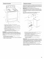
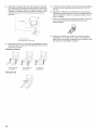
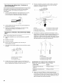
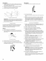
Product Dimensions
A
B
E
A. 27_" (70.5 cm) max. depth with handle
B. 46 z_''(119.1 cm) overall height (max.) with levering legs
screwed all the way in*
C. 36" (91.4 cm) cooktop height (max.) with leveling legs screwed
aft the way in*
D. 29 z_,,(75.9 cm) width
E. 25 5_,, (64.3 cm) depth - back of range to front of cooktop**
E Model/serial rating plate (located on the frame behind a top
corner of the door or either side of the drawer)
IMPORTANT: Range must be level after installation. Follow the
instructions in the "Level Range" section. Using the cooktop as a
reference for leveling the range is not recommended.
*Range can be raised approximately 1" (2.5 cm) by adjusting
the leveling legs.
**Front of door and drawer may extend further forward
depending on styling.
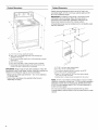
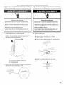
Cabinet Dimensions
Cabinet opening dimensions shown are for 25" (64.0 cm)
countertop depth, 24" (61.0 cm) base cabinet depth and 36"
(91.4 cm) countertop height.
IMPORTANT: If installing a range hood or microwave hood
combination above the range, follow the range hood or
microwave hood combination installation instructions for
dimensional clearances above the cooktop surface.
A freestanding range may be installed next to combustible walls
with zero clearance.
D
E
\
\
\
\
\
F
A. 15" (38.1 cm) max. upper cabinet depth
B. 30" (76.2 cm) min. opening width
C. For minimum clearance to top of cooktop, see NOTE*
D. 30 _" (76.5 cm) min. opening width
E. Outlet - 8" (20.3 cm) to 22" (55.9 cm) from either cabinet,
5½" (14.0 cm) max. from floor
E Cabinet door or hinges should not extend into the cutout
*NOTE: 24" (61.0 cm) minimum when bottom of wood or metal
cabinet is covered by not less than 1/4"(0.64 cm) flame retardant
millboard covered with not less than No. 28 MSG sheet steel,
0.015" (0.4 mm) stainless steel, 0.024" (0.6 mm) aluminum or
0.020" (0.5 mm) copper.
30" (76.2 cm) minimum clearance between the top of the
cooking platform and the bottom of an uncovered wood or metal
cabinet.

Ifcodespermitandaseparategroundwireisused,itis
recommendedthataqualifiedelectricalinstallerdeterminethat
thegroundpathandwiregaugeareinaccordancewithlocal
codes.
Donotuseanextensioncord.
Besurethattheelectricalconnectionandwiresizeareadequate
andinconformancewiththeNationalElectricalCode,ANSI/
NFPA70-latesteditionandalllocalcodesandordinances.
Acopyoftheabovecodestandardscanbeobtainedfrom:
NationalFireProtectionAssociation
1BatterymarchPark
Quincy,MA02169-7471
WARNING:Improperconnectionoftheequipment-grounding
conductorcanresultinariskofelectricshock.Checkwitha
qualifiedelectricianorservicetechnicianifyouareindoubtasto
whethertheapplianceisproperlygrounded.Donotmodifythe
powersupplycordplug.Ifitwillnotfittheoutlet,haveaproper
outletinstalledbyaqualifiedelectrician.
Electrical Connection
To properly install your range, you must determine the type of
electrical connection you will be using and follow the instructions
provided for it here.
• Range must be connected to the proper electrical voltage
and frequency as specified on the model/serial rating plate.
The model/serial rating plate is located on the frame behind a
top corner of the door or either side of the drawer. Refer to
the figures in "Product Dimensions" in the "Location
Requirements" section.
• This range is manufactured with the neutral terminal
connected to the cabinet. Use a 3-wire, UL listed, 40- or 50-
amp power supply cord (pigtail) (see the following Range
Rating chart). If local codes do not permit ground through the
neutral, use a 4-wire power supply cord rated at 250 volts,
40 or 50 amps and investigated for use with ranges.
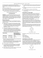
Range Rating* Specified Rating of
Power Supply Cord Kit
and Circuit Protection
120/240 Volts 120/208 Volts Amps
8.8 - 16.5 KW 7.8 - 12.5 KW 40 or 50**
16.6 - 22.5 KW 12.6 - 18.5 KW 50
*The NEC calculated load is less than the total connected load
listed on the model/serial rating plate.
**If connecting to a 50-amp circuit, use a50-amp rated cord with
kit. For 50-amp rated cord kits, use kits that specify use with a
nominal 13/8"(34.9 mm) diameter connection opening.
A circuit breaker is recommended.
The range can be connected directly to the circuit breaker
box (or fused disconnect) through flexible or nonmetallic
sheathed, copper or aluminum cable. See the "Electrical
Connection - U.S.A. Only" section.
Allow at least 6 ft (1.8 m) of slack in the line so that the range
can be moved if servicing is ever necessary.
• A UL listed conduit connector must be provided at each end
of the power supply cable (at the range and at the junction
box).
• Wire sizes and connections must conform with the rating of
the range.
• The wiring diagram is located on the Tech Sheet.
• The Tech Sheet is located on the back of the range inside a
clear plastic bag.
If connecting to a 4-wire system:
This range is manufactured with the ground connected to the
neutral by a link. The ground must be revised so the green
ground wire of the 4-wire power supply cord is connected to the
cabinet. See "Electrical Connection - U.S.A. Only" section.
Grounding through the neutral conductor is prohibited for new
branch-circuit installations (1996 NEC); mobile homes; and
recreational vehicles, or an area where local codes prohibit
grounding through the neutral conductor.
When a 4-wire receptacle of NEMA Type 14-50R is used, a
matching UL listed, 4-wire, 250-volt, 40- or 50-amp, range power
supply cord (pigtail) must be used. This cord contains 4 copper
conductors with ring terminals or open-end spade terminals with
upturned ends, terminating in a NEMA Type 14-50P plug on the
supply end.
The fourth (grounding) conductor must be identified by a green or
green/yellow cover and the neutral conductor by a white cover.
Cord should be Type SRD or SRDT with a UL listed strain relief
and be at least 4 ft (1.22 m) long.
4-wire receptacle (14-50R)
The minimum conductor sized for the copper 4-wire power
cord are:
40-amp circuit
2 No.-8 conductors
1 No.-10 white neutral
1 No.-10 green grounding
If connecting to a 3-wire system:
Local codes may permit the use of a UL listed, 3-wire, 250-volt,
40- or 50-amp range power supply cord (pigtail). This cord
contains 3 copper conductors with ring terminals or open-end
spade terminals with upturned ends, terminating in a NEMA Type
10-50P plug on the supply end. Connectors on the appliance end
must be provided at the point the power supply cord enters the
appliance. This uses a 3-wire receptacle of NEMA Type 10-50R.
3-wire receptacle (10-50R)

INSTALLATIONINSTRUCTIONS
' .... * Bsn,ge
1,
2.
3.
4,
6
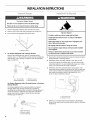
Excessive Weight Hazard
Use two or more people to move and install range.
Failure to do so can result in back or other injury.
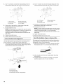
Remove shipping materials, tape and film from range.
Remove oven racks and parts package from inside oven.
Do not remove the shipping base at this time.
A.Shipping base
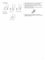
On Ranges Equipped with a Storage Drawer:
Remove the storage drawer. See the "Storage Drawer"
section. Use a 1¼,,drive ratchet to lower the rear leveling legs
one-half turn. Use a wrench or pliers to lower front leveling
legs one-half turn.
A
D
C
B
A. ¼" drive ratchet
B. Rear levering leg
C. Wrench or pliers
D. Front leveling leg
On Ranges Equipped with a Warming Drawer or Premium
Storage Drawer:
On ranges equipped with a warming drawer or premium
storage drawer, the rear legs cannot be accessed by
removing the warming drawer or premium storage drawer. It
will be necessary to adjust the rear legs from outside the
range. Use wrench or pliers to lower the front and rear
leveling legs one-half turn.
A
rx
a,
7777777777/
C
\
B
A. Rear levering leg
B. Wrench or pliers
C. Front leveling leg
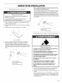
Tip Over Hazard
A child or adult can tip the range and be killed.
Install anti-tip bracket to floor or wall per installation
instructions.
Slide range back so rear range foot is engaged in the
slot of the anti-tip bracket.
Re-engage anti-tip bracket if range is moved.
Do not operate range without anti-tip bracket installed
and engaged.
Failure to follow these instructions can result in death
or serious burns to children and adults.
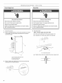
1. Remove the anti-tip bracket from where it is taped inside the
storage drawer or warming drawer.
2. Determine which mounting method to use: floor or wall.
If you have a stone or masonry floor, you can use the wall
mounting method. If you are installing the range in a mobile
home, you must secure the range to the floor.
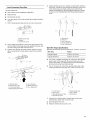
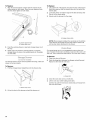
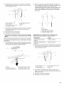
3. Determine and mark centerline of the cutout space. The
mounting can be installed on either the left side or right side
of the cutout. Position mounting bracket against the wall in
the cutout so that the V-notch of the bracket is 12%6"
(31.9 cm) from centerline as shown.
/
4,
Ceot rlioe! {
1
/I/I/ _ J--
/
A. 12_" (31.9 cm)
B. Bracket V-notch
Drill two 1/8"(3 mm) holes that correspond to the bracket
holes of the determined mounting method. See the following
illustrations.

Floor Mounting
Roarposition
Wall Mounting
Front position Diagonal (2 options)
5. Using the Phillips screwdriver, mount anti-tip bracket to the
wall or floor with the two #12 x 15/8"screws provided.
6. Move range close enough to opening to allow for final
electrical connections. Remove shipping base, cardboard or
hardboard from under range.
7. Move range into its final location, making sure rear leveling
leg slides into anti-tip bracket.
8.
Move range forward onto shipping base, cardboard or
hardboard to continue installing the range using the following
installation instructions.

Power Supply Cord Direct Wire
EJectricai Shock Hazard
Disconnect power before servicing.
Use a new 40 amp power supply cord.
Plug into a grounded outlet.
Failure to foiJow these instructions can resuJt in death,
fire, or eJectricai shock.
EJectricai Shock Hazard
Disconnect power before servicing.
Use 8 gauge copper or 6 gauge aluminum wire.
Electrically ground range.
Failure to foiJow these instructions can resuJt in death,
fire, or eJectricai shock.
1=
2.
3.
Disconnect power.
Remove the terminal block cover screws located on the back
of the range. Pull cover down and toward you to remove
cover from range.
C
A.Two mounting tabs eachside
B.Terminalblock cover
C.Hex-head screws
Remove plastic tag holding three 10-32 hex nuts from the
middle post of the terminal block.
4= Add strain relief.
Style 1: Power supply cord strain relief
• Remove the knockout for the power supply cord.
• Assemble a UL listed strain relief in the opening.
A. UL fistedstrainrelief
Tighten strain relief screw against the power supply cord.
8

Style 2: Direct wire strain relief
• Remove the knockout as needed for the flexible conduit
connection.
• Assemble a UL listed conduit connector in the opening.
4-wire connection: Power Supply Cord
Use this method for:
• New branch-circuit installations (1996 NEC)
• Mobile homes
• Recreational vehicles
• In an area where local codes prohibit grounding through the
neutral
1. Part of metal ground strap must be cut out and removed.
A. Removable retaining nut
B. Conduit
• Tighten strain relief screw against the flexible conduit.
5. Complete installation following instructions for your type of
electrical connection:
4-wire (recommended)
3-wire (if 4-wire is not available)
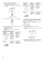
Electrical Connection Options
If your home has: And you will be Go to Section:
connecting to:
4-wire receptacle A UL listed,
(NEMA type 14-50R) 250-volt
minimum,
40-amp, range
power supply
cord
4-wire connection:
Power supply cord
4-wire direct
3/8_1
(1.ocm2....
(12.7 cm)
A circuit breaker
box or fused
disconnect
4-wire connection:
Direct wire
3-wire receptacle
(NEMA type 10-50R)
A UL listed,
250-volt
minimum,
40-amp, range
power supply
cord
3-wire connection:
Power supply cord
..J
A. Metal ground strap
B. Discard
C. Ground-link screw
"A
B
C
2. Use a Phillips screwdriver to remove the ground-link screw
from the back of the range. Save the ground-link screw and
the end of the ground link under the screw.
3. Feed the power supply cord through the strain relief on the
cord/conduit plate on bottom of range. Allow enough slack to
easily attach the wiring to the terminal block.
4=
A ....................__
©
D
A. Terminal block
B. Ground-link screw
C. UL fisted strain relief
D. Power supply cord wires
Use a Phillips screwdriver to connect the green ground wire
from the power supply cord to the range with the ground-link
screw and ground-link section. The ground wire must be
attached first.
3-wire direct A circuit breaker 3-wire connection:
box or fused Direct wire
3/8" disconnect
(7.6 cm)

5. Use 3/8"nut driver to connect the neutral (white) wire to the
center terminal block post with one of the 10-32 hex nuts.
2. Use 3/8"nut driver to connect the neutral (white) wire to the
center terminal block 30st with one of the 10-32 hex nuts.
B
C
F
D
A. 10-32 hex nut
B. Ground-link screw
C. Line 2 (red)
D. Green ground wire
E.Neutral (center) wire
F. Line 1 (black)
6. Connect line 2 (red) and line 1 (black) wires to the outer
terminal block posts with 10-32 hex nuts.
7. Securely tighten hex nuts.
NOTE: For power supply cord replacement, use only a power
cord rated at 250 volts minimum, 40 amps or 50 amps that is
marked for use with nominal 13/8"(3.5 cm) diameter
connection opening, with ring terminals and marked for use
with ranges.
8. Tighten strain relief screws.
9. Replace terminal block access cover.
3-wire connection: Power Supply Cord
Use this method only if local codes permit connecting chassis
ground conductor to neutral wire of power supply cord.
1. Feed the power supply cord through the strain relief on the
cord/conduit plate on bottom of range. Allow enough slack to
easily attach the wiring to the terminal block.
A
i
B
C
A. 10-32 hex nut
B. Line 2 (red)
C. Ground-link screw
E
D. Neutral (white) wire
E.Line 1 (black)
3. Connect line 2 (red) and line 1 (black) wires to the outer
terminal block posts with 10-32 hex nuts.
4. Securely tighten hex nuts.
NOTE: For power supply cord replacement, use only a power
cord rated at 250 volts minimum, 40 amps or 50 amps that is
marked for use with nominal 13/8'' (3.5 cm) diameter
connection opening, with ring terminals and marked for use
with ranges.
5. Tighten strain relief screws.
6. Replace terminal block access cover.
Direct Wire Installation: Copper or Aluminum Wire
This range may be connected directly to the fuse disconnect or
circuit breaker box. Depending on your electrical supply, make
the required 3-wire or 4-wire connection.
1. Strip outer covering back 3" (7.6 cm) to expose wires. Strip
the insulation back 3/8"(1.0 cm) from the end of each wire.
3/8t_
(7.6 cm)
2. Allow enough slack in the wire to easily attach the wiring
terminal block.
3. Complete electrical connection according to your type of
electrical supply (4-wire or 3-wire connection).
A. Terminal block
B. Ground-link screw
C. UL listed strain relief
D. Power supply cord wires - large opening
10

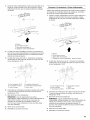
4-wire Connection: Direct Wire
Use this method for:
• New branch-circuit installations (1996 NEC)
• Mobile homes
• Recreational vehicles
• In an area where local codes prohibit grounding through the
neutral
1. Part of metal ground strap must be cut out and removed.
A
B
C
A. Metal ground strap
B. Discard
C. Ground-link screw
2. Use a Phillips screwdriver to remove the ground-link screw
from the back of the range. Save the ground-link screw and
the end of the ground link under the screw.
3. Pull the wires through the strain relief on bottom of range.
Allow enough slack to easily attach wiring to the terminal
block.
A .....................
............ i
l
©
4=
Attach terminal lugs to line 1(black), neutral (white), and line 2
(red) wires. Loosen (do not remove) the setscrew on the front
of the terminal lug and insert exposed wire end through
bottom of terminal lugs. Securely tighten setscrew to torque
as shown in the following Bare Wire Torque Specifications
chart.
A
C
m H H
H m |
H m m
A.Terminallug
B.Setscrew
C.Line 2 (red)wire
D.Neutral (white) wire
E.Line 1(black)wire
Bare Wire Torque Specifications
Attaching terminal lugs to the terminal block - 20 Ibs-in. (2.3 N-m)
Wire Awg Torque
8 gauge copper 25 Ibs-in. (2.8 N-m)
6 gauge aluminum 35 Ibs-in. (4.0 N-m)
5. Use a hex or Phillips screwdriver to connect the bare (green)
ground wire to the range with the ground-link screw and
ground-link section. The ground wire must be attached first
and must not contact any other terminal.
6. Use 3/8"nut driver to connect the neutral (white) wire to the
center terminal block 30st with one of the 10-32 hex nuts.
A. Terminal block
B. Ground-link screw
C. Cord/conduit plate
D. Bare (green) ground wire
E.Line 2 (red) wire
F. Neutral (white) wire
G. Line 1 (black) wire
A
G
C
A. 10-32 hex nut
B. Line 2 (red)
C. Bare (green) ground wire
D. Ground-link screw
D
E
E.Neutral (white) wire
F. Line 1 (black)
G. Terminal lug
7. Connect line 2 (red) and line 1 (black) wires to the outer
terminal block posts with 10-32 hex nuts.
8. Securely tighten hex nuts.
9. Replace terminal block access cover.
11

3-wire connection: Direct Wire
Use this method only if local codes permit connecting ground
conductor to neutral supply wire.
1. Pull the wires through the conduit on cord/conduit plate on
bottom of range. Allow enough slack to easily attach the
wiring to the terminal block.
B
©
©
2.
A. Terminal block
B. Ground-link screw
C. Cord/conduit plate
D. Line 2 (red) wire
E. Bare (green) ground wire
F. Line 1 (black) wire
Attach terminal lugs to line 2 (red), bare (green) ground, and
line 1 (black) wires. Loosen (do not remove) the setscrew on
the front of the terminal lug and insert exposed wire end
through bottom of terminal lugs. Securely tighten setscrew to
torque as shown in the following Bare Wire Torque
Specifications chart.
A
i
i |
m
m
|
C D
A. Terminal lug
B. Setscrew
C. Line 2 (red) wire
D. Bare (green) ground wire
E.Line 1 (black) wire
Bare Wire Torque Specifications
Attaching terminal lugs to the terminal block - 20 Ibs-in. (2.3 N-m)
Wire Awg Torque
8 gauge copper 25 Ibs-in. (2.8 N-m)
6 gauge aluminum 35 Ibs-in. (4.0 N-m)
3.
Use 3/8"nut driver to connect the bare (green) ground wire to
the center terminal block post with one of the 10-32 hex nuts.
iL
B
F
E
A. 10-32 hex nut
B. Line 2 (red)
C. Ground-link screw
D
C
D. Bare (green) ground wire
E.Line 1 (black)
F. Terminal lug
4. Connect line 2 (red) and line 1 (black) wires to the outer
terminal block posts with 10-32 hex nuts.
5. Securely tighten hex nuts.
6. Replace terminal block access cover.
On Ranges Equipped with a Storage Drawer:
1. Remove the storage drawer. See "Storage Drawer" section.
2. Use a flashlight to look underneath the bottom of the range.
3. Visually check that the rear range foot is inserted into the slot
of the anti-tip bracket.
On Ranges Equipped with a Warming Drawer or Premium
Storage Drawer:
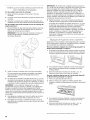
1. Place the outside of your foot against the bottom front of the
warming drawer or premium storage drawer, and grasp the
lower right or left side of the control panel as shown.
NOTE: If your countertop is mounted with a backsplash, it
may be necessary to grasp the range higher than is shown in
the illustration.
2.
_9
Slowly attempt to tilt the range forward.
If you encounter immediate resistance, the range foot is
engaged in the anti-tip bracket.
12

3. If the rear of the range lifts more than 1/2"(1.3 cm) off the floor
without resistance, stop tilting the range and lower it gently
back to the floor. The range foot is not engaged in the anti-tip
bracket.
IMPORTANT: If there is a snapping or popping sound when lifting
the range, the range may not be fully engaged in the bracket.
Check to see if there are obstructions keeping the range from
sliding to the wall or keeping the range foot from sliding into the
bracket. Verify that the bracket is held securely in place by the
mounting screws.
4. Slide the range forward, and verify that the anti-tip bracket is
securely attached to the floor or wall.
5. Slide range back so the rear range foot is inserted into the
slot of the anti-tip bracket.
IMPORTANT: If the back of the range is more than 2" (5.1 cm)
from the mounting wall, the rear range foot may not engage the
bracket. Slide the range forward and determine if there is an
obstruction between the range and the mounting wall. If you
need assistance or service, refer to the "Assistance or Service"
section of the Use and Care Guide, or the cover or "Warranty"
section of the User Instructions, for contact information.
6. Repeat steps 1 and 2 to ensure that the range foot is
engaged in the anti-tip bracket.
If the rear of the range lifts more than 1/2"(1.3 cm) off the floor
without resistance, the anti-tip bracket may not be installed
correctly. Do not operate the range without anti-tip bracket
installed and engaged. Please reference the "Assistance or
Service" section of the Use and Care Guide, or the cover or
"Warranty" section of the User Instructions, to contact
service.
L sge
Determine if you have AquaLift ®tTechnology or Steam Clean by
referring to the "Range Care" section of the User Instructions.
For Ranges with AquaLift ®Technology or Steam Clean:
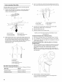
1. Place level on the oven bottom as indicated in one of the two
figures below depending on the size of the level. Check with
the level: side to side and front to back.
'\ /
3. If range is not level, pull range forward until rear leveling leg is
removed from the anti-tip bracket.
4. Follow the directions in Style 1 or Style 2, depending on the
style of drawer supplied with the range.
Style 1: Ranges Equipped with a Storage Drawer:
Use aW' drive ratchet, wrench or pliers to adjust leveling legs
up or down until the range is level. Push range back into
position. Check that rear leveling leg is engaged in the anti-tip
bracket.
Style 2: Ranges Equipped with a Warming Drawer or
Premium Storage Drawer:
Use a wrench or pliers to adjust leveling legs up or down until
the range is level. Push range back into position. Check that
rear leveling leg is engaged in the anti-tip bracket.
NOTE: Range must be level for satisfactory baking
performance and best cleaning results using AquaLift ®
Technology and Steam Clean functions.
Remove all items from inside the warming drawer or premium
storage drawer, and allow the range to cool completely before
attempting to remove the drawer.
To Remove:
1. Open the warming drawer or premium storage drawer to its
fully open position.
2. Using a flat-blade screwdriver, gently loosen the warming
drawer or premium storage drawer from the glide alignment
notch and lift up the drawer alignment tab from the glide.
2. If range is not level, pull range forward until rear leveling leg is
removed from the anti-tip bracket.
3. Follow the directions in Style 1 or Style 2, depending on the
style of drawer supplied with the range.
For Ranges without AquaLift _Technology or Steam Clean:
1. Place a standard flat rack in oven.
2. Place level on the rack and check levelness of the range, first
side to side; then front to back.
3.
A. Flat-blade screwdriver
B. Drawer afignment tab
C. Drawer glide notch
Repeat Step 2 on the other side. The warming drawer or
premium storage drawer is no longer attached to the drawer
glides. Using both hands, pick up the warming drawer or
premium storage drawer to complete the removal.
t® AQUALIFT is a registered trademark of Whirlpool, U.S.A.
13

To Replace:
1. Align the forward drawer notches with the notches in the
drawer glides on both sides. Place the rear alignment tabs
into the drawer glides on both sides.
A. Drawer alignment tab
B. Drawer glide notch
2. Push the warming drawer or premium storage drawer in all
the way.
3. Gently open and close the warming drawer or premium
storage drawer to ensure it is seated properly on the glides
on both sides.
(on so_'__emodes}
The storage drawer can be removed. Before removing, make sure
drawer is cool and empty.
To Remove:
1. Pull the storage drawer straight back to the drawer stop.
To Replace:
1. Lift up the front of the drawer and place the rear of the drawer
inside the range so that the drawer stop notch is behind the
drawer glide.
2. Lower the drawer so that the edge of the slide rail drops into
the slot in the drawer glide.
3. Slowly push the drawer into the range.
A
\
A. Engage drawer glide.
NOTE: When properly installed, the rear slides on the bottom
of the drawer will engage the base rails and the drawer will
not tip when items are placed in the drawer.
For normal range use, it is not suggested to remove the oven
door. However, if removal is necessary, make sure the oven is off
and cool. Then, follow these instructions. The oven door is heavy.
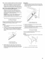
To Remove:
1. Open oven door all the way.
2. Pinch the hinge latch between two fingers and pull forward.
Repeat on other side of oven door.
2=
A
A.Drawer stop notch
Lift up the front of the drawer and pull the drawer out.
3=
4.
A. Hinge latch
Close the oven door as far as it will shut.
Lift the oven door while holding both sides.
Continue to push the oven door closed and pull it away from
the oven door frame.
14

To Replace:
1. Insert both hanger arms into the door.
_,_ _ _ _ _s¸_/U_s ¸
2. Open the oven door.
You should hear a "click" as the door is set into place.
3. Move the hinge levers back to the locked position. Check
that the door is free to open and close. If it is not, repeat the
removal and installation procedures.
C;omp/eS} n@ s cs
1. Check that all parts are now installed. If there is an extra part,
go back through the steps to see which step was skipped.
2. Check that you have all of your tools.
3. Dispose of/recycle all packaging materials.
4. Check that the range is level. See the "Level Range" section.
5. Use a mild solution of liquid household cleaner and warm
water to remove waxy residue caused by shipping material.
Dry thoroughly with a soft cloth. For more information, read
the "Range Care" section of the Use and Care Guide or User
Instructions.
6. Read the "Range Use" section in the range Use and Care
Guide or User Instructions.
7. Plug power cord into appropriate outlet. Turn power on.
8. Turn on surface burners and oven. See the Use and Care
Guide or User Instructions for specific instruction on range
operation.
If range does not operate, check the following:
• Household fuse is intact and tight; or circuit breaker has not
tripped.
• Range is plugged into a grounded outlet.
• Electrical supply is connected.
IMPORTANT: If the range control displays an "F9" or "F9, E0"
error code, the electrical outlet in the home may be miswired.
Contact a qualified electrician to verify the electrical supply.
• See the "Troubleshooting" section in the Use and Care Guide
or User Instructions.
When the range has been on for 5 minutes, check for heat. If
range is cold, turn off the range and contact a qualified
technician.
Tip Over Hazard
A child or adult can tip the range and be killed.
Install anti-tip bracket to floor or wall per installation
instructions.
Slide range back so rear range foot is engaged in the
slot of the anti-tip bracket.
Re-engage anti-tip bracket if range is moved.
Do not operate range without anti-tip bracket installed
and engaged.
Failure to follow these instructions can result in death
or serious burns to children and adults.
When moving range, slide range onto cardboard or hardboard to
avoid damaging the floor covering.
If removing the range is necessary for cleaning or maintenance:
For power supply cord-connected ranges:
1. Slide range forward.
2. Unplug the power supply cord.
3. Complete cleaning or maintenance.
4. Plug in power supply cord.
5. Check that the anti-tip bracket is installed and engaged. See
the "Verify Anti-Tip Bracket Is Installed and Engaged"
section.
6. Check that range is level.
For direct-wired ranges:
Electrical Shock Hazard
Disconnect power before servicing.
Replace all parts and panels before operating.
Failure to do so can result in death or electrical shock.
1. Disconnect power.
2. Slide range forward.
3. Complete cleaning or maintenance.
4. Check that the anti-tip bracket is installed and engaged. See
the "Verify Anti-Tip Bracket Is Installed and Engaged" section.
5. Check that range is level.
6. Reconnect power.
15

16

SECURITEDELACUISINIERE
Votre securite et celle des autres est tres importante.
Nous donnons de nombreux messages de s_curit_ importants dans ce manuel et sur votre appareil m_nager. Assurez-vous de
toujours lire tousles messages de s_curit_ et de vous y conformer.
Voici le symbole d'alerte de s_curit&
Ce symbole d'alerte de s_curit_ vous signale les dangers potentiels de d_c_s et de blessures graves & vous
et & d'autres.
Tous les messages de s_curit_ suivront le symbole d'alerte de s_curit_ et le mot "DANGER" ou
"AVERTISSEMENT". Ces mots signifient •
Risque possible de d_cbs ou de blessure grave si vous ne
suivez pas imm_diatement les instructions.
Risque possible de d_cbs ou de blessure grave si vous
ne suivez pas les instructions.
Tous les messages de s_curit_ vous diront quel est le danger potentiel et vous disent comment r_duire le risque de blessure et
ce qui peut se produire en cas de non-respect des instructions.
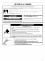
Risque de basculement
Un enfant ou une personne adulte peut faire basculer la cuisiniere, ce qui peut causer un
d_ces.
Fixer la bride antibasculement au plancher ou au mur, conform_ment aux instructions
d'installation.
Faire glisser de nouveau la cuisiniere de fa£on a ce que le pied arriere de la cuisiniere se
trouve dans la fente de la bride antibasculement.
R_engager la bride antibasculement si la cuisiniere a _t_ d_plac_e.
Ne pas faire fonctionner la cuisiniere si la bride antibasculement n'est pas install_e et engag_e.
Le non-respect de ces instructions peut causer un d_cbs ou des brl)lures graves aux enfants et
aux adultes.
Bride
antibasculement
Pied de
la cuisiniere
Pour v_rifier que la bride antibasculement est bien install_e et engag_e :
• Faire glisser la cuisiniere vers ravant.
• V_rifier que la bride antibasculement est bien fix_e au plancher ou au mur.
• Faire de nouveau glisser la cuisiniere vers rarriere de sorte que le pied de la cuisiniere
se trouve sous la bride antibasculement.
• Voir les instructions d'installation pour plus de d_tails.
17

EXIGENCESD'INSTALLATION
Rassembler les outils et pieces necessaires avant d'entreprendre
I'installation. Lire et observer les instructions fournies avec
chacun des outils de la liste ci-dessous.
Outils n_cessaires
• Metre-ruban
• Tournevis a lame plate
• Tournevis Phillips
• Niveau
• Perceuse manuelle ou
electrique
• Cle ou pince
• Marqueur ou crayon
• Ruban adhesif de masquage
• Cle & cliquet de 1¼,,
• Tourne-ecrou de W'
• Tourne-ecrou de 3/8"et 8/le"
• Foret de 1/8"(3,2 mm) (pour
planchers en bois)
• Cisaille de ferblantier ou
grosses cisailles (pour
couper la barrette de terre si
besoin)
Pi6ces fournies
Verifier que toutes les pieces sont presentes.
• 3 ecrous hexagonaux de 10-32 (joints au bornier)
• 3 cosses a bornes
B\
A. Bride antibasculement
B. Vis n° 12 x 1_" (2)
La bride antibasculement doit _tre bien fixee au plancher ou
au mur. La profondeur du plancher peut necessiter des vis
plus Iongues pour I'ancrage de la bride dans le sol.
Pi6ces n6cessaires
En cas d'utilisation d'un cordon d'alimentation electrique :
• Cordon d'alimentation (homologation UL) con9u pour
I'utilisation avec une cuisiniere. Pour service 250 volts
minimum, 40 A ou 50 A, compatible avec une ouverture de
diametre nominal 13/8'' (3,5 cm) pour le raccordement, et avec
cosses rondes ou en fourche & pointes relevees & I'extremite
de chaque conducteur.
• Un serre-c&ble (homologation UL).
Consulter les codes Iocaux. Verifier I'alimentation electrique
existante. Voir la section "Specifications electriques".
II est recommande de faire realiser tous les raccordements
electriques par un electricien qualifie agree.
Exi s®nc®s d emptcsc®m@:S
IMPORTANT : Observer les dispositions de tous les codes et
reglements en vigueur.
• C'est a I'installateur qu'incombe la responsabilite de
respecter les distances de separation specifiees sur la plaque
signaletique. La plaque signaletique est situee sur le ch&ssis
derriere un coin superieur de la porte ou d'un c6te du tiroir.
• Afin de supprimer le risque de brQlures ou d'incendie lie au
fait de se pencher au-dessus des plaques de cuisson
chaudes, les placards de rangement au-dessus des plaques
doivent _tre evites. Si des placards de rangement sont
envisages, le risque peut _tre reduit par I'instailation d'une
hotte de cuisiniere depassant le bas des placards d'au moins
5" (12,7 cm) horizontalement.
• Respecter les dimensions indiquees pour les ouvertures
decouper dans les placards. Ces dimensions constituent les
valeurs minimales des degagements.
• La bride antibasculement doit _tre installee. Pour I'instailation
de la bride antibasculement fournie avec la cuisiniere, voir la
section "Installation de la bride antibasculement'.
• Une source d'electricite avec liaison & la terre est necessaire.
Voir la section "Specifications electriques".
IMPORTANT : Afin d'eviter d'endommager les placards,
consulter I'installateur ou le fabricant des placards pour
determiner si les materiaux utilises peuvent subir un changement
de couleur, une destratification ou d'autres dommages. Ce four a
ete con£_uconformement aux exigences des normes UL et CSA
International et respecte les temperatures maximales permises
de 194° (90°C) pour les placards en bois.
R_sidence mobile - Sp6cifications additionnelles
respecter Iors de I'installation
L'installation de cette cuisiniere doit _tre conforme aux
dispositions de la norme Manufactured Home Construction and
Safety Standard, Title 24 CFR, Part 3280 (anciennement Federal
Standard for Mobile Home Construction and Safety, Title 24,
HUD Part 280). Lorsque cette norme n'est pas applicable, utiliser
la norme Standard for Manufactured Home Installations, ANSI
A225.1/NFPA 501A ou respecter les dispositions des codes
Iocaux.
Autres crit_res a respecter pour une installation en r_sidence
mobile :
• Lorsque cette cuisiniere est installee dans une residence
mobile, elle doit _tre fixee selon les instructions contenues
dans le present document.
• Pour une installation en residence mobile, un c&ble ou cordon
d'alimentation &quatre conducteurs doit _tre utilis& Le
c&blage de I'appareil devra _tre revise. Voir la section
"Raccordement electrique - €:tats-Unis seulement".
18

Dimensions du produit
A
B
E
A. Profondeur avec poign#e : 27 _" (70,5 cm) max.
C. Hauteur (max.) avec les pieds de nivellement completement
relev#s : 46z_ ''(119,1 cm)*
C. Hauteur de la garniture de la table de cuisson (max.) avec les
pieds de niveflement completement relev#s : 36" (91,4 cm)*
D. Largeur : 29z_ ''(75,9 cm)
E. Profondeur : 25 _" (64,3 cm) depuis I'arriere de la cuisiniere
jusqu'a I'avant de la table de cuisson**
F. Plaque signal#tique (situ#e sur le ch&ssis derriere un coin
sup#rieur de la porte ou d'un cSt# du tiroir)
IMPORTANT : La cuisiniere doit _tre d'aplomb apr_s
I'installation. Suivre les instructions de la section "Reglage de
I'aplomb de la cuisiniere". II n'est pas recommande d'utiliser la
table de cuisson comme ref6rence pour etablir I'aplomb de la
cuisiniere.
*La cuisiniere peut _tre surelev6e d'environ 1" (2,5 cm) en
ajustant les pieds de nivellement.
**L'avant de la porte et du tiroir peuvent s'avancer davantage en
fonction du style du produit.
Dimensions du placard
Les dimensions de I'espace d'installation entre les placards sont
valides pour I'installation entre des placards de 24" (61,0 cm) de
profondeur avec plan de travail de 25" (64,0 cm) de profondeur et
hauteur du plan de travail de 36" (91,4 cm).
IMPORTANT : En cas d'installation d'une hotte ou d'un
ensemble hotte/micro-ondes au-dessus de la cuisiniere, suivre
les instructions fournies avec la hotte concernant les dimensions
de degagement & respecter au-dessus de la surface de la table
de cuisson.
Une cuisiniere autoportante peut _tre installee sans aucun
degagement & proximite de parois combustibles.
D
E
\
\
\
\
F
A. Profondeur maximale des placards sup#rieurs de 15" (38,1 cm)
B. Largeur de I'ouverture 30" (76,2 cm) min.
C. Pour le d#gagement minimum vers la pattie sup#rieure de la
table de cuisson, voir la REMARQUE*.
D. Largeur minimale de I'ouverture : 30 _" (76,5 cm)
E. Prise - 8" (20,3 cm) a 22" (55,9 cm) de chaque cabinet, 5½"
(14,0 cm) max. du plancher
F. La porte ou charniere du placard ne dolt pas d_passer
I'int#rieur de I'ouverture.
*REMARQUE : Distance de separation minimale de 24" (61 cm)
Iorsque le fond d'un placard de bois ou de metal est proteg6 par
une planche ignifugee d'au moins 1/4"(0,64 cm) recouverte d'une
feuille metallique d'epaisseur egale ou superieure & : acier
calibre 28 MSG, acier inoxydable 0,015" (0,4 ram), aluminium
0,024" (0,6 mm), ou cuivre 0,020" (0,5 mm).
Distance de separation minimale de 30" (76,2 cm) entre le
dessus de la table de cuisson et lefond d'un placard de bois ou
de metal non proteg&
19

Si I'on utilise un conducteur distinct de liaison & la terre Iorsque
les codes le permettent, il est recommande qu'un electricien
qualifie verifie que la liaison & la terre et le calibre des
conducteurs sont conformes aux codes Iocaux.
Ne pas utiliser de c&ble de rallonge.
S'assurer que le raccordement electrique est adequat et conforme
au code national de I'electricit6, ANSI/NFPA 70 - derni#re edition,
et & tousles codes et reglements Iocaux en vigueur.
Pour obtenir un exemplaire des normes des codes ci-dessus,
contacter :
National Fire Protection Association
1 Batterymarch Park
Quincy, MA 02169-7471
AVERTISSEMENT • Un raccordement inapproprie du conducteur
de liaison & la terre peut causer un risque de choc electrique.
Verifier avec un electricien ou un technicien de depannage
qualifie en cas de doute quanta la qualite de la liaison &la terre
de I'appareil. Ne pas modifier la prise du cordon d'alimentation.
Si elle ne correspond pas & la prise de sortie, faire installer une
prise appropriee par un electricien qualifi&
Raccordement _lectrique
Pour installer la cuisiniere de fagon appropriee, il faut etablir le
type de raccords electriques que I'on utilisera et suivre les
instructions aux presentes.
• La cuisiniere doit _tre alimentee par une source d'electricite
et une tension appropriees, comme specifie sur la plaque
signaletique. La plaque signaletique est situee sur le chassis
derriere un coin superieur de la porte ou un c6te du tiroir.
Consulter les valeurs dans la rubrique "Dimensions du
produit" de la section "Exigences d'emplacement".
• La borne du neutre de cette cuisiniere est raccordee & la
caisse. Utiliser un cordon d'alimentation electrique (spirale de
raccord) a 3 conducteurs homologue UL, pour 40 ou 50 A
(voir le tableau de la puissance nominale de la cuisiniere). Si
les codes Iocaux ne permettent pas de relier I'appareil a la
terre par le conducteur neutre, utiliser un cable d'alimentation
a 4 conducteurs de tension nominale de 250 volts, 40 a
50 amperes, d'un calibre adequat pour le branchement de
cuisinieres.
• Un raccord de conduit homologue UL doit _tre fourni &
chaque extremite du cable d'alimentation electrique (a la
cuisiniere eta la boite de connexion).
• Le calibre des cables et des raccordements doit _tre
conforme a la puissance nominale de la cuisiniere.
• Le schema de cablage se trouve sur la fiche technique.
• Le schema de cablage est situe a I'arriere de la cuisiniere,
dans un sachet plastique transparent.
En cas de raccordement & un circuit _ 4 conducteurs :
Cette cuisiniere est fabriqu_e avec la terre connectee au neutre
par une liaison. Le circuit de terre doit _tre modifie pour que le
conducteur de terre vert du cordon d'alimentation electrique a
4 conducteurs soit raccorde a la caisse. Voir la section
"Raccordement electrique - €:tats-Unis seulement".
II est interdit de relier I'appareil a la terre par I'intermediaire du
conducteur neutre dans les cas suivants :nouvelle installation sur
circuit de derivation (code NEC 1996), residence mobile, vehicule
recreatif et juridictions oQ le code local interdit la liaison a la terre
par I'intermediaire du conducteur neutre.
En cas d'utilisation d'une prise murale a 4 conducteurs de type
NEMA 14-50R, un cordon d'alimentation electrique homologue
UL a4 conducteurs de 250 Vet 40 ou 50 A doit _tre utilise pour la
cuisiniere. Ce cordon contient 4 conducteurs en cuivre equipes
de bornes circulaires ou en fourche a extremites relevees et se
termine par une prise male de type NEMA Type 14-50P a
I'extremite d'alimentation.
Le quatrieme conducteur (mise & la terre) doit _tre identifie par
une gaine verte, ou vert et jaune, et leconducteur neutre doit _tre
identifie par une gaine blanche. Le cordon doit _tre de type SRD
ou SRDT, _tre equipe d'un serre-cable homologu_ UL et mesurer
au moins 4 pi (1,22 m) de long.
Prise murale a 4 conducteurs (14-50R)
Puissance nominale de la Intensit_ nominale
cuisiniere* sp_cifi_e du cordon
d'alimentation et de la
protection du circuit
120/240 volts 120/208 volts A
8,8 - 16,5 KW 7,8 - 12,5 KW 40 ou 50**
16,6 &22,5 kW 12,6 a 18,5 kW 50
Voici le calibre minimum des conducteurs a utiliser pour ce
cordon d'alimentation a 4 conducteurs en cuivre :
Circuit de 40 amperes
2 conducteurs n° 8
1 conducteur neutre n° 10 (blanc)
1 conducteur de mise a la terre n° 10 (vert)
*La charge NEC calculee est inferieure a la charge totale
connectee indiqu_e sur la plaque signaletique.
**En cas de raccordement a un circuit de 50 A, utiliser un cordon
de 50 A nominaux avec son ensemble. Pour les ensembles
avec cordon de 50 A nominaux, utiliser des ensembles congus
pour _tre utilises avec une ouverture de raccord d'un diametre
nominal de 13/8"(34,9 mm).
L'emploi d'un disjoncteur est recommand&
La cuisiniere peut _tre raccordee directement au disjoncteur
(ou coupe-circuit avec fusible) par I'intermediaire de cable &
conducteurs de cuivre ou aluminium, a blindage metallique
flexible ou &gaine non metallique. Voir la section
"Raccordement electrique - €:tats-Unis seulement".
Prevoir 6 pi (1,8 m) de mou pour le cable afin de pouvoir
deplacer la cuisiniere en cas de reparation.
En cas de raccordement & un circuit _ 3 conducteurs :
II est possible que les codes Iocaux permettent I'utilisation d'un
cordon d'alimentation (en spirale) pour cuisiniere homologu_ UL,
a 3 conducteurs, de 250 volts, 40 ou 50 amperes. Ce cordon
contient 3 conducteurs en cuivre equipes de bornes circulaires
ou en fourche a extremites relevees et se termine par une prise
male de type NEMA Type 10-50P a I'extremite d'alimentation.
Des connecteurs du c6te de I'appareil doivent _tre prevus au
point d'entree du cordon d'alimentation. Cela necessite une prise
murale a 3 conducteurs de type NEMA 10-50R.
Prise murale a 3 conducteurs (10-50R)
20
La page est en cours de chargement...
La page est en cours de chargement...
La page est en cours de chargement...
La page est en cours de chargement...
La page est en cours de chargement...
La page est en cours de chargement...
La page est en cours de chargement...
La page est en cours de chargement...
La page est en cours de chargement...
La page est en cours de chargement...
La page est en cours de chargement...
La page est en cours de chargement...
-
 1
1
-
 2
2
-
 3
3
-
 4
4
-
 5
5
-
 6
6
-
 7
7
-
 8
8
-
 9
9
-
 10
10
-
 11
11
-
 12
12
-
 13
13
-
 14
14
-
 15
15
-
 16
16
-
 17
17
-
 18
18
-
 19
19
-
 20
20
-
 21
21
-
 22
22
-
 23
23
-
 24
24
-
 25
25
-
 26
26
-
 27
27
-
 28
28
-
 29
29
-
 30
30
-
 31
31
-
 32
32


IKEA IES505DS0 Guide d'installation
- Taper
- Guide d'installation
- Ce manuel convient également à
dans d''autres langues
- English: IKEA IES505DS0 Installation guide
Documents connexes
Autres documents
-
Inglis YKERS303BSS1 Guide d'installation
-
KitchenAid KERS507XSS01 Guide d'installation
-
Amana AER5844VCW0 Guide d'installation
-
Whirlpool W11169656B Manuel utilisateur
-
KitchenAid W10246119C Manuel utilisateur
-
Jenn-Air JES8850CAS00 Guide d'installation
-
-
Whirlpool GY397LXUB Le manuel du propriétaire
-
KitchenAid KERS205TSS2 Guide d'installation
-