Bradley Verge LVLD Series Guide d'installation
- Catégorie
- Articles sanitaires
- Taper
- Guide d'installation
Ce manuel convient également à

Installation
P.O. Box 309
Menomonee Falls, WI 53052 USA
800 BRADLEY (800 272 3539)
+1 262 251 6000
bradleycorp.com
215-1779 Rev. G: ECN 19-08-037A
© 2020 Bradley
Page 1 of 37 2/27/2020
LVLD3
Verge
®
Lavatory System – LVLD-Series
with Evero
®
Natural Quartz Material
Patent Pending
Système lave-mains Verge
®
– Série LVLD
avec matériau au quartz naturel Evero
®
Brevet en instance
Sistema de lavabo Verge
®
– Serie LVLD
con material de cuarzo natural Evero
®
Brevet en instance
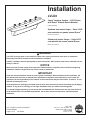
WARNING
Turn OFF electrical power to the electrical outlets, then unplug all electrical units prior to installation.
Electrical power MUST remain off until installation is complete.
Installer’s hardware must be appropriate for wall construction. Wall anchors must have a minimum pull-out
rating of 1,000 lb.
NOTICE
Make sure that all water supply lines have been flushed and then completely turned off before beginning
installation. Debris in supply lines can cause valves to malfunction.
IMPORTANT
Read this entire installation manual to ensure proper installation. When finished with the installation, file
this manual with the owner or maintenance department. Compliance and conformity to local codes and
ordinances is the responsibility of the installer. Product warranties may be found under “Products” on our
Web site at bradleycorp.com.
Separate parts from packaging and make sure all parts are accounted for before discarding any packaging
material. If any parts are missing, do not begin installation until you obtain the missing parts.
For standard height mounting, do not exceed the recommended 34" distance from the top of the lav deck
to the finished floor. To meet ADA requirements, the lav deck cannot exceed the 34" maximum height
dimension.

LVLD3 Installation
2 2/27/2020 Bradley • 215-1779 Rev. G: ECN 19-08-037A
Table of Contents
Components .................................................................................................................................................................................... 3
Supplies Required ........................................................................................................................................................................... 4
Dimensions .................................................................................................................................................................................. 4–5
Rough-Ins ........................................................................................................................................................................................ 6
Frame Mounting ............................................................................................................................................................................... 7
Faucet Box and Valve Mounting ...................................................................................................................................................... 8
Overflow Plug Assembly .................................................................................................................................................................. 8
Drain Assembly ............................................................................................................................................................................... 9
Faucets and Optional Soap Valve ................................................................................................................................................... 9
Bowl Mounting ............................................................................................................................................................................... 10
Strainer and P-Trap ....................................................................................................................................................................... 10
Adjust Temperature ........................................................................................................................................................................ 11
Trap Cover ..................................................................................................................................................................................... 11
Multi-Feed System Option ............................................................................................................................................................. 12
Cleaning and Maintenance ............................................................................................................................................................ 13
Table des matières
Composants .................................................................................................................................................................................. 15
Fournitures requises ...................................................................................................................................................................... 16
Dimensions .............................................................................................................................................................................. 16–17
Raccordements ............................................................................................................................................................................. 18
Montage du bâti ............................................................................................................................................................................. 19
Fixation du boîtier de batterie et de la vanne ................................................................................................................................ 20
Assemblage du bouchon de trop-plein .......................................................................................................................................... 20
Assemblage de l’écoulement ......................................................................................................................................................... 21
Robinets et vanne à savon en option ............................................................................................................................................ 21
Fixation de la vasque .................................................................................................................................................................... 22
Tamis et siphon en P ..................................................................................................................................................................... 22
Fair couler l'eau pour régler la température .................................................................................................................................. 23
Couvre-siphon ............................................................................................................................................................................... 23
Multi-Feed System Option ............................................................................................................................................................. 24
Nettoyage et entretien ................................................................................................................................................................... 25
Contenido
Componentes ................................................................................................................................................................................ 27
Materiales necesarios ................................................................................................................................................................... 28
Dimensiones ............................................................................................................................................................................ 28–29
Colocación de las tuberías empotradas ........................................................................................................................................ 30
Montaje de la estructura ................................................................................................................................................................ 31
Montaje de la caja de la llave y de la válvula ................................................................................................................................ 32
Conjunto de tapón contra desbordes ............................................................................................................................................ 32
Conjunto de desagüe .................................................................................................................................................................... 33
Llaves y válvula de jabón opcional ................................................................................................................................................ 33
Montaje de la palangana ............................................................................................................................................................... 34
Filtro y sifón en P .......................................................................................................................................................................... 34
Adjuste la temperatura .................................................................................................................................................................. 35
Cubierta del sifón .......................................................................................................................................................................... 35
Multi-Feed System Option ............................................................................................................................................................. 36
Limpieza y mantenimiento ............................................................................................................................................................. 37

Installation LVLD3
Bradley • 215-1779 Rev. G: ECN 19-08-037A 2/27/2020 3
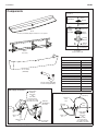
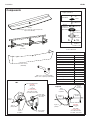
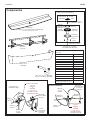
Components
Frame
(S17-377)
Access Panel
(186-2284)
Complete Hardware Prepack (S45-2473)
Frame Mounting Qty.
Washer, Square 9
Washer, Flat 1" O.D. 2
Bowl-To-Frame (S45-2481) Qty.
Screw, ¼-20 x ½" 3
Washer, Flat ⁵⁄₈" O.D. 3
Trap Cover (S45-2482) Qty.
Screw, 10-24 x ½" 6 (1 extra)
#10 Finishing Washer 6 (1 extra)
Trap Hook Bracket 1
Screw, 10-24 x
3
⁄8" 1
Washer, Flat
35
⁄64" O.D. 1
Bowl
Contact your Bradley Representative for color options
Chrome P-Trap (S29-094)
Plastic P-Trap (269-1697)
TMV Valve
(½" NPTM Outlet)
(S45-2701)
Hose Prepack
(S45-2730)
Supply Fittings
(Standard)
(S45-2512)
Supply Fittings
(Standard)
(S45-2513)
and
(S45-3004)
for Verge Faucets
S53-3100, S53-3300,
S53-3500, & S53-3700
and
(S45-3005)
for Verge Faucets
S53-3100, S53-3300,
S53-3500, & S53-3700
TMV Supply Connections
Plastic
Hose
Stainless Steel
Hose
Plastic
Hose
Complete Drain Prepack
(S45-2811)
O-Ring
(125-111)
Drain
Adapter
Packing
Washer
#10-24
Screw
Drain
Adapter
Prepack
(S45-2480)
Prepack
(S45-2810)
*Screw
Strainer
*Standoff, Hex,
SS #6-32 x 1"
*Screw #6-32
x 1-1/4" Pan
*Included in
Prepack S45-2778
Hose Prepack
(S45-2731)
Tempered Supply Connections
Plastic
Hose
Plastic
Hose
Stainless
Steel
Hose
Plastic
Hose

LVLD3 Installation
4 2/27/2020 Bradley • 215-1779 Rev. G: ECN 19-08-037A
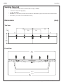
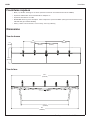
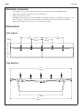
90"
(2286)
63¹¹/₁₆"
(1618)
Dimensions
(mm)
Top View
Front View
Supplies Required
• (11) ³⁄₈" fasteners and wall anchors (minimum pull-out rating of 1,000 lb)
• ½" hot/cold or tempered supply piping
• 1½" NPT drain piping
• OPTIONAL: (2) 110V GFCI protected electrical outlets for 100–120V AC plug-in transformers (for Bradley Faucets)
• Screen filter(s) as needed, if not included with faucet(s)
30"
(762)
15"
(381)
19½"
(495)
6½"
(165)
15"
(381)
30"
(762)
89½"
(2274)

Installation LVLD3
Bradley • 215-1779 Rev. G: ECN 19-08-037A 2/27/2020 5
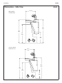
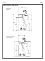
Dimensions – Side View
(mm)
34"
(864)
27"
(686)
6⁷/₈"
(175)
6⁷/₈"
(175)
ADA Standard
and TAS Height
Juvenile and TAS,
Grades 6 thru 12
16"
(406)
34½"
(876)
31"
(787)
24"
(610)
13"
(330)
31½"
(800)
14" (379)
14¹⁵/₁₆"
(379)

LVLD3 Installation
6 2/27/2020 Bradley • 215-1779 Rev. G: ECN 19-08-037A
C
B
A
D
E
16¹⁄₈"
(409)
H
32½"
(826)
5½"
(141)
13¾" (349)
A
B
B
B
Finished Floor
Approximate
Soap Battery
Box Location
Approximate
Soap Battery
Box Location
B
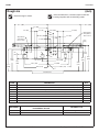
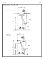
Standard rough-in shown.
RIM HEIGHT
VERTICAL HEIGHT ADJUSTMENTS
FOR CODES A–E and H
FIXTURE STYLE
34" None Standard Height, ADA, and TAS
31" Subtract 3" ADA Juvenile and TAS, Grades 6 thru 12
CODE DESCRIPTION QTY.
A 3⁄8" Bowl Anchors with a Minimum Pull-Out Force of 1,000 lb (reinforce walls at anchor points) 2
B 3⁄8" Frame Anchors with a Minimum Pull-Out Force of 1,000 lb (reinforce walls at anchor points) 9
H, C ½" Hot/Cold Supplies, Stub-Out 2" From Wall 1
D 110V GFI Protected Electrical Outlet (AC version only) 3
E 1½" NPT Drain, Stub-Out 2" from Wall 1
F #10 Anchors for Valve Bracket Installation 2
G #10 Anchors for Faucet Control Box Installation 4
J #10 Anchors for Soap Tank Installation 4
21" (533)
8¹⁄₈"
(208)
30³⁄₈" (772)
6¾" (171)
3¹⁄₈" (80)
3¹⁄₈" (80)
32¹⁄₈"
(817)
23½"
(598)
7½"
(190)
6¼"
(181)
Rough-Ins
(mm)
Areas marked with a crosshatch require sufficient
backing compliant with local building codes.
C
L
29³⁄₈"
(747)
27" (686)
23¼" (590)
D
D
G
G
G
G
G
G
B
B
B
B
J J
1"
(25)
3"
(76)
26¾"
(679)
21" (533)
4" (102)
F
F
1¾" (44)
J J
42⁷⁄₈" (1089) 42⁷⁄₈" (1089)
13⁵⁄₈" (346)
27½"
(698)
29¼" (743)
27" (686)
30³⁄₈" (772)

Installation LVLD3
Bradley • 215-1779 Rev. G: ECN 19-08-037A 2/27/2020 7
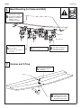
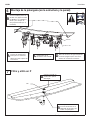
Frame Mounting
Support Backing Mounting
Height
"A" Dimension
Standard Height, ADA, and TAS 20" (508mm)
ADA, Juvenile and TAS, Grades
6 thru 12
17" (432mm)
Typical installation is shown. It may be necessary to repair the wall
after mounting. The fixture may not cover all of the wall modifications.
1
16"
(406mm)
centers
14"
(356mm)
A
Floor
Drywall
Drain, supplies and electrical box are
shown in their approximate locations.
Cut clearance holes in the plywood as
required.
NOTE: Plywood should equal the
thickness of the drywall (½" minimum).
B
Fasten plywood securely
to at least (4) studs.
A
Use
3
⁄8" fasteners and square washers provided to secure the
frame to plywood (9) places. Shim frame as necessary.
D
Shim the frame at anchor points to
ensure the offset bracket is straight.
Leave the top three screws loose
for bowl installation.
C
Minimum required to
pick up four studs and
vertical frame members
– 56" (1422mm) min.
56"
(1422mm)
Fasteners (supplied by installer)
to secure backing to studs

LVLD3 Installation
8 2/27/2020 Bradley • 215-1779 Rev. G: ECN 19-08-037A
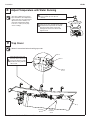
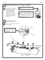
NONE Option
Plastic
Hose
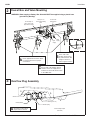
WARNING! Water supply to Battery Box Solenoid MUST be supplied using a plastic hose
(provided by Bradley).
Faucet Box and Valve Mounting
2
Mount the faucet boxes to the wall at
these approximate locations. Refer
to faucet instructions for proper
connections.
A
Secure the TMA valve
to the wall at the
location shown using
(2) #10 fasteners. See
rough-in section for
valve rough-in location.
B
Secure fittings to
wall or other at this
approximate location
Assemble the shutoff valves to
the hot and cold supplies. Attach
stainless steel 1/2" supply hoses
from the hot and cold shutoff valves
to the TMA valve.
C
Supply Hose to
Thermostatic Mixing
Valve
Thermostatic
Mixing Valve
Hot
Supply
Cold
Supply
Overflow Plug Assembly
3
Assemble overflow drain
cap to basin as shown.
A
O-Ring (125-111)
Overflow plug
Packing Washer
Overflow Plug Prepack
(S45-2812)
#10-24 Screw

Installation LVLD3
Bradley • 215-1779 Rev. G: ECN 19-08-037A 2/27/2020 9
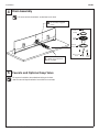
For ease of installation, leave the bowl laying on its back.
See Faucet and Soap installation instructions for assembly.
5
Faucets and Optional Soap Valve
For ease of drain installation, lay the bowl on its back.
4
Drain Assembly
Thread screw into drain
adapter until it becomes
fully engaged.
A
Thread the standoff onto
the now fully engaged
screw.
B
O-Ring
Drain
Adapter
Packing
Washer
#10-24
Screw
#6-32 x 1-1/4"
Screw
Standoff, Hex
SS #6-32 x 1"

LVLD3 Installation
10 2/27/2020 Bradley • 215-1779 Rev. G: ECN 19-08-037A
Strainer and P-Trap
7
Attach the strainer screw
to the strainer. Do not
overtighten.
A
Strainer
Thread the strainer screw
through the boss on the
drain adapter and secure
the strainer to the bowl.
B
Washer
¼"-20 Screw
Secure the bowl to the
wall using the 1" O.D.
flat washers (supplied by
Bradley), 3/8" fasteners
and 3/8" anchors
(supplied by installer).
B
Bowl Mounting (to Frame and Wall)
6
Press firmly on the back of
the bowl to seat the bowl
into the frame.
Tighten the top screw on
the frame.
A
Check to be sure the
basin is level.
C
Connect TMV or tempered
line supply connections.
See page 2 for supply
connection details.
D

Installation LVLD3
Bradley • 215-1779 Rev. G: ECN 19-08-037A 2/27/2020 11
Make all connections before installing trap cover.
Trap Cover
9
Hook
#10-24
Screw
Washer
#10-24
Flat Head
Screw
Finishing
Washer
Hang the trap cover onto
the hook, then secure the
trap cover with the screws
provided, starting with the
side screws.
A
Adjust Temperature with Water Running
H
C
A
Loosen Cap Screw about 1/4" (4-6
turns) and lift up cover (do not
remove).
B
Using cover, turn cartridge gently until
desired water temperature is reached.
Do not turn past stops as this may
damage unit. Push cover down and
tighten screw.
This valve is NOT factory preset.
Upon installation, the temperature
of this valve must be checked and
adjusted to ensure delivery of a
safe water temperature. Water
in excess of 110°F (43°C) may
cause scalding.
8

LVLD3 Installation
12 2/27/2020 Bradley • 215-1779 Rev. G: ECN 19-08-037A
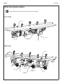
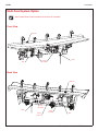
See the Multi-Feed System Installation Instructions for assembly.
Drain
Drain
Pump
Assembly
Pump
Assembly
Pump
Assembly
Plastic
Soap Line
Fill Puck
Tank
Tank
Multi-Feed System Option
Front View
Back View
Fill Puck

Installation LVLD3
Bradley • 215-1779 Rev. G: ECN 19-08-037A 2/27/2020 13
Cleaning and Maintenance for Evero
Material Description: Evero Natural Quartz Material is made from a blend of acrylic modified bio-based polyester resin, natural
quartz and other materials and is resistant to chemicals, stains, burns and impact. Surface damage can be easily repaired with
everyday cleansers or fine grit abrasives.
Routine Cleaning: For regular cleaning, use standard commercial or household products such as Simple Green®, Creamy
Cleanser brand, Formula 409
®
or Windex
®
.
Stubborn Stains: Remove tough stains, with non abrasive cleaners and pads such as a white Scotch Brite
®
pad and Lysol
®
.
Special Situations for Evero Material
Hard Water Deposits: Remove hard water deposits with a mild solution of vinegar and water. Always rinse the unit thoroughly
after cleaning.
Restoring the surface: Refresh and restore the rich surface with one of the following:
Geo Series: Color enhancer such as Tenax
®
Ager
Pearl Series: Impregnating sealer such as DryTreat Stain - Proof Original™ or Miracle Sealants 511 Impregnator
NOTICE! Do not use strong acid or alkaline chemicals and cleansers to clean Evero. If these chemicals
come in contact with the surface, wipe them off immediately and rinse with soapy water. Avoid
contact with harsh chemicals such as paint remover, bleach, acetone, etc. Avoid contact with hot
pans and objects.
Repair Kits: Evero repair kits are available. Contact your Bradley representative or distributor for part numbers and pricing.
Repair kits are made to order and have a shelf life of 30 days.
Cleaning and maintenance instructions for stainless steel
Material Description: Stainless steel is extremely durable, and maintenance is simple and inexpensive. Proper care, particularly
under corrosive conditions, is essential. Always start with the simplest solution and work your way toward the more complicated.
Routine cleaning: Daily or as often as needed use a solution of warm water and soap, detergent, or ammonia. Apply the cleaning
solution per the manufacturer’s instructions and always use a soft cloth or sponge to avoid damaging the finish.
Stubborn Stains: To remove stains from stainless steel use a stainless steel cleaner and polish such as Ball
®
stainless steel
cleaner or a soft abrasive. Always follow the manufacturer’s instructions and apply in the same direction as the polish lines.
NOTICE! Never use ordinary steel wool or steel brushes on stainless steel. Always use stainless steel wool
or stainless steel brushes.
Special Situations for Material
Fingerprints and Smears: To remove fingerprints or smears use a high quality stainless steel cleaner and polish in accordance
with the manufacturer’s instructions. Many of these products leave a protective coating that helps prevent future smears and
fingerprints.
Grease and Oil : To remove grease and oil use a quality commercial detergent or caustic cleaner. Apply in accordance to the
manufacturer’s instructions and in the direction of the polish lines.
Precautions: Avoid prolonged contact with chlorides (bleaches, salts), bromides (sanitizing agents), thiocyanates (pesticides,
photography chemicals, and some foods), and iodides on stainless steel equipment, especially if acid conditions exist.
NOTICE! Do not permit salty solutions to evaporate and dry on stainless steel.
The appearance of rust streaks on stainless steel leads to the belief that the stainless steel is rusting. Look for the actual source
of the rust in some iron or steel particles which may be touching, but not actually a part of the stainless steel structure.
NOTICE! Strongly acidic or caustic cleaners may attack the steel, causing a reddish film to appear. The use
of these cleaners should be avoided.
Brand Names: Use of brand names is intended only to indicate a type of cleaner. This does not constitute an endorsement, nor
does the omission of any brand name cleaner imply its inadequacy. Many products named are regional in distribution, and can be
found in local supermarkets, department and hardware stores, or through your cleaning service. It is emphasized that all products
should be used in strict accordance with package instructions.
Evero is a unique cast material. Aggregate flow and distribution as well as shades of color can vary from
product to product creating natural characteristics.

LVLD3 Installation
14 2/27/2020 Bradley • 215-1779 Rev. G: ECN 19-08-037A
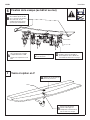
AVERTISSEMENT
Couper l’alimentation électrique des prises de courant, puis débrancher tous les appareils électriques avant
de procéder à l’installation. L’alimentation électrique doit IMPÉRATIVEMENT être coupée jusqu’à la fin de
l’installation.
La visserie de l’installateur doit être adaptée à la nature du mur. Les ancrages muraux doivent avoir une
résistance nominale à l’arrachement d’au moins 1000 lb (4,45 kN).
AVIS
S’assurer que toutes les conduites d’arrivée d’eau ont été purgées puis correctement fermées avant de
commencer l’installation. La présence de débris dans les conduites peut causer un mauvais fonctionnement
des vannes.
IMPORTANT
Veiller à lire ce manuel en entier pour assurer une installation correcte. Lorsque l’installation est terminée,
remettre ce manuel au propriétaire ou au service d’entretien. La mise en conformité et le respect de la
réglementation en vigueur relèvent de la responsabilité des installateurs. Les garanties de produit peuvent
être trouvées sous «Products» sur notre site Web à www.bradleycorp.com
Déballer les pièces et s’assurer qu’elles sont toutes présentes avant de jeter les emballages. Le cas échéant,
ne pas commencer l’installation avant d’avoir obtenu toutes les pièces manquantes.
Pour les poses de hauteur standard, ne pas dépasser la distance conseillée de 34" (864mm) entre le dessus
du rebord de lavabo et le sol fini. Pour être conforme aux exigences ADA, le rebord de lavabo ne devra pas
dépasser la hauteur maximale de 34" (864mm).

Installation LVLD3
Bradley • 215-1779 Rev. G: ECN 19-08-037A 2/27/2020 15
Composants
Bâti
(S17-377)
Panneau d’accès
(186-2284)
Trousse de quincaillerie complète (S45-2473)
Montage du bâti Qté
Rondelle carrée 9
Rondelle plate 1" dia. ext. 2
Vasque-bâti (S45-2481) Qté
Vis ¼-20 x ½" 3
Rondelle plate ⁵⁄₈" dia. ext. 3
Couvre-siphon (S45-2482) Qté
Vis 10-24 x ½" 6 (1 en plus)
Rondelle de finition n° 10 6 (1 en plus)
Crochet support de siphon 1
Vis 10-24 x
3
⁄8" 1
Rondelle plate
35
⁄64" dia. ext. 1
Vasque
Se renseigner sur le choix de couleurs auprès du
représentant Bradley.
Siphon en P chromé (S29-094)
Siphon en P en plastique (269-1697)
Vanne TMV
(Sortie ½" NPTM)
(S45-2701)
Trousse
tuyaux
(S45-2731)
Trousse tuyaux
(S45-2730)
Tuyau en
plastique
Tuyau en
plastique
Tuyau en
plastique
Tuyau en
plastique
Tuyau en
plastique
Tuyau
en acier
inoxydable
Tuyau
en acier
inoxydable
Trousse d’écoulement
complète (S45-2811)
Joint torique
(125-111)
Adaptateur
d’écoulement
Bague
d’étanchéité
Vis n°
10-24
Trousse
adaptateur
d’écoulement
(S45-2480)
Trousse
(S45-2810)
* Vis
Tamis
* Entretoise hexa,
inox #6-32 x 1"
* Vis cylindrique
bombée
n°6-32 x 1-1/4"
* Inclus dans la
trousse S45-2778
Raccords d’alimentation
(Standard)
(S45-2512)
Raccords d’alimentation
(Standard)
(S45-2513)
et
(S45-3004)
for Verge Faucets
S53-3100, S53-3300,
S53-3500, & S53-3700
et
(S45-3005)
for Verge Faucets
S53-3100, S53-3300,
S53-3500, & S53-3700
Raccordements d’alimentation
tempérée
Raccordements d’alimentation
TMV

LVLD3 Installation
16 2/27/2020 Bradley • 215-1779 Rev. G: ECN 19-08-037A
Dimensions
Vue de dessus
Vue de face
Fournitures requises
• Onze (11) chevilles d’ancrage et vis de 3/8" (résistance nominale à l’arrachement d’au moins 1000 lb)
• Tuyauterie d’alimentation d’eau chaude/froide ou tempérée ½"
• Tuyauterie d’écoulement 1½" NPT
• EN OPTION : Deux (2) prises électriques 110 V à disjoncteur à protection DDFT (GFCI) pour transformateur à fiche
100–120 VCA (pour robinets Bradley)
• Filtre(s) à tamis selon les besoins, si non fourni(s) avec le(s) robinet(s)
30"
(762mm)
15"
(381mm)
19½"
(495mm)
6½"
(165mm)
15"
(381mm)
30"
(762mm)
90"
(2286mm)
63¹¹/₁₆"
(1618mm)
89½"
(2274mm)

Installation LVLD3
Bradley • 215-1779 Rev. G: ECN 19-08-037A 2/27/2020 17
Dimensions — Vue de côté
Hauteur ADA
standard et TAS
Enfant et TAS,
6e à 12e années
34"
(864mm)
27"
(686mm)
6⁷/₈"
(175mm)
16"
(406mm)
34½"
(876mm)
14¹⁵/₁₆"
(379mm)
6⁷/₈"
(175mm)
31"
(787mm)
24"
(610mm)
13"
(330mm)
31½"
(800mm)
14¹⁵/₁₆"
(379mm)

LVLD3 Installation
18 2/27/2020 Bradley • 215-1779 Rev. G: ECN 19-08-037A
Plancher fini
Raccordements standard
représentés.
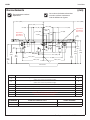
HAUTEUR
DU REBORD
AJUSTEMENTS DE LA HAUTEUR
POUR LES CODES A–E et H
TYPE D’APPAREIL
34" (864mm) Aucun Hauteur standard, ADA et TAS
31" (787mm) Retrancher 3" (76mm) ADA, enfant et TAS, 6e à 12e années
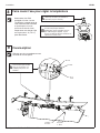
CODE DESCRIPTION QTÉ
A
Chevilles d’ancrage de vasque de 3⁄8" d’une résistance minimale à l’arrachement de 1 000 lb
(renforcer les murs aux points d’ancrage)
2
B
Chevilles d’ancrage de bâti de 3⁄8" d’une résistance minimale à l’arrachement de 1 000 lb
(renforcer les murs aux points d’ancrage)
9
H, C Arrivées d’eau chaude/froide de ½", tubulure à 2" (51mm) du mur 1
D Prise électrique 110 V à disjoncteur à protection DDFT (GFI) (version courant secteur seulement) 3
E Écoulement 1½" NPT, tubulure à 2" (51mm) du mur 1
F Chevilles d’ancrage n° 10 pour l’installation du support de vanne 2
G #10 Anchors for Faucet Control Box Installation 4
J #10 Anchors for Soap Tank Installation 4
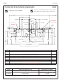
Raccordements
(mm)
Les surfaces hachurées nécessitent
un renfort suffisant conforme au
code du bâtiment en vigueur.
C
B
A
D
E
16¹⁄₈"
(409)
H
32½"
(826)
5½"
(141)
13¾" (349)
A
B
B
B
Approximate
Soap Battery
Box Location
Approximate
Soap Battery
Box Location
B
21" (533)
8¹⁄₈"
(208)
30³⁄₈" (772)
6¾" (171)
3¹⁄₈" (80)
3¹⁄₈" (80)
32¹⁄₈"
(817)
23½"
(598)
7½"
(190)
6¼"
(181)
C
L
29³⁄₈"
(747)
27" (686)
23¼" (590)
D
D
G
G
G
G
G
G
B
B
B
B
J J
1"
(25)
3"
(76)
26¾"
(679)
21" (533)
4" (102)
F
F
1¾" (44)
J J
42⁷⁄₈" (1089) 42⁷⁄₈" (1089)
13⁵⁄₈" (346)
27½"
(698)
29¼" (743)
27" (686)
30³⁄₈" (772)

Installation LVLD3
Bradley • 215-1779 Rev. G: ECN 19-08-037A 2/27/2020 19
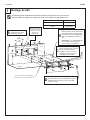
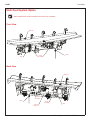
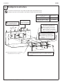
Montage du bâti
Hauteur de pose des renforts Dimension « A »
Hauteur standard, ADA et TAS 20" (508mm)
ADA, enfant et TAS, 6e à 12e
années
17" (432mm)
Installation typique représentée. Il peut être nécessaire de réparer le mur après la pose.
Il est possible que l’appareil ne masque pas toutes les modifications apportées au mur.
1
16"
(406mm)
entre
centres
14"
(356mm)
A
Plancher
Cloison
sèche
Attacher le contreplaqué
solidement à au moins
quatre (4) montants.
A
Minimum requis pour
couvrir quatre montants
et éléments d’ossature
verticaux – 56"
(1422mm) min.
56"
(1422mm)
Visserie (fournie par l’installateur)
pour attacher le renfort aux montants
L’écoulement, les arrivées et le
boîtier électrique sont représentés à
leurs emplacements approximatifs.
Découper des trous de dégagement
dans le contreplaqué comme il se
doit.
REMARQUE : Le contreplaqué doit
être de même épaisseur que la
cloison sèche (½" minimum).
B
Placer des cales sous le bâti aux
points d’ancrage pour s’assurer
que la console de support
est droite. Laisser les trois vis
supérieures desserrées pour
l’installation de la vasque.
C
Utiliser des vis de 3⁄8" et des rondelles carrées
pour attacher le bâti au contreplaqué à neuf (9)
emplacements. Placer des cales sous le bâti
comme il se doit.
D

LVLD3 Installation
20 2/27/2020 Bradley • 215-1779 Rev. G: ECN 19-08-037A
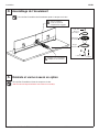
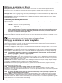
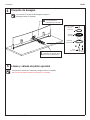
Assemblage du bouchon de trop-plein
3
Monter le capuchon de
trop-plein à la vasque
comme sur l’illustration.
A
Joint torique (125-111)
Bouchon de trop-plein
Bague d’étanchéité
Trousse bouchon de
trop-plein (S45-2812)
Vis n° 10-24
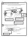
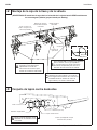
AVERTISSEMENT! L’arrivée d’eau de l’électrovanne du boîtier de batterie doit IMPÉRATIVEMENT se
faire au moyen d’un tuyau en plastique (fourni par Bradley).
Fixation du boîtier de robinet et de la vanne
2
Monter les boîtiers de robinet au mur
à ces emplacements approximatifs.
Voir les raccordements corrects dans
les instructions du robinet.
A
Fixer la vanne TMA au mur à
l’emplacement indiqué avec deux
(2) vis n° 10. Voir l’emplacement des
raccordements de vanne à la section
Raccordements.
B
Fixer les raccords au mur
ou autre à cet emplacement
approximatif
Monter les robinets d’arrêt sur les
arrivées d’eau chaude et d’eau froide.
Monter les tuyaux d’arrivée de 1/2" en
acier inoxydable entre les robinets d’arrêt
d’eau chaude et froide et la vanne TMA.
C
Tuyau d’arrivée
vers le mitigeur
thermostatique
Mitigeur
thermostatique
Arrivée d’eau
chaude
Arrivée
d’eau
froide
AUCUNE option
Tuyau en
plastique
La page charge ...
La page charge ...
La page charge ...
La page charge ...
La page charge ...
La page charge ...
La page charge ...
La page charge ...
La page charge ...
La page charge ...
La page charge ...
La page charge ...
La page charge ...
La page charge ...
La page charge ...
La page charge ...
La page charge ...
-
 1
1
-
 2
2
-
 3
3
-
 4
4
-
 5
5
-
 6
6
-
 7
7
-
 8
8
-
 9
9
-
 10
10
-
 11
11
-
 12
12
-
 13
13
-
 14
14
-
 15
15
-
 16
16
-
 17
17
-
 18
18
-
 19
19
-
 20
20
-
 21
21
-
 22
22
-
 23
23
-
 24
24
-
 25
25
-
 26
26
-
 27
27
-
 28
28
-
 29
29
-
 30
30
-
 31
31
-
 32
32
-
 33
33
-
 34
34
-
 35
35
-
 36
36
-
 37
37


Bradley Verge LVLD Series Guide d'installation
- Catégorie
- Articles sanitaires
- Taper
- Guide d'installation
- Ce manuel convient également à
dans d''autres langues
Documents connexes
-
Bradley Express ELX Series Guide d'installation
-
-
-
-
-
-
-
-
-
