Vulcan-Hart ML-152031 Le manuel du propriétaire
- Taper
- Le manuel du propriétaire

INSTALLATION &
OPERATION MANUAL
FORM F37523 Rev C (4-20)
ELECTRIC COUNTER
CONVECTION
STEAMERS
MODELS
C24EA3
ML-136037 208/240V 1/3 9.25KW PRO
ML-136037 C24EA3 208/240V 9.25KW PRO
ML-136038 C24EA5 208/240V 15.75KW PRO
ML-136044 480V PH 1/3 9.25KW PRO
ML-152049 208/240V PH 1/3 8.5KW PLUS
ML-152050 480V PH 1/3 8.5KW PLUS
ML-152057 208/240V PH 1/3 8.5KW PLUS/SONIC
ML-152058 208/240V PH 1/3 9.25KW PRO/SONIC
ML-152059 208/240V PH 3 8.5KW LWE/SONIC
ML-152060 480V PH 1/3 8.5KW PLUS / SONIC
ML-152061 480V PH 1/3 9.25KW PRO / SONIC
ML-152062 480V PH 3 8.5KW LWE / SONIC
C24EA5
ML-136038 208/240V 15KW PLUS
ML-136047 480V PH 1/3 15.75KW PRO
ML-152031 208/240 or 480V PH 3 15KW LWE
ML-152051 208/240V PH 1/3 15KW PLUS
ML-152052 480V PH 1/3 15KW PLUS
ML-152063 208/240V PH 1/3 15KW PLUS/SONIC
ML-152064 208/240V PH 1/3 15.75KW PRO/SONIC
ML-152065 208/240V PH 3 15KW LWE/SONIC
ML-152066 480V PH 1/3 15KW PLUS / SONIC
ML-152067 480V PH 1/3 15.75KW PRO / SONIC
ML-152068 480V PH 3 15KW LWE / SONIC
For additional information on Vulcan or to locate an authorized parts
and service provider in your area, visit our website at www.vulcanequipment.com
VULCAN
DIVISION OF ITW FOOD EQUIPMENT GROUP, LLC
WWW.VULCANEQUIPMENT.COM
3600 NORTH POINT BLVD.
BALTIMORE, MD 21222

— 2 —
C24EA SERIES ELECTRIC COUNTER CONVECTION STEAMERS
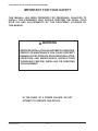
IMPORTANT FOR YOUR SAFETY
THIS MANUAL HAS BEEN PREPARED FOR PERSONNEL QUALIFIED TO
INSTALL THIS EQUIPMENT, WHO SHOULD PERFORM THE INITIAL FIELD
START-UP AND ADJUSTMENTS OF THE EQUIPMENT COVERED BY
THIS MANUAL.
WARNING
IMPROPER INSTALLATION, ADJUSTMENT, ALTERATION,
SERVICE OR MAINTENANCE CAN CAUSE PROPERTY
DAMAGE, INJURY OR DEATH. READ THE INSTALLATION,
OPERATING AND MAINTENANCE INSTRUCTIONS
THOROUGHLY BEFORE INSTALLING OR SERVICING
THIS EQUIPMENT.
IN THE EVENT OF A POWER FAILURE, DO NOT
ATTEMPT TO OPERATE THIS DEVICE.
© VULCAN, 2020

— 3 —
C24EA SERIES ELECTRIC COUNTER CONVECTION STEAMERS
TABLE OF CONTENTS
IMPORTANT FOR YOUR SAFETY ..................................................................................................2
INSTALLATION, OPERATION, AND CARE OF MODEL C24EA SERIES STEAMERS ...............5
General ..........................................................................................................................................5
Professional Powersteam Option ..................................................................................................5
Energy Star Steamer Option .........................................................................................................5
Sonicsafe Scale Prevention Option ...............................................................................................5
Installation .....................................................................................................................................5
Unpacking ......................................................................................................................................5
Installation Codes And Standards ................................................................................................6
Location .........................................................................................................................................6
Leveling Feet .................................................................................................................................6
Leveling .........................................................................................................................................6
Anchoring Steamer ........................................................................................................................6
Stacking Stand ..............................................................................................................................6
Electrical Connection .....................................................................................................................7
Plumbing Connections ...................................................................................................................8
Water Requirements ................................................................................................................8
Water Treatment ......................................................................................................................8
Water Supply Connection ........................................................................................................8
Drain Connections .........................................................................................................................8
Vent Hood ......................................................................................................................................9
OPERATION ....................................................................................................................................10
Controls .......................................................................................................................................10
Main Power Switch Light .......................................................................................................10
Ready Light ............................................................................................................................10
Cooking Light .........................................................................................................................10
Timer ......................................................................................................................................10
Start Up .......................................................................................................................................10
Operation .....................................................................................................................................11
Main Power Switch ................................................................................................................11
Timer ......................................................................................................................................11
Ready Light ............................................................................................................................11
Cooking Light .........................................................................................................................11
Sonicsafe Light ......................................................................................................................11
Call Service Light ...................................................................................................................11
Preheating ...................................................................................................................................11
Steaming .....................................................................................................................................11
Shutdown .....................................................................................................................................11
Extended Shutdown ....................................................................................................................11

— 4 —
C24EA SERIES ELECTRIC COUNTER CONVECTION STEAMERS
CLEANING .......................................................................................................................................12
Cooking Compartment Drain .......................................................................................................12
Draining Generator ......................................................................................................................12
Compartment ...............................................................................................................................12
Door Gasket ................................................................................................................................12
Leave Compartment Door Open .................................................................................................12
STAINLESS STEEL EQUIPMENT CARE AND CLEANING .........................................................13
Enemies Of Stainless Steel .........................................................................................................13
So What Does All This Mean? Don’t Despair! ............................................................................13
Review .........................................................................................................................................13
MAINTENANCE ...............................................................................................................................14
Water Treatment System .............................................................................................................14
Removal Of Lime Scale Deposits ................................................................................................14
Items Required (Not Provided): .............................................................................................14
Professional Unit (Automatic Drain) .......................................................................................14
Door Gasket ................................................................................................................................15
Draining Steam Generator ...........................................................................................................15
COOKING HINTS ............................................................................................................................16
Preparation ..................................................................................................................................16
Frozen Food Items .................................................................................................................16
Acceptable Pan Sizes ............................................................................................................16
Cooking Guidelines .....................................................................................................................16
Products To Be Cooked In Solid Pans .........................................................................................17
Products To Be Cooked In Perforated Pans ................................................................................18
TROUBLESHOOTING ....................................................................................................................20
SERVICE AND PARTS INFORMATION.........................................................................................21
NOTES..............................................................................................................................................22
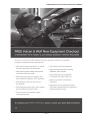
FREE VULCAN & WOLF NEW EQUIPMENT CHECKOUT .........................................................23
PROTECT YOUR INVESTMENT ...................................................................................................24

— 5 —
C24EA SERIES ELECTRIC COUNTER CONVECTION STEAMERS
INSTALLATION, OPERATION AND CARE OF
MODEL C24EA SERIES STEAMERS
PLEASE KEEP THIS MANUAL FOR FUTURE USE
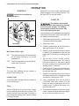
GENERAL
Vulcan convection steamers are produced with
quality workmanship and materials. Proper
installation, usage and maintenance will result
in many years of satisfactory performance. It is
suggested that you thoroughly read this entire
manual and carefully follow all the instructions
provided.
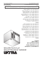
The C24EA3 and C24EA5 convection steamers
are single compartment, electric, pressureless
steam cookers with an internal electric steam
generator that maintains water temperature at
approximately 195°F.
Model C24EA3 can accommodate three 2 1/2"
deep (6.4 cm) steam pans. Model C24EA5
can accommodate fi ve 2 1/2"deep (6.4 cm)
steam pans. The C24EA3 and C24EA5 electric
convection steamers are designed for cooking
vegetables, eggs, and other foods, in commercial
kitchens. The steamer has a 0 to 60-minute
timer. The steamers are designed for countertop
installation or on optional stands available from
your Vulcan dealer.
PROFESSIONAL POWERSTEAM
OPTION
Vulcan’s patented super-heated steam option
cooks at 235°F compared to conventional
atmospheric steamers at 212°F.
ENERGY STAR STEAMER OPTION
Smart Steam Sensors continuously measure
and regulate steam temperature and production,
reducing scale buildup, fi lter changes and excess
steam/water (up to 90%). Utility rebate qualifi ed
where off ered.
SONICSAFE SCALE PREVENTION
OPTION
Sound waves create millions of microscopic
bubbles inside the steam generator, causing
powerful vacuum energy that prevents scale from
attaching to the walls of the steamer. The control
panel is equipped with indicator lights showing
that the SonicSafe system is in operation and
to indicate if there is a problem and service is
needed.
De-lime once a quarter instead of monthly, and
change your carbon fi lter just once a year.
INSTALLATION
Before installing, verify that the electrical supply
agrees with the specifi cations on the data plate
located on the back panel. If the supply and
equipment requirements do not agree, do not
proceed with the installation. Contact your dealer
or Vulcan immediately
208/240 units are shipped pre wired for 208/60/3.
240v & single phase operation require changes
to the heater connection 240/60/3, 240/60/1
and 208/60/1. This unit will operate at 60Hz or
50Hz. 480 volt units are shipped confi gured for
480/60/3.
LWE units are only available for 3 phase
operation.
UNPACKING
This steamer was inspected before leaving the
factory. The transportation company assumes full
responsibility for safe delivery upon acceptance
of the shipment. Immediately after unpacking,
check for possible shipping damage. If steamer
damage is found, save the packaging material
and contact the carrier within 5 days of delivery.

— 6 —
C24EA SERIES ELECTRIC COUNTER CONVECTION STEAMERS
INSTALLATION CODES
AND STANDARDS
In the United States, the Vulcan steamer must
be installed in accordance with:
1. State and local codes.
2. National Electrical Code (ANSI/NFPA No.70,
latest edition) available from the National
Fire Protection Association, Batterymarch
Park, Quincy, MA 02269.
3. Vapor Removal from Cooking Equipment,
(NFPA-96, latest edition) available from
NFPA.
In Canada, the Vulcan steamer must be installed
in accordance with:
1. Local codes.
2. Canadian Electrical Code (CSA C22.2 No.3,
latest edition) available from the Canadian
Standards Association, 5060 Spectrum Way,
Mississauga, Ontario, Canada L4W 5N6.
LOCATION
Allow space for plumbing and electrical
connections. Minimum clearance is 6" (15.2
cm) on the back for proper air circulation. Allow
adequate access for operating and servicing the
steamer (36" at the front of the steamer, 15" (38
cm) above the steamer and 18" (45.7 cm) on
right side of steamer).
LEVELING FEET
This steamer is shipped with four 2" leveling
feet. Optional 4" leveling feet are available.
The 2" feet can be removed and the optional 4"
feet can be threaded into holes on the bottom
of the unit.
LEVELING
Using a spirit level or pan of water in the bottom
of the steamer, adjust the leveling feet or the
feet on the adjustable legs to level the steamer
side to side with a slight tilt front to back to
allow for proper cavity draining. After the drain
is connected, check for level by pouring water
onto the fl oor of the compartment. All water
should drain through the opening at the back
of the compartment cavity.
Steamer must be installed level
side to side with a slight tilt front to back
to allow for proper draining.
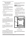
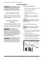
ANCHORING STEAMER
1. Place steamer in the desired location on
the countertop and mark four corners.
Remove the steamer and drill 1/2" holes as
indicated in Figure 1.
2. Apply a bead of RTV or other NSF approved
sealant around the bottom edge of the
steamer. If anchoring the steamer, this
bottom seal is necessary to meet NSF
requirements.
3. Set steamer on countertop and bolt down
securely with 3/8" by 16" bolts (not supplied).
Figure 1
STACKING STAND
Instruction to install convection steamers on
stacking stand are included with the stacking
stand.

— 7 —
C24EA SERIES ELECTRIC COUNTER CONVECTION STEAMERS
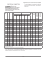
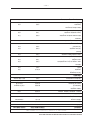
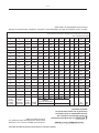
ELECTRICAL CONNECTION
Electrical and
grounding connections must comply
with the applicable portions of the
National Electrical Code and/or other
local electrical codes.
The wiring diagram is located on the right side
panel as you face the steamer. This steamer is
hard wired.
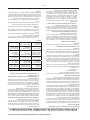
Total
KW
Volts Hz Ph KW Per Phase Rated Amps Single
Phase
Circuit
Size
Amps
Fuse
Size or
Circuit
Breaker
Size*
(Amps)
90°C
Copper
Min.
Wire
Size
3-Phase Amps Per Line
L1-L2 L2-L3 L3-L1 L1 L2 L3
8.5 208 50/60 1 40.87 60 60 8
8.5 240 50/60 1 35.42 50 50 8
8.5 208 50/60 3 4.25 2.12 2.12 26.54 26.54 17.70 35 35 10
8.5 240 50/60 3 2.83 2.83 2.83 20.50 20.50 20.50 30 25 10
8.5 480 50/60 3 2.83 2.83 2.83 10.30 10.30 10.30 15 15 16
9.25 208 50/60 1 43.57 60 60 6
9.25 240 50/60 1 38.54 50 50 8
9.25 208 50/60 3 4.25 2.69 2.12 26.54 28.88 20.04 35 35 10
9.25 240 50/60 3 2.83 3.58 2.83 20.45 23.15 23.15 30 30 10
9.25 480 50/60 3 2.83 3.58 2.83 10.21 11.57 11.57 15 15 16
15 208 50/60 1 72.12 90 90 4
15 240 50/60 1 62.50 75 75 6
15 208 50/60 3 7.50 3.75 3.75 46.84 46.84 31.23 60 60 6
15 240 50/60 3 5.00 5.00 5.00 36.08 36.08 36.08 50 50 8
15 480 50/60 3 5.00 5.00 5.00 18.04 18.04 18.04 25 25 14
15.75 208 50/60 1 74.82 90 90 4
15.75 240 50/60 1 65.63 80 80 4
15.75 208 50/60 3 7.50 4.31 3.75 46.84 49.18 33.57 60 60 6
15.75 240 50/60 3 5.00 5.75 5.00 36.08 38.79 38.79 50 50 8
15.75 480 50/60 3 5.00 5.75 5.00 18.04 19.40 19.40 25 25 14
2002 National Electric Code
*Dual Element Time-Delay Fuse or Inverse Time Circuit Breaker
Circuit Size (minimum) & Fuse/Circuit Breaker Size (maximum) compiled in accordance with the
National Electrical Code (ANSI/NFPA 70), 2002 Edition.

— 8 —
C24EA SERIES ELECTRIC COUNTER CONVECTION STEAMERS
PLUMBING CONNECTIONS
Plumbing connections must
comply with applicable sanitary, safety
and plumbing codes.
Water Requirements
Proper water quality can improve the taste of
the food prepared in the steamer, reduce liming
in the steam generator and extend equipment
life. Water conditions vary from one location
to another. Ask your municipal water supplier
for details about your local water supply prior
to installation. Presence of sediment, silica,
excess chlorides or other dissolved solids may
lead to a recommendation for alternate form(s)
of water treatment. Test the water with the test
strip included with the steamer. Other factors
aff ecting steam generation are iron content,
amount of chloridation and dissolved gases.
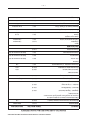
Water Treatment
A local water treatment specialist should be
consulted before installation of steam generating
equipment.
Supply Pressure 20 psig fl owing -
60 psig static
Hardness No more than 3 grains
Silica less than 13 ppm
Total Chlorine less than 0.5 ppm
PH range 6.5 - 8
Undissolved Solids less than 5 microns
*17.1 ppm = 1 grain of hardness
If the water supply fails to meet these standards,
it will be necessary to install a water conditioner
or scale & chlorine reduction fi lter system on
the generator water feed. The use of strainers
or particle fi lters will not remove minerals from
the water.
Water Supply Connection
Connect the treated cold water supply line to the
3/4" (19 mm) (male hose thread) inlet. Connect
the untreated cold water supply line to the
3/4" (19 mm) (male hose thread) inlet marked
UNTREATED WATER.
Do not over tighten water
connections. Over tightening the hose
connections will damage the water valve.
Turn hose connection by hand till snug
and then tighten with pliers 2/3 of a turn.
Check for leaks.
If water lines move during water
fi ll valve operation then a water hammer
arrestors must be added.
A water fi lter system is recommended for the
water supply line going to the treated water
inlet. Follow the recommendations for use and
installation instructions shipped with the water
fi lter. If a water fi lter is not installed, the steam
generator warranty may be limited.
A manual shutoff valve must be provided in a
convenient location near the steamer.
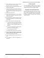
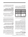
DRAIN CONNECTIONS
The drain connection (Figure 2) must be 1 1/2"
(38 mm) down, preferably with one elbow only,
maximum length of 6' and piped to an open gap
type drain.
In order to avoid any back
pressure in the steamer, do not make a
solid connection to any drain. FAILURE TO
DO SO CAN DAMAGE THE STEAMER AND
VOIDS THE WARRANTY.
A vent must be installed to avoid creating a
vacuum or pressure in the cooking chamber.
If two steamers are stacked they must have
independent drains and vents.

— 9 —
C24EA SERIES ELECTRIC COUNTER CONVECTION STEAMERS
Figure 2
VENT HOOD
Local codes may require the steamer to be
located under an exhaust hood. Information on
the construction and installation of ventilating
hoods may be obtained from Vapor Removal
from Cooking Equipment, NFPA standard No.
96 (latest edition).
Temperatures in the drain can briefl y reach as
high as 212°F (100°C). Local codes may require
that the temperature of drain water be no greater
than 140°F (60°C). Some provision for lowering
the water temperature must be provided by the
user or installer to meet this code requirement.

— 10 —
C24EA SERIES ELECTRIC COUNTER CONVECTION STEAMERS
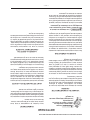
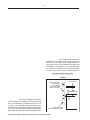
CONTROLS
Controls for SonicSafe are
shown in Figure 3.
Sonic
Safe
Call
Service
SonicSafe
Main Power Switch Light
ON The steam generator will automatically
fi ll and begin heating to the preset
temperature.
OFF The steam generator will drain, switch
power light will turn off .
Ready Light
The ready light indicates that the steamer is
ready for the cooking cycle.
Cooking Light
The cooking light indicates that the steamer is
in the cooking cycle.
Timer
Set the cooking time (0 to 60 minutes). Steam
cooking will begin when the door is closed. The
cooking cycle will be interrupted if the door is
open during the cooking cycle; resume cooking
by closing the door.
When done, a buzzer sounds and steam stops
being supplied to the cooking chamber. Turn
the timer OFF to stop the buzzer.
START UP
The steamer and its parts
are hot. Use care when operating, cleaning
or servicing the steamer. The cooking
compartment contains live steam. Stay
clear while opening the door.
Once the steamer is installed and all mechanical
connections have been made, thoroughly test
the steamer before operation.
1. Check that proper water, drain, and electrical
connections have been made.
2. Open water valve.
3. Press the power switch to the ON position.
Wait approximately 8-10 minutes.
4. Open the door and observe that no steam
is entering the compartment, and that the
ready light is ON and the cooking light is
OFF.
5. Set the timer to the 5 minute position.
Close the compartment door. The cooking
light should now be lit and steam should
be heard entering the compartment. Wait
approximately 2-3 minutes.
6. Check drain line to ensure that water from
the cold-water condensate valve is fl owing
through the drain line.
7. Open the compartment door and observe
that steam supply to the compartment stops
and that the cooking light is OFF.
8. Close compartment door and let cooking
cycle fi nish. When timer returns to 0, the
buzzer will sound, signaling the end of the
cooking cycle. To silence the buzzer, turn
the timer dial to OFF.
9. To shut down the steamer, turn off the power
switch. Leave the compartment doors slightly
open to allow the inside to dry out.
OPERATION
Figure 3

— 11 —
C24EA SERIES ELECTRIC COUNTER CONVECTION STEAMERS
OPERATION
Main Power Switch
ON The power light will illuminate, and the
generator will automatically fi ll and begin
heating to the preset temperature.
OFF The power light will turn off , and the
generator will drain.
Timer
Set to the desired cooking time, or set to the
constant position. Timer range is 0-60 minutes.
When the timer reaches 0, the buzzer sounds and
steam stops entering the cooking compartment.
Turn the timer to the off position to stop the
buzzer. If constant steam is selected, the steamer
will steam continuously, and the timer will not
time out.
Ready Light
The ready light indicates that the steamer is
ready to cook.
Cooking Light
The cooking light indicates that the steamer is
cooking.
SonicSafe Light
The SonicSafe light indicated that the ultrasonic
scale prevention is operating.
Call Service Light
The call service light indicates the SonicSafe
scale prevention is inoperable. Call your
authorized service company to make repairs.
PREHEATING
Preheat the cooking compartment when the
steamer is fi rst used for the day, or whenever
the compartment is cold.
When the ready light is on, set the timer to 5
minutes. The cooking light will illuminate. When
the buzzer sounds, turn the timer to the OFF
position. The steamer is ready to cook.
STEAMING
When the compartment is preheated, place
pans of food into the cooking compartment and
close the door.
Set the timer to the desired cooking time. At
this point, the cooking cycle begins. Opening
the door interrupts the cooking cycle. Close the
door to resume cooking.
The buzzer will sound when the cooking cycle
ends.
Turn the timer to the OFF position to silence the
buzzer. Open the door and remove the cooked
food.
If the timer is set to constant steam, the steamer
will steam continuously and the buzzer will not
sound.
SHUTDOWN
Set the main power switch to the OFF position.
1. Press the power switch to the OFF position.
2. Clean the compartment and door gasket.
3. Leave compartment door open.
Power supplied to the steamer
must remain on for 15 minutes after the
main power switch is set to the OFF
position. This will allow the drain cycle to
complete.
EXTENDED SHUTDOWN
To shut down for an extended period:
1. Press the power switch to the OFF position.
2. Turn off the water and the main power supply.
3. Clean the compartment and door gasket.
4. Leave compartment door open.
5. Disconnect power.

— 12 —
C24EA SERIES ELECTRIC COUNTER CONVECTION STEAMERS
CLEANING
Disconnect the
electrical power to the machine
and follow lockout / tagout
procedures before cleaning.
COOKING COMPARTMENT DRAIN
Keep compartment drain running freely. Inspect
compartment drains daily for blockage. Remove
any particles or debris from the perforated
strainer daily (or more often if needed).
After cooking greasy foods or seafood, close the
doors and operate each compartment for 25 to
30 minutes to fl ush any residual grease and oils
down the compartment drain. Make a solution of
warm water and non-chloride detergent and pour
1/2 gallon (1.9 liters) of it down the compartment
drain. Rinse by pouring 1/2 gallon (1.9 liters) of
hot water down the compartment drain.
DRAINING GENERATOR
To prevent malfunction of controls and clogging,
it is essential to drain the generator every day.
This will fl ush out any accumulated minerals
from the feed water. It will also aid in preventing
internal scale buildup which would interfere
with proper generator operation. Failure to
drain the generator every day will void the
steamer warranty. The presence of minerals
in suspension is indicated by a murky or milky
condition in the fi rst portion of the water drained.
The water being drained is
hot and under pressure. Use care when
cleaning or servicing the generator.
After the generator has been in operation, turn
the unit off with the pow er switch located on
cooking compartment to drain the generator.
The generator will drain for approximately 15
minutes, removing sediment, scale and lime
buildup in the generator.
COMPARTMENT
Wash the inside of the compartment with
a solution of warm water and non-chloride
detergent. Rinse with warm water.
Thoroughly clean the exposed surfaces (sides,
front, door and top) with a damp cloth and polish
with a clean cloth daily. To remove discolorations,
use a nonabrasive cleaner.
DOOR GASKET
Clean the gasket sealing surface of the
compartment door to remove food acids for
maximum gasket life. Do not use any solvents or
sharp instruments. Wash with a cloth moistened
in a solution of mild detergent and warm water.
Rinse with a fresh cloth moistened with warm
water to remove all traces of detergent.
Wipe dry with a clean cloth. Never apply food
oils or petroleum lubricants directly to the door
gasket. Petroleum-based solvents and lubricants
will reduce gasket life.
LEAVE COMPARTMENT DOOR OPEN
Leave the compartment door slightly open when
the steamer is not in use. When the compartment
is idle, never latch the door and apply pressure
to the door gasket. Leaving the gasket under
pressure can cause permanent deformation
and reduce gasket life.

— 13 —
C24EA SERIES ELECTRIC COUNTER CONVECTION STEAMERS
Contrary to popular belief, stainless steels ARE suscep-
tible to rusting.
Corrosion on metals is everywhere. It is recognized quickly on
iron and steel as unsightly yellow/orange rust. Such metals
are called “active” because they actively corrode in a natural
environment when their atoms combine with oxygen to form rust.
Stainless steels are passive metals because they contain other
metals, like chromium, nickel and manganese that stabilize the
atoms. 400 series stainless steels are called ferritic, contain
chromium, and are magnetic; 300 series stainless steels are
called austenitic, contain chromium and nickel; and 200 series
stainless, also austenitic, contains manganese, nitrogen and
carbon. Austenitic types of stainless are not magnetic, and
generally provide greater resistance to corrosion than ferritic
types.
With 12-30 percent chromium, an invisible passive fi lm covers
the steel’s surface acting as a shield against corrosion. As long
as the fi lm is intact and not broken or contaminated, the metal is
passive and stain-less. If the passive fi lm of stainless steel has
been broken, equipment starts to corrode. At its end, it rusts.
Enemies of Stainless Steel
There are three basic things which can break down stainless
steel’s passivity layer and allow corrosion to occur.
1. Mechanical abrasion
2. Deposits and water
3. Chlorides
Mechanical abrasion means those things that will scratch a
steel surface. Steel pads, wire brushes and scrapers are prime
examples.
Water comes out of the faucet in varying degrees of hardness.
Depending on what part of the country you live in, you may
have hard or soft water. Hard water may leave spots, and when
heated leave deposits behind that if left to sit, will break down
the passive layer and rust stainless steel. Other deposits from
food preparation and service must be properly removed.
Chlorides are found nearly everywhere. They are in water, food
and table salt. One of the worst chloride perpetrators can come
from household and industrial cleaners.
So what does all this mean? Don’t Despair!
Here are a few steps that can help prevent stainless steel rust.
1. Use the proper tools.
When cleaning stainless steel products, use non-abrasive
tools. Soft cloths and plastic scouring pads will not harm
steel’s passive layer. Stainless steel pads also can be used
but the scrubbing motion must be in the direction of the
manufacturers’ polishing marks.
2. Clean with the polish lines.
Some stainless steel comes with visible polishing lines or
“grain.” When visible lines are present, always scrub in a
motion parallel to the lines. When the grain cannot be seen,
play it safe and use a soft cloth or plastic scouring pad.
3. Use alkaline, alkaline chlorinated or non-chloride
containing cleaners.
While many traditional cleaners are loaded with chlorides,
the industry is providing an ever-increasing choice of non-
chloride cleaners. If you are not sure of chloride content
in the cleaner used, contact your cleaner supplier. If your
present cleaner contains chlorides, ask your supplier if they
have an alternative. Avoid cleaners containing quaternary
salts; it also can attack stainless steel and cause pitting and
rusting.
4. Treat your water.
Though this is not always practical, softening hard water
can do much to reduce deposits. There are certain fi lters
that can be installed to remove distasteful and corrosive
elements. To insure proper water treatment, call a treatment
specialist.
5. Keep your food equipment clean.
Use alkaline, alkaline chlorinated or non-chloride cleaners
at recommended strength. Clean frequently to avoid build-
up of hard, stubborn stains. If you boil water in stainless
steel equipment, remember the single most likely cause
of damage is chlorides in the water. Heating cleaners that
contain chlorides have a similar eff ect.
6. Rinse, rinse, rinse.
If chlorinated cleaners are used, rinse and wipe equipment
and supplies dry immediately. The sooner you wipe off
standing water, especially when it contains cleaning agents,
the better. After wiping equipment down, allow it to air dry;
oxygen helps maintain the stainless steel’s passivity fi lm.
7. Never use hydrochloric acid (muriatic acid) on
stainless steel.
8. Regularly restore/passivate stainless steel.
Job Cleaning Agent Comments
Routine cleaning Soap, ammonia,
detergent, Medallion
Apply with soft
cloth or sponge.
Fingerprints
and smears
Arcal 20, Lac-O-
Nu Ecoshine
Provides
barrier fi lm
Stubborn stains
and discoloration
Cameo, Talc, Zud,
First Impression
Rub in direction
of polish lines.
Grease and fatty
acids, blood,
burnt-on foods
Easy-off , DeGrease
It Oven Aid
Excellent removal
on all fi nishes
Grease and Oil Any good
commercial
detergent
Apply with soft
cloth or sponge.
Restoration/
Passivation
Benefi t, Super
Sheen
Review
1. Stainless steels rust when passivity (fi lm-shield) breaks
down as a result of scrapes, scratches, deposits and
chlorides.
2. Stainless steel rust starts with pits and cracks.
3. Use the proper tools. Do not use steel pads, wire brushes
or scrapers to clean stainless steel.
4. Use non-chlorinated cleaners at recommended
concentrations. Use only chloride free cleaners.
5. Soften your water. Use fi lters and softeners whenever
possible.
6. Wipe off cleaning agent(s) and standing water as soon as
possible. Prolonged contact causes eventual problems.
To learn more about chloride-stress corrosion and how to
prevent it, contact the equipment manufacturer or cleaning
materials supplier.
Developed by Packer Engineering, Naperville, Ill., an
independent testing laboratory.
STAINLESS STEEL EQUIPMENT CARE AND LEANING
(Supplied courtesy of NAFEM. For more information, visit their web site at www.nafem.org)

— 14 —
C24EA SERIES ELECTRIC COUNTER CONVECTION STEAMERS
Items Required (Not Provided):
• Deliming material, (1 bag of scale release
Vulcan part number 854893-13)
• Plastic or rubber gloves
• Safety goggles or face shield
• 1-gallon container for mixing deliming
solution
• Petrol-Gel Lubricant or equivalent food-
grade grease for coating deliming port
threads
Deliming solution will cause the
surface of aluminum measuring tools to
tarnish or etch.
Professional Unit (Automatic Drain)
This procedure is not intended
to take the place of a water treatment
program.
1. Turn power switch OFF. Wait 5 minutes for
steam generator to completely drain and the
drain valve to close.
2. Turn cooking timers to OFF.
3. Prepare deliming solution according to the
instructions on the deliming material package.
Follow all manufacturer's instructions.
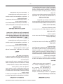
4. Remove delime port cap on top of unit and
insert funnel into delime port (Figure 4).
Figure 4
The steamer and its parts
are hot. Use care when operating, cleaning
or servicing the steamer. The cooking
compartment contains live steam and hot
water. Stay clear when opening the door.
WATER TREATMENT SYSTEM
A water treatment system is recommended for
the steamer. Refer to your supplier's manual
for normal maintenance procedures for proper
scale-free operation.
REMOVAL OF LIME SCALE
DEPOSITS
The steamer should be delimed when symptoms
occur (see Troubleshooting Chart). This is
in accordance with the minimum preventive
maintenance schedule required by the Warranty.
Read and follow the
instructions on the deliming material
package. Avoid contact with skin and eyes.
Wear plastic or rubber gloves and safety
goggles when handling. Wash thoroughly
after handling. If deliming solution comes
in contact with the skin or eyes, rinse
thoroughly with clean water.
The steamer and its parts
are hot. Use care when operating, cleaning
or servicing the steamer. The cooking
compartment contains live steam and hot
water. Stay clear when opening the door.
MAINTENANCE

— 15 —
C24EA SERIES ELECTRIC COUNTER CONVECTION STEAMERS
5. Pour deliming solution into the steam
generator slowly to avoid spillage.
6. Remove funnel from delime port then rinse
port with clean water.
7. Lightly coat delime port threads with Petrol-
Gel then install delime port cap. Cap must
be installed and tightened securely at all
times.
8. Turn power switch ON.
9. When ready light comes on, turn cooking
timer on for 3 minutes to delime the steam
tubes and nozzles.
10. After 40 minutes, turn power switch OFF and
allow steam generator to completely drain,
15 minutes.
11. Rinse steam generator with clean water:
A. Turn power switch ON. When ready light
comes on, turn cooking timer on for 3
minutes to rinse the steam tubes and
nozzles.
B. Turn power switch OFF and allow steam
generator to completely drain.
C. Turn cooking timer to OFF.
D. Repeat steam generator rinse one time.
12. Clean exterior and interior using a mild
solution of soap and water. Rinse with clean
water then dry with a soft cloth.
13. Leave compartment door open when not in
use.
14. The steamer is ready for operation or
shutdown.
DOOR GASKET
If the door gasket is leaking due to a nick or
cut, it must be replaced. Damage to the gasket
sealing surface will cause steam leakage.
DRAINING STEAM GENERATOR
Drain the steam generator at the end of each
day to fl ush out minerals and minimize scale
build-up. The generator drains automatically
for approximately 15 minutes after the power
switch is turned.

— 16 —
C24EA SERIES ELECTRIC COUNTER CONVECTION STEAMERS
COOKING HINTS
The steamer effi ciently cooks vegetables and
other foods for immediate serving. Steam
cooking should be carefully time controlled.
Keep hot food holding-time to a minimum to
produce the most appetizing results. Prepare
small batches. Cook only enough to start serving,
then cook additional amounts to meet demand.
PREPARATION
Prepare vegetables, fruits, meats, seafood and
poultry normally by cleaning, separating, cutting,
removing stems, etc. Cook root vegetables in
a perforated pan. Other vegetables may be
cooked in a perforated pan unless juices are
being saved. Liquids can be collected in a solid
12" x 20" pan placed under a perforated pan.
Perforated pans are used for frankfurters,
wieners and similar items when juices do not
need to be preserved. Solid pans are good
for cooking puddings, rice, and hot breakfast
cereals. Vegetables and fruits are cooked in
solid pans in their own juice. Meats and poultry
are cooked in solid pans to preserve their juice
or retain broth.
Canned foods can be heated in their opened
cans (cans placed in 12" x 20" solid pans) or
the contents may be poured into solid pans.
DO NOT place unopened cans in the steamer.
Frozen Food Items
Separate frozen foods into smaller pieces to
allow more effi cient cooking.
Use a pan cover for precooked frozen dishes
that cannot be cooked in the covered containers
in which they are packed if they require more
than 15 minutes of cooking time. When a cover is
used, approximately one-third additional cooking
time is necessary.
Cooking time for frozen foods depends on the
amount of defrosting required. If time permits,
allow frozen foods to partially thaw overnight in
a refrigerator. This will reduce their cooking time.
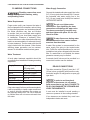
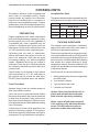
Acceptable Pan Sizes
The steamer accommodates combinations of full,
half and one-third size pans, solid or perforated.
Model Number of Pans Accommodated
Depth of Pan
1" 21/2"4" 6"
C24EA3 6321
C24EA5 10 5 3 2
COOKING GUIDELINES
The steamer cooks vegetables, frankfurters,
eggs in their shells, and certain other meats or
food items at atmospheric pressure.
These cooking guidelines are suggestions only.
You should experiment with your food products
to determine the cooking times that will give you
the best results. Variables which aff ect cooking
time include size, weight, thickness of foods,
temperature, density, previous condition of the
foods (fresh, pre-blanched or frozen) and degree
of doneness desired.
Cook times will vary and are aff ected by.
1. Starting temperature of frozen, refrigerated,
and fresh foods.
2. Your location's altitude.
3. Type and size of pan used.
4. Covered or uncovered.
Caution: Pans covered with lids, foil, or
plastic wrap will hold hot condensate
water that can spill during unloading.
Notice: Loose foil and plastic wrap left
in the cooking cavity will block the drain
screen. This will cause the cavity to
pressurize and the door seal to leak.

— 17 —
C24EA SERIES ELECTRIC COUNTER CONVECTION STEAMERS
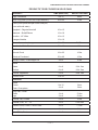
PRODUCT TIME (MINUTES) WEIGHT PER PAN
Eggs, Scrambled 9 to 12 8 doz.
Rice, Long Grain (Cover with 4 cups water/lb.) 23 to 25 2 lbs.
Pasta (Place perforated pan inside solid pan,
cover with cold water)
Spaghetti – Regular/Vermicelli 10 to 15
Macaroni - Shells/Elbows 13 to 18
Noodles - 1/2" Wide 10 to 15
Lasagna Noodles 13 to 18
Frozen Casseroles, Lasagna 33 to 35 Full Pan
Meat Loaf, 3-5 Lb. Each 38 to 40 15 lbs.
Beef
Ground Chuck 19 to 25 10 lbs.
Sliced as Purchased 33 to 40 10 lbs.
Shrimp, Frozen, 10 Shrimp per Lb. 4 to 5 4 lbs.
Beans
Baked 8 to 9 10 lb. Can
Refried 8 to 9 10 lb. Can
Canned Vegetables 5 to 6 10 lb. Can
Prunes, Dried 11 to 15
SEAFOOD
Clams
Frozen
Fresh, Cherrystone
9 to 12
4 to 6
3 doz.
3 doz.
King Crab, Frozen
Claws
Legs
3 to 4
3 to 6
21/2 lbs.
41/2 lbs.
Lobster Tail, Frozen 5 to 6 10 lbs.
Lobster, Live, 10" - 12" 4 to 5 4 Per Pan
Salmon Fillets, Frozen, 8 ounce each 4 to 5 71/2 lbs.
Scallops, Fresh 3 to 4 3 lbs.
Scrod Fillets, Fresh 3 to 5 4 lbs.
PRODUCTS TO BE COOKED IN SOLID PANS

— 18 —
C24EA SERIES ELECTRIC COUNTER CONVECTION STEAMERS
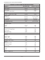
PRODUCTS TO BE COOKED IN PERFORATED PANS
PRODUCT TIME (MINUTES) WEIGHT PER PAN
EGGS
Hard Cooked 14 to 15 4 doz.
Soft Cooked 8 to 10 4 doz.
Soft Yoke for Caesar Salad 5 to 8 4 doz.
MEATS
Chicken — Breasts, Legs, Thighs 19 to 20 15 lbs.
Turkey, Frozen
Breasts (2) 86 to 90 6 to 7 lbs. Each
Cut Lengthwise 53 to 55 20 to 25 lbs.
Corned Beef 40 to 75 6 to 8 lbs.
Hot Dogs and Wieners 2 to 3 80 to 100 Count
VEGETABLES
Asparagus Spears
Frozen 10 to 12 3 lbs.
Fresh 4 to 5 5 lbs.
Beans
Green 2" Cut, Frozen/Fresh 5 to 6 5 lbs.
Lima, Frozen 7 to 8 5 lbs.
Baby Lima, Frozen 4 to 5 5 lbs.
Brussel Sprouts, Frozen 5 to 6 5 lbs.
Broccoli
Spears, Frozen 6 to 8 4 lbs.
Spears, Fresh 4 to 6 5 lbs.
Flowerettes, Frozen 4 to 6 5 lbs.
Cabbage, Fresh, 1/6 Cut 6 to 8 5 lbs.
Carrots
Baby Whole, Frozen 6 to 8 7 lbs.
Crinkle Cut, Frozen 7 to 8 4 lbs.
Sliced, Fresh 9 to 11 9 lbs.
Caulifl ower, Flowerettes
Frozen 4 to 6 4 lbs.
Fresh 7 to 8 5 lbs.
Celery, 1" Diagonal Cut 5 to 7 5 lbs.

— 19 —
C24EA SERIES ELECTRIC COUNTER CONVECTION STEAMERS
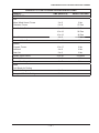
PRODUCTS TO BE COOKED IN PERFORATED PANS
PRODUCT TIME (MINUTES) WEIGHT PER PAN
VEGETABLES
Corn
Yellow Whole Kernel, Frozen 3 to 5 5 lbs.
Cobbettes, Frozen 6 to 8 27 Ears
Corn-On-Cob, Fresh 16 to 18 80 Ears
16 to 18 54 Ears
10 to 12 18 Ears
Peas, Green 4 to 6 5 lbs.
Potatoes, Whole Russet 50 to 55 40 lbs.
Spinach
Chopped, Frozen 15 to 17 6 lbs.
Defrosted 4 to 5 6 lbs.
Fresh Cut 2 to 3 2 lbs.
Squash, Acorn Halves 22 to 25 10 Halves
Zucchini, Slices 6 to 8 10 lbs.
Frozen Mixed Vegetables 6 to 7 5 lbs.
FRUIT
Fruit, Blanch for Peeling
Grapefruit, Oranges 2 to 3
Pineapple, Whole for Cutting 2 to 4

— 20 —
C24EA SERIES ELECTRIC COUNTER CONVECTION STEAMERS
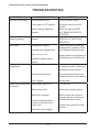
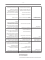
SYMPTOMS POSSIBLE CAUSES REMEDY
Steamer not steaming No main power source
Power switch in OFF position
Water not being supplied to
steamer
Check the power source.
Set power switch to the ON
position.
Refer to symptom WATER
NOT BEING SUPPLIED TO
STEAMER.
Steamer not heating/
steaming properly
Excessive lime build up in the
steamer
Descale the steamer (see
REMOVAL OF LIME SCALE
DEPOSITS).
Door leaks Damaged door gasket
Improper drain Plugged drain
High water pressure
Damage to gasket sealing
surface
Check door gasket for damage.
If adjustment is needed, contact
your Authorized Vulcan Servicer.
Water pressure must between 20
PSIG fl owing and 60 PSIG static.
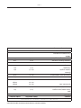
Water accumulates in
compartment
Plugged drain or screen
Unit not leveled properly
Drain clogged
Clear compartment cavity screen.
If symptom persists, contact your
Authorized Vulcan Servicer.
See leveling instructions in the
installation section of this manual.
Unclog drain.
Water not being supplied
to steamer
Water supply valve is off
Water pressure low
Water fi lter is plugged
Domestic washing machine
hoses with fl ow safe check
valves used.
Valve inlet screen clogged
Turn valve on.
Check water supply pressure.
Refer to water fi lter manual. If
symptom persists, contact your
Authorized Vulcan Servicer.
Contact your Authorized Vulcan
Servicer.
TROUBLESHOOTING
La page est en cours de chargement...
La page est en cours de chargement...
La page est en cours de chargement...
La page est en cours de chargement...
La page est en cours de chargement...
La page est en cours de chargement...
La page est en cours de chargement...
La page est en cours de chargement...
La page est en cours de chargement...
La page est en cours de chargement...
La page est en cours de chargement...
La page est en cours de chargement...
La page est en cours de chargement...
La page est en cours de chargement...
La page est en cours de chargement...
La page est en cours de chargement...
La page est en cours de chargement...
La page est en cours de chargement...
La page est en cours de chargement...
La page est en cours de chargement...
La page est en cours de chargement...
La page est en cours de chargement...
La page est en cours de chargement...
La page est en cours de chargement...
La page est en cours de chargement...
La page est en cours de chargement...
La page est en cours de chargement...
La page est en cours de chargement...
-
 1
1
-
 2
2
-
 3
3
-
 4
4
-
 5
5
-
 6
6
-
 7
7
-
 8
8
-
 9
9
-
 10
10
-
 11
11
-
 12
12
-
 13
13
-
 14
14
-
 15
15
-
 16
16
-
 17
17
-
 18
18
-
 19
19
-
 20
20
-
 21
21
-
 22
22
-
 23
23
-
 24
24
-
 25
25
-
 26
26
-
 27
27
-
 28
28
-
 29
29
-
 30
30
-
 31
31
-
 32
32
-
 33
33
-
 34
34
-
 35
35
-
 36
36
-
 37
37
-
 38
38
-
 39
39
-
 40
40
-
 41
41
-
 42
42
-
 43
43
-
 44
44
-
 45
45
-
 46
46
-
 47
47
-
 48
48


Vulcan-Hart ML-152031 Le manuel du propriétaire
- Taper
- Le manuel du propriétaire
dans d''autres langues
- English: Vulcan-Hart ML-152031 Owner's manual
Documents connexes
Autres documents
-
Vulcan C24GA10 PS Le manuel du propriétaire
-
Vulcan C24GA Steamer Le manuel du propriétaire
-
-
-
Blodgett COS-8E Mode d'emploi
-
Blodgett COS6 spécification
-
-
 Amerec AK Generator, "AK4.5", "AK6", "AK7.5", "AK9", "AK11" & "AK14" Mode d'emploi
-
Blodgett COS-8GDS Mode d'emploi
-
