Hitachi 50mry Manuel utilisateur
- Catégorie
- Outils électroportatifs
- Taper
- Manuel utilisateur
Ce manuel convient également à

Model
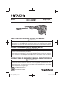
Rotary Hammer
Modèle
Marteau rotatif
Modelo
Martillo perforador
DH 40MEY
DOUBLE INSULATION
DOUBLE ISOLATION
AISLAMIENTO DOBLE
INSTRUCTIONS DE SECURITE ET MODE D’EMPLOI
AVERTISSEMENT
Une utilisation INCORRECTE OU DANGEREUSE de cet outil motorisé peut entraîner la
mort ou de sérieuses blessures corporelles!
Ce mode d’emploi contient d’importantes informations à propos de la sécurité de ce produit.
Prière de lire et de comprendre ce mode d’emploi AVANT d’utiliser l’outil motorisé. Garder ce
mode d’emploi à la disponibilité des autres utilisateurs et propriétaires avant qu’ils utilisent
l’outil motorisé. Ce mode d’emploi doit être conservé dans un endroit sûr.
SAFETY INSTRUCTIONS AND INSTRUCTION MANUAL
WARNING
IMPROPER OR UNSAFE use of this power tool can result in death or serious bodily injury!
This manual contains important information about product safety. Please read and
understand this manual BEFORE operating the power tool. Please keep this manual
available for other users and owners before they use the power tool. This manual should be
stored in safe place.
INSTRUCCIONES DE SEGURIDAD Y MANUAL DE INSTRUCCIONES
ADVERTENCIA
¡La utilización INAPROPIADA O PELIGROSA de esta herramienta eléctrica puede resultar
en lesiones de gravedad o la muerte!
Este manual contiene información importante sobre la seguridad del producto. Lea y com-
prenda este manual ANTES de utilizar la herramienta eléctrica. Guarde este manual para
que puedan leerlo otras personas antes de utilizar la herramienta eléctrica. Este manual
debe ser guardado en un lugar seguro.

CONTENTS
Page
IMPORTANT SAFETY INFORMATION .......................3
MEANINGS OF SIGNAL WORDS ...............................3
SAFETY ...........................................................................3
GENERAL POWER TOOL SAFETY WARNINGS ........3
SPECIFIC SAFETY RULES AND SYMBOLS ..............4
DOUBLE INSULATION FOR SAFER OPERATION .....5
FUNCTIONAL DESCRIPTION ........................................6
NAME OF PARTS ........................................................6
SPECIFICATIONS .......................................................7
Page
ASSEMBLY AND OPERATION .......................................7
APPLICATIONS ...........................................................7
PRIOR TO OPERATION ..............................................7
HOW TO USE ..............................................................9
USING DRILL CHUCK, CHUCK ADAPTOR ..............11
HOW TO USE THE CORE BIT ..................................11
MAINTENANCE AND INSPECTION ............................13
ACCESSORIES.............................................................14
STANDARD ACCESSORIES.....................................14
OPTIONAL ACCESSORIES ......................................14
English
TABLE DES MATIERES
Page
INFORMATIONS IMPORTANTES
DE SÉCURITÉ ......................................................16
SIGNIFICATION DES MOTS
D’AVERTISSEMENT .................................................16
SECURITE ....................................................................16
AVERTISSEMENTS DE SÉCURITÉ GÉNÉRAUX
CONCERNANT LES OUTILS ÉLECTRIQUES .....16
REGLES DE SECURITE SPECIFIQUES ET
SYMBOLES ..........................................................18
DOUBLE ISOLATION POUR UN
FONCTIONNEMENT PLUS SUR .........................19
DESCRIPTION FONCTIONNELLE ..............................20
NOM DES PARTIES ..................................................20
SPECIFICATIONS .....................................................20
Page
ASSEMBLAGE ET FONCTIONNEMENT .....................21
APPLICATIONS .........................................................21
AVANT L’UTILISATION ..............................................21
UTILISATION ............................................................. 23
UTILISATION DU MANDRIN PORTE-FORET
ET DU RACCORD DE MANDRIN .........................25
COMMENT UTILISER LA COURONNE ....................26
ENTRETIEN ET INSPECTION......................................27
ACCESSOIRES.............................................................28
ACCESSOIRES STANDARD.....................................28
ACCESSOIRES SUR OPTION ..................................28
Français
Página
INFORMACIÓN IMPORTANTE SOBRE
SEGURIDAD .........................................................30
SIGNIFICADO DE LAS PALABRAS DE
SEÑALIZACIÓN ....................................................30
SEGURIDAD .................................................................30
ADVERTENCIAS DE SEGURIDAD GENERAL
DE LA HERRAMIENTA ELÉCTRICA ....................30
NORMAS Y SÍMBOLOS ESPECÍFICOS DE
SEGURIDAD .........................................................32
AISLAMIENTO DOBLE PARA OFRECER UNA
OPERACIÓN MÁS SEGURA ................................33
DESCRIPCIÓN FUNCIONAL .......................................34
NOMENCLATURA ....................................................34
ESPECIFICACIONES ................................................ 34
Página
MONTAJE Y OPERACIÓN ............................................35
APLICACIONES ........................................................35
ANTES DE LA OPERACIÓN .....................................35
MODO DE UTILIZACIÓN ..........................................37
UTILIZACIÓN DEL PORTABARRENAS Y DEL
ADAPTADOR PARA PORTABARRENAS .............39
MODO DE USAR LA BARRENA TUBULAR..............40
MANTENIMIENTO E INSPECCIÓN .............................42
ACCESORIOS...............................................................43
ACCESORIOS ESTÁNDAR ......................................43
ACCESORIOS OPCIONALES ..................................43
Español
ÍNDICE

3
English
IMPORTANT SAFETY INFORMATION
Read and understand all of the safety precautions, warnings and operating instructions in the Instruction Manual before
operating or maintaining this power tool.
Most accidents that result from power tool operation and maintenance are caused by the failure to observe basic safety
rules or precautions. An accident can often be avoided by recognizing a potentially hazardous situation before it occurs,
and by observing appropriate safety procedures.
Basic safety precautions are outlined in the “SAFETY” section of this Instruction Manual and in the sections which contain
the operation and maintenance instructions.
Hazards that must be avoided to prevent bodily injury or machine damage are identifi ed by WARNINGS on the power tool
and in this Instruction Manual.
NEVER use this power tool in a manner that has not been specifi cally recommended by HITACHI.
MEANINGS OF SIGNAL WORDS
WARNING indicates a potentially hazardous situations which, if ignored, could result in death or serious injury.
CAUTION indicates a potentially hazardous situations which, if not avoided, may result in minor or moderate injury, or
may cause machine damage.
NOTE emphasizes essential information.
SAFETY
GENERAL POWER TOOL SAFETY WARNINGS
WARNING
Read all safety warnings and all instructions.
Failure to follow the warnings and instructions may result in electric shock, fi re and/or serious injury.
Save all warnings and instructions for future reference.
The term “power tool” in the warnings refers to your mains-operated (corded) power tool or battery-operated
(cordless) power tool.
1) Work area safety
a) Keep work area clean and well lit.
Cluttered or dark areas invite accidents.
b) Do not operate power tools in explosive
atmospheres, such as in the presence of
fl ammable liquids, gases or dust.
Power tools create sparks which may ignite the
dust or fumes.
c) Keep children and bystanders away while
operating a power tool.
Distractions can cause you to lose control.
2) Electrical safety
a) Power tool plugs must match the outlet.
Never modify the plug in any way.
Do not use any adapter plugs with earthed
(grounded) power tools.
Unmodified plugs and matching outlets will
reduce risk of electric shock.
b) Avoid body contact with earthed or grounded
surfaces such as pipes, radiators, ranges and
refrigerators.
There is an increased risk of electric shock if
your body is earthed or grounded.
c) Do not expose power tools to rain or wet
conditions.
Water entering a power tool will increase the
risk of electric shock.
d) Do not abuse the cord. Never use the cord for
carrying, pulling or unplugging the power tool.
Keep cord away from heat, oil, sharp edges
or moving parts.
Damaged or entangled cords increase the risk
of electric shock.
e) When operating a power tool outdoors, use
an extension cord suitable for outdoor use.
Use of a cord suitable for outdoor use reduces
the risk of electric shock.
f) If operating a power tool in a damp location
is unavoidable, use a residual current device
(RCD) protected supply.
Use of an RCD reduces the risk of electric shock.
3) Personal safety
a) Stay alert, watch what you are doing and use
common sense when operating a power tool.
Do not use a power tool while you are tired
or under the infl uence of drugs, alcohol or
medication.

4
English
A moment of inattention while operating power
tools may result in serious personal injury.
b) Use personal protective equipment. Always
wear eye protection.
Protective equipment such as dust mask,
non-skid safety shoes, hard hat, or hearing
protection used for appropriate conditions will
reduce personal injuries.
c) Prevent unintentional starting. Ensure the
switch is in the off -position before connecting
to power source and/or battery pack, picking
up or carrying the tool.
Carrying power tools with your finger on the
switch or energising power tools that have the
switch on invites accidents.
d) Remove any adjusting key or wrench before
turning the power tool on.
A wrench or a key left attached to a rotating part
of the power tool may result in personal injury.
e) Do not overreach. Keep proper footing and
balance at all times.
This enables better control of the power tool in
unexpected situations.
f) Dress properly. Do not wear loose clothing
or jewellery. Keep your hair, clothing and
gloves away from moving parts.
Loose clothes, jewellery or long hair can be
caught in moving parts.
g) If devices are provided for the connection
of dust extraction and collection facilities,
ensure these are connected and properly
used.
Use of dust collection can reduce dust-related
hazards.
4) Power tool use and care
a) Do not force the power tool. Use the correct
power tool for your application.
The correct power tool will do the job better and
safer at the rate for which it was designed.
b) Do not use the power tool if the switch does
not turn it on and off .
Any power tool that cannot be controlled with
the switch is dangerous and must be repaired.
c) Disconnect the plug from the power source
and/or the battery pack from the power tool
before making any adjustments, changing
accessories, or storing power tools.
Such preventive safety measures reduce the
risk of starting the power tool accidentally.
d) Store idle power tools out of the reach of
children and do not allow persons unfamiliar
with the power tool or these instructions to
operate the power tool.
Power tools are dangerous in the hands of
untrained users.
e) Maintain power tools. Check for misalignment
or binding of moving parts, breakage of parts
and any other condition that may aff ect the
power tool’s operation.
If damaged, have the power tool repaired
before use.
Many accidents are caused by poorly maintained
power tools.
f) Keep cutting tools sharp and clean.
Properly maintained cutting tools with sharp
cutting edges are less likely to bind and are
easier to control.
g) Use the power tool, accessories and tool bits
etc. in accordance with these instructions,
taking into account the working conditions
and the work to be performed.
Use of the power tool for operations different
from those intended could result in a hazardous
situation.
5) Service
a) Have your power tool serviced by a qualifi ed
repair person using only identical replacement
parts.
This will ensure that the safety of the power tool
is maintained.
SPECIFIC SAFETY RULES AND SYMBOLS
1. Wear ear protectors.
Exposure to noise can cause hearing
loss.
2. Use auxiliary handles, if supplied with the tool.
Loss of control can cause personal injury.
3. Hold power tools by insulated gripping surfaces
when performing an operation where the cutting
tool may contact hidden wiring or its own cord.
Cutting accessory contacting a “live” wire may make
exposed metal parts of the power tool “live” and could
give the operator an electric shock.
4. NEVER touch the tool bit with bare hands after
operation.
5. NEVER wear gloves made from materials likely to roll
up such as cotton, wool, cloth or string, etc.
6. ALWAYS attach the side handle and securely grip the
Rotary Hammer.
7. Never touch moving parts.
NEVER place your hands, fi ngers or other body parts
near the tool’s moving parts.
8. Never operate without all guards in place.
NEVER operate this tool without all guards or safety
features in place and in proper working order. If
maintenance or servicing requires the removal of a
guard or safety feature, be sure to replace the guard or
safety feature before resuming operation of the tool.

5
English
9. Use right tool.
Don’t force small tool or attachment to do the job of a
heavy-duty tool.
Don’t use tool for purpose not intended —for
example— don’t use circular saw for cutting tree limbs
or logs.
10. Never use a power tool for applications other than
those specifi ed.
NEVER use a power tool for applications other than
those specifi ed in the Instruction Manual.
11. Handle tool correctly.
Operate the tool according to the instructions provided
herein. Do not drop or throw the tool.
NEVER allow the tool to be operated by children,
individuals unfamiliar with its operation or unauthorized
personnel.
12. Keep all screws, bolts and covers tightly in place.
Keep all screws, bolts, and plates tightly mounted.
Check their condition periodically.
13. Do not use power tools if the plastic housing or
handle is cracked.
Cracks in the tool’s housing or handle can lead to
electric shock. Such tools should not be used until
repaired.
14. Blades and accessories must be securely
mounted to the tool.
Prevent potential injuries to youself or others. Blades,
cutting implements and accessories which have been
mounted to the tool should be secure and tight.
15. Keep motor air vent clean.
The tool’s motor air vent must be kept clean so that
air can freely fl ow at all times. Check for dust build-up
frequently.
16. Operate power tools at the rated voltage.
Operate the power tool at voltages specifi ed on its
nameplate.
If using the power tool at a higher voltage than the rated
voltage, it will result in abnormally fast motor revolution
and may damage the unit and the motor may burn out.
17. NEVER use a tool which is defective or operating
abnormally.
If the tool appears to be operating unusually, making
strange noises, or otherwise appears defective, stop
using it immediately and arrange for repairs by a
Hitachi authorized service center.
18. NEVER leave tool running unattended. Turn power
off .
Don’t leave tool until it comes to a complete stop.
19. Carefully handle power tools.
Should a power tool be dropped or struck against hard
materials inadvertently, it may be deformed, cracked,
or damaged.
20. Do not wipe plastic parts with solvent.
Solvents such as gasoline, thinner benzine, carbon
tetrachloride, and alcohol may damage and crack
plastic parts. Do not wipe them with such solvents.
Wipe plastic parts with a soft cloth lightly dampened
with soapy water and dry thoroughly.
21. ALWAYS wear eye protection that meets the
requirement of the latest revision of ANSI
Standard Z87.1.
22. ALWAYS be careful with buried object such as an
underground wiring.
Touching live wiring or electric cable with this tool may
result in electric shock.
Confi rm before use whether hidden objects are
present, such as electric cables within the wall, fl oor or
ceiling.
23. Defi nitions for symbols used on this tool
V....................volts
Hz .................hertz
A ...................amperes
n
o
..................no load speed
W ..................watt
..................Class II Construction
---/min ...........revolutions per minute
.................. Alternating current
DOUBLE INSULATION FOR SAFER
OPERATION
To ensure safer operation of this power tool, HITACHI has
adopted a double insulation design. “Double insulation”
means that two physically separated insulation systems
have been used to insulate the electrically conductive
materials connected to the power supply from the outer
frame handled by the operator. Therefore, either the
symbol
“
”
or the words “Double insulation” appear on
the power tool or on the nameplate.
Although this system has no external grounding, you must
still follow the normal electrical safety precautions given in
this Instruction Manual, including not using the power tool
in wet environments.
To keep the double insulation system eff ective, follow
these precautions:
○
Only HITACHI AUTHORIZED SERVICE CENTER
should disassemble or assemble this power tool, and
only genuine HITACHI replacement parts should be
installed.
○
Clean the exterior of the power tool only with a soft cloth
moistened with soapy water, and dry thoroughly.
Never use solvents, gasoline or thinners on plastic
components; otherwise the plastic may dissolve.

6
English
SAVE THESE INSTRUCTIONS
AND
MAKE THEM AVAILABLE TO OTHER USERS
AND
OWNERS OF THIS TOOL!
FUNCTIONAL DESCRIPTION
NOTE
The information contained in this Instruction Manual is designed to assist you in the safe operation and maintenance
of the power tool.
NEVER operate, or attempt any maintenance on the tool unless you have fi rst read and understood all safety instructions
contained in this manual.
Some illustrations in this Instruction Manual may show details or attachments that diff er from those on your own power
tool.
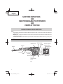
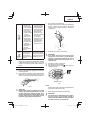
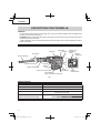
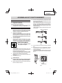
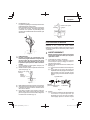
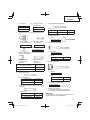
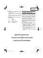
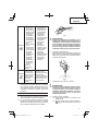
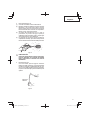
NAME OF PARTS
Fig. 1
Front cap
Housing
Stopper
Grip
Switch trigger
Side handle
Nameplate
Tail cover
Set screw
(Under the Tail
cover)
Selector lever
Drill bit
Rotation speed
selector switch
Power lamp
Display lamp
Handle

7
English
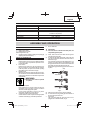
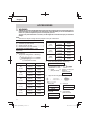
SPECIFICATIONS
Motor Brushless motor
Power Source Single-Phase, 120 V 60 Hz
Current 11.3 A
Capacity Drill Bit: 1-9/16" (40 mm)
Core Bit: 4-1/8" (105 mm)
No-Load Speed 250 – 460 /min
Full-load Blow 1,430 – 2,850 /min
Weight 16.5 lbs (7.5 kg)
ASSEMBLY AND OPERATION
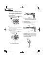
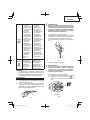
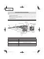
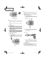
6. How to install tool
CAUTION
For tools such as a drill bit and a bull point, use
only Hitachi genuine parts.
(1) Clean, then smear the tool shank with the grease
provided in the green tube.
(2) To attach the tool (SDS max shank), insert it into the
hole until it contacts the innermost end of the hole as
illustrated in Fig. 2.
If you continue to turn the tool with slight pressure, you
can feel a spot where there is a hitch. At that spot, pull
the grip to the direction of an arrow mark and insert the
tool all the way until it hits the innermost end.
Releasing the grip reverts the grip and secures the tool
in place.
Fig. 2
Grip
Tool
Tool shank
(3) Pull the tool to make sure it is locked completely.
(4) To remove the tool, fully pull the grip in the direction of
the arrow and pull out the tool.
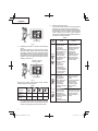
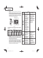
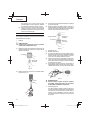
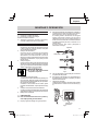
7. Power lamp
The power lamp lights up when the power cord is
plugged into an electrical outlet. (Fig. 3)
APPLICATIONS
Rotation and hammering function
○
Drilling anchor holes
○
Drilling holes in concrete
Hammering function only
○ Crushing concrete, chipping, digging, and squaring (by
applying optional accessories)
PRIOR TO OPERATION
1. Power source
Ensure that the power source to be utilized conforms
to the power source requirements specifi ed on the
product nameplate.
2. Power switch
Ensure that the switch is in the OFF position. If the
plug is connected to a receptacle while the switch is
in the ON position, the power tool will start operating
immediately and can cause serious injury.
3. Extension cord
When the work area is far away from the power source,
use an extension cord of suffi cient thickness and rated
capacity. The extension cord should be kept as short
as practicable.
WARNING
Damaged cord must be replaced
or repaired.
4. Check the receptacle
If the receptacle only loosely accepts the plug, the
receptacle must be repaired. Contact a licensed
electrician to make appropriate repairs.
If such a fautly receptacle is used, it may cause
overheating, resulting in a serious hazard.
5. Confi rming condition of the environment:
Confi rm that the work site is placed under appropriate
conditions conforming to prescribed precautions.

8
English
Fig. 3
Power lamp
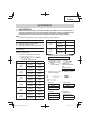
8. Regulating the number of rotations and hammering
(Fig. 4)
This Rotary Hammer is equipped with a built-in
electronic control circuit that can adjust and regulate
the number of rotations and times of hammering. This
Rotary Hammer can be used by adjusting the rotation
speed selector switch, depending upon the contents of
operation, such as boring holes into fragile materials,
chipping, centering, etc.
Fig. 4
Rotation speed
selector switch
Display lamp
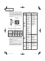
Pressing the rotation speed selector switch switches
rotation speeds as shown in Table 1.
Table 1
Display lamp
sequence
Full-load
speed
250 330 410 500
Impacts per
Minute
1,430 1,900 2,370 2,850
NOTE
The rotation speed cannot be changed by pressing
the rotation speed selector switch while the motor is
rotating. To change speeds, switch off the tool fi rst.
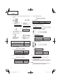
9. About the protection function
This tool has a built-in protection circuit for preventing
damage to the unit in the event of an abnormality.
Depending on the nature of the abnormality, the display
lamp will fl ash as shown in Table 2 and the unit will
cease to operate. In such cases, verify the problem
indicated by the fl ashing and take whatever steps are
necessary to correct the problem.
Table 2
Display
lamp
fl ashing
Cause Solution
Flash
or
RPM has gradually
decreased due
to the tool’s
temperature
increase protection
function detecting
temperatures
approaching the
unit’s specifi ed
temperature range
for automatic
shutdown.
(Power regulation
function)
* If one or two
bars of the
display lamp
are fl ashing, the
power regulation
function will not
be activated.
The tool will operate
normally once the
temperature has been
lowered by reducing
the workload.
Continued use
will activate the
temperature increase
protection function
which may result in
automatic shutdown.
(See box below)
Flash
The tool has
shut down
due to internal
temperatures
which exceed the
unit’s specifi ed
temperature.
(Temperature
increase protection
function)
Turn off the tool and
allow it to cool down
for about 15 to 30
minutes.
Once the temperature
is down, the unit
will recover when
the rotation speed
selector switch is
pressed.
Flash
The tool has
shut down due
to an overload
resulting from
the application of
excessive pressure
to the unit.
(Overload
protection function)
Press the rotation
speed selector switch
to recover. Try to avoid
tasks that will apply
excess pressure to
the unit.

9
English
Flash
1
Tool fails to
startup or has
shut down due
to the unit being
connected to a
power source
whose voltage
is either too high
or too low.
2
Tool has shut
down due to a
voltage signal
read error that
occurred from
the unit’s power
cord being
plugged in and
out at short
intervals.
(Circuit protection
function)
1
Connect the unit
to a power supply
matching the input
voltage specifi ed
on the nameplate.
Press the rotation
speed selector
switch to recover.
2
Allow for an interval
of 3 seconds
or more when
plugging the power
cord in and out.
Press the rotation
speed selector
switch to recover.
Flash
Tool fails to startup
or has shut down
due to a sensor
signal read error.
(Control monitoring
function)
Press the rotation
speed selector switch
to recover. Repair may
be required if this error
continuously occurs.
NOTE
Repair may be required if the display lamp continues
to fl ash after taking all necessary steps to correct the
problem. If the problem persists, please arrange for
repairs.
HOW TO USE
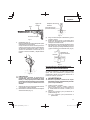
1. How to drill holes (Fig. 5)
(1) Pull the switch trigger after applying the drill bit tip to
the drilling position.
(2) It is unnecessary to forcibly press the Rotary Hammer
main body. It is suffi cient to slightly press the rotary
hammer to an extent that clips are freely discharged.
Fig. 5
CAUTION
Although this machine is equipped with a slip
clutch, if the drill bit becomes bound in concrete
or other material, the resultant stoppage of the
drill bit could cause the machine body to turn in
reaction. Ensure that the main handle and side
handle are gripped fi rmly during operation.
2. How to chisel or demolish (Fig. 6)
By applying the tool tip to the chiseling or demolishing
position, operate the rotary hammer by utilizing
its empty weight. Forcible pressing or thrusting is
unnecessary.
Fig. 6
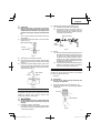
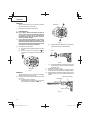
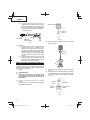
3. When drilling at “rotation + hammering”
CAUTION
If you switch the selector lever during motor
rotation, the tool can start to rotate abruptly,
resulting in unexpected accidents. Be sure to
switch the selector lever when the motor is at a
complete stop.
(1) Switching to “rotation + hammering”
(a) Turn the selector lever clockwise.
(b) Align ▲ of the selector lever and of the crank cover
as illustrated in Fig. 7.
Fig. 7
Selector lever
NOTE
Turn the selector lever to check if it is completely locked
and make sure that it does not turn.
4. When chipping and shredding at “hammering”:
CAUTION
○
If the selector lever is switched during motor rotation,
the tool can start to rotate abruptly, resulting in
unexpected accidents. Make sure to switch the selector
lever when the motor is at a complete stop.

10
English
○
If the bull point or cold chisel is used at the
position of “rotation + hammering”, the tool can
start to rotate, resulting in unexpected accidents.
Make sure that they are used at the positon of
“hammering”.
(1) Switching to “hammering”
(a) Turn the selector lever counterclockwise.
(b) Align ▲ of the selector lever and of the crank
cover as illustrated in Fig. 8.
Selector lever
Fig. 8
NOTE
Turn the selector lever to check if it is completely locked
and make sure that it does not turn.
(2) When fi xing working positions of tools such as cold
chisel, etc.,
(a) Turn the selector lever.
Align ▲ of the selector lever and
of the crank
cover as illustrated in Fig. 9.
Fig. 9
Selector lever
(b) Turn the Tool as illustrated in Fig. 10 and fi x the
tool to the desired working direction.
Fig. 10
Tool
(c) Switch the selector lever to “hammering”
according to the procedures mentioned in the
above item (1) and secure the position of the tool.
5. Install the stopper (Fig. 11)
(1) Loosen the wing bolt, and insert the stopper into the
mounting hole on the side handle.
(2) Adjust the stopper position according to the depth of
the hole and tighten the wing bolt securely.
Fig. 11
Stopper
Mounting hole
Wing bolt
6. Warming up (Fig. 12)
The grease lubrication system in this unit may require
warming up in cold regions.
Position the end of the bit so makes contact with the
concrete, turn on the switch and perform the warming
up operation. Make sure that a hitting sound is
produced and then use the unit.
Fig. 12

11
English
CAUTION
When the warming up operation is performed,
hold the side handle and the main body securely
with both hands to maintain a secure grip and be
careful not to twist your body by the jammed drill
bit.
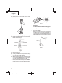
7. How to use the drill bit (taper shank) and the taper
shank adaptor.
(1) Install drill bit with taper shank in the taper shank
adaptor. (Fig. 13)
Fig. 13
Drill bit
(Taper shank)
Taper shank adaptor
(2) Turn the power on and drill a base hole.
(3) After cleaning out dust with a syringe, attach the plug
to the anchor tip and drive in the anchor with a manual
hammer.
(4) To remove the drill bit with taper shank, insert a cotter
into the slot of the taper shank adaptor, place supports
under the Rotary Hammer and tap the cotter with a
manual hammer. (Fig. 14)
Fig. 14
Taper shank
adaptor
Cotter
Support
USING DRILL CHUCK, CHUCK ADAPTOR
Note that this machine can be used at “rotation only”
if separately sold parts such as drill chuck and chuck
adaptor are attached. Use it with the selector lever
positioned at “rotation + hammering”.
WARNING
During operation, be sure to grip the handle and
the side handle fi rmly to prevent your body from
swaying.
(1) Switching to “rotation + hammering”
For switching to “rotation + hammering”, follow the same
procedures mentioned in [3. When drilling at “rotation
+ hammering”] in Page 9.
(2) Attaching chuck adaptor to drill chuck (Fig. 15)
(a) Attach the chuck adaptor to the drill chuck.
(b) The SDS max shank of the chuck adaptor is
equivalent to the drill bit. Therefore, follow the
same procedure as [6. How to install tool] in Page
7 for attaching and detaching.
Drill
chuck
Grip
Fig. 15
SDS max shank
Chuck
adaptor
(3) Drilling
(a) Even if you apply more-than-required pressure to
the machine body, drilling can never be performed
as quickly as you expect. Applying more force
or pressure to the machine body than what is
needed, on the contrary, damages the drill tip,
resulting in the declined working effi ciency and
shortened life of this machine.
(b) A drill can snap sometimes when drilling is almost
fi nished. It is important to relax your thrusting
pressure when drilling is nearing the end.
HOW TO USE THE CORE BIT
When boring penetrating large hole use the core bit. At
that time use with the center pin and the core bit shank
provided as optional accessories.
1. Mounting
CAUTION
Be sure to turn power OFF and disconnect the
plug from the receptacle.
(1) Mount the core bit to the core bit shank. (Fig. 16)
Lubricate the thread of the core bit shank to facilitate
disassembly.
Fig. 16
Core bit
Core bit shank

12
English
(2) Mount the core bit shank to the Rotary Hammer.
(Fig. 17)
Fig. 17
(3) Insert the center pin into the guide plate until it stops.
(4) Engage the guide plate with the core bit, and turn the
guide plate to left or right so that it does not fall even if
it faces downward. (Fig. 18)
Fig. 18
Center pin
Core bit
Core bit tip
Guide plate
2. How to bore (Fig. 19)
(1) Connect the plug to the receptacle.
(2) A spring is installed in the center pin. Push it lightly to
the wall or the fl oor straight. Connect all over the surface
of the core bit tip and start operating.
(3) When boring about 3/16" (5 mm) in depth the position
of the hole will establish. Bore after that removing the
center pin and the guide plate from core bit.
(4) Application of excessive force will not only expedite
the work, but will deteriorate the tip edge of the drill bit,
resulting in reduced service life of the rotary hammer.
Fig. 19
CAUTION
When removing the center pin and the guide plate,
turn OFF the switch and disconnect the plug from
the receptacle.
3. Dismounting (Fig. 20)
Remove the core bit shank from the rotary hammer
and strike the head of the core bit shank strongly two
or three times with a manual hammer holding the core
bit, then the thread becomes loose and the core bit can
be removed.
Fig. 20
Core bit
shank

13
English
MAINTENANCE AND INSPECTION
WARNING
Be sure to switch power OFF and disconnect the plug from the receptacle during maintenance and inspection.
MODIFICATIONS
Hitachi Power Tools are constantly being improved
and modifi ed to incorporate the latest technological
advancements.
Accordingly, some parts may be changed without prior
notice.
1. Inspecting the drill bits
Since use of a dull tool will cause motor malfunctioning
and degraded effi ciency, replace the drill bit with a new
one or resharpening without delay when abrasion is
noted.
2. Inspecting the screws
Regularly inspect all screws and ensure that they are
properly tightened. Should any of the screws be loose,
retighten them immediately.
WARNING
Using this Rotary Hammer with loosen screws is
extremely dangerous.
3. Maintenance of the motor
The motor unit is the very “heart” of the power tool.
Exercise due care to ensure the motor does not
become damaged and/or wet with oil or water.
4. Grease replacement
This Rotary Hammer is of full air-tight construction to
protect against dust and to prevent lubricant leakage.
Therefore, this Rotary Hammer can be used without
lubrication for long periods. Replace the grease as
described below.
○
Grease Replacement Period
After purchase, replace grease after every 6 months
of usage. Ask for grease replacement at the nearest
authorized Service Center.
5. Service and repairs
All quality power tools will eventually require servicing or
replacement of parts because of wear from normal use.
To assure that only authorized replacement parts will
be used, all service and repairs must be performed by
a HITACHI AUTHORIZED SERVICE CENTER, ONLY.
6. Service parts list
CAUTION
●
Repair, modifi cation and inspection of Hitachi
Power Tools must be carried out by a Hitachi
Authorized Service Center.
This Parts List will be helpful if presented with the
tool to the Hitachi Authorized Service Center when
requesting repair or other maintenance.
In the operation and maintenance of power tools,
the safety regulations and standards prescribed
in each country must be observed.

14
English
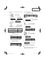
STANDARD ACCESSORIES
(1) Case (Molded plastic) (Code No. 337594) ...............1
(2) Side Handle (Code No. 330209)...............................1
(3) Stopper (Code No. 971786) .....................................1
(4) Hammer Grease A (Code No. 981840) ....................1
OPTIONAL ACCESSORIES.....sold
separately
For accessories in detail please call HITACHI AT
1-800-59-TOOLS
1. Through-hole drilling (Rotation + Hammering)
(1) Drill bit (SDS-max shank)
External dia. Overall length Code No.
5/8"
(16 mm)
13-3/8"
(340 mm)
313448
21-1/4"
(540 mm)
313456
3/4"
(19 mm)
13-3/8"
(340 mm)
313449
21-1/4"
(540 mm)
313457
7/8"
(22 mm)
12-5/8"
(320 mm)
313450
20-15/32"
(520 mm)
313458
1"
(25 mm)
12-5/8”
(320 mm)
313451
20-15/32"
(520 mm)
313459
1-1/8"
(28 mm)
14-9/16"
(370 mm)
313452
22-7/16"
(570 mm)
313460
External dia. Overall length Code No.
1-1/4”
(32 mm)
14-9/16"
(370 mm)
313453
22-7/16"
(570 mm)
313461
1-1/2”
(38 mm)
14-9/16"
(370 mm)
313454
22-7/16"
(570 mm)
313462
1-9/16”
(40 mm)
14-9/16"
(370 mm)
313455
22-7/16"
(570 mm)
313463
2. Anchor hole drilling (Rotation + Hammering)
(1) Drill Bit
(SDS-plus shank)
(2) Adaptor for SDS-plus
shank bit
(SDS max shank)
Code No. 313465
Adaptor for SDS-plus shank bit
+
3. Large-dia. hole boring (Rotation + Hammering)
(Guide plate) (1) Center pin
Code No. Code No.
985388 955165
955169
(2) Core bit (3) Core bit shank
(SDS max shank)
External dia.
2" (50 mm) Code No.
4-1/8" (105 mm) 313467
ACCESSORIES
WARNING
ALWAYS use Only authorized HITACHI replacement parts and accessories. Never use replacement parts or
accessories which are not intended for use with this tool. Contact HITACHI if you are not sure whether it is
safe to use a particular replacement part or accessory with your tool.
The use of any other attachment or accessory can be dangerous and could cause injury or mechanical
damage.
NOTE
Accessories are subject to change without any obligation on the part of the HITACHI.

15
English
4. Drilling holes....For drilling metals and wooden
materials
(1) 13mm drill chuck
(13VLD-D)
Code No. 321813
(2) Chuck adaptor
(SDS max shank)
Code No. 313468
(3) Chuck wrench
Code No. 930515
+
5. Bolt plaching operation with Chemical Anchor (Rotation
+ Hammering)
(1) Chemical Anchor Adaptor
(SDS max shank)
(Standard socket
on the market)
+
Square dimensions of the side
of the socket installation
Code No.
1/2" (12.7 mm) 313469
3/4" (19.0 mm) 313470
6. Crushing (Hammering)
(1) Bull point
Overall length Code No.
11" (280 mm) 313471
15-3/4" (400 mm) 313472
7. Groove digging and edging (Hammering)
(1) Cold chisel
Overall length Code No.
11" (280 mm) 313473
15-3/4" (400 mm) 313474
8. Asphalt cutting (Hammering)
(1) Cutter
Overall length Width Code No.
15-3/4" (400 mm) 1-31/32" (50 mm) 313475
9. Digging
(1) Scoop
Code No. 313476
10. Surface Roughing (Hammering)
(1) Bushing Tool
Code No. 313477
+
(2) Shank
Overall length Code No.
8-21/32" (220 mm) 313479
11. Tamping (Hammering)
(1) Rammer
Code No. 313478
+
(2) Shank
Overall length Code No.
8-21/32" (220 mm) 313479
12. Syringe (for chip removal)
Code No. 320859
13. Hammer grease A
1.1 lbs (500 g) (in a can) Code No. 335781
0.13 lbs (60 g) (in a tube) Code No. 335782
NOTE
Specifications are subject to change without any
obligation on the part of the HITACHI.

16
Français
INFORMATIONS IMPORTANTES DE SÉCURITÉ
Lire et comprendre toutes les précautions de sécurité, les avertissements et les instructions de fonctionnement dans ce
mode d’emploi avant d’utiliser ou d’entretenir cet outil motorisé.
La plupart des accidents causés lors de l’utilisation ou de l’entretien de l’outil motorisé proviennent d’un non respect des
règles ou précautions de base de sécurité. Un accident peut la plupart du temps être évité si l’on reconnaît une situation
de danger potentiel avant qu’elle ne se produise, et en observant les procédures de sécurité appropriées.
Les précautions de base de sécurité sont mises en évidence dans la section “SECURITE” de ce mode d’emploi et dans
les sections qui contiennent les instructions de fonctionnement et d’entretien.
Les dangers qui doivent être évités pour prévenir des blessures corporelles ou un endommagement de la machine sont
identifi és par AVERTISSEMENTS sur l’outil motorisé et dans ce mode d’emploi.
NE JAMAIS utiliser cet outil motorisé d’une manière qui n’est pas spécifi quement recommandée par HITACHI.
SIGNIFICATION DES MOTS D’AVERTISSEMENT
AVERTISSEMENT indique des situations potentiellement dangereuses qui, si elles sont ignorées, pourraient entraîner
la mort ou de sérieuses blessures.
PRECAUTION indique des situations dangereuses potentilles qui, si elles ne sont pas évitées, peuvent entraîner de
mineures et légères blessures ou endommager la machine.
REMARQUE met en relief des informations essentielles.
SECURITE
AVERTISSEMENTS DE SÉCURITÉ GÉNÉRAUX CONCERNANT LES OUTILS ÉLECTRIQUES
AVERTISSEMENT
Lire tous les avertissements de sécurité et toutes les instructions
Tout manquement à observer ces avertissements et instructions peut engendrer des chocs électriques, des incendies
et/ou des blessures graves.
Conservez tous les avertissements et toutes les instructions pour vous y référer ultérieurement.
Le terme "outil électrique", utilisé dans les avertissements, se réfère aux outils électriques (câblé) ou aux outils à piles
(sans fi l).
1) Sécurité de l’aire de travail
a) Maintenir l’aire de travail propre et bien
éclairée.
Les endroits encombrés ou sombres sont
propices aux accidents.
b) Ne pas utiliser d’outils électriques en
présence de liquides, gaz ou poussière
infl ammables, au risque de provoquer une
explosion.
Les outils électriques créent des étincelles
susceptibles d’enfl ammer la poussière.
c) Ne pas laisser les enfants et les visiteurs
s’approcher de vous lorsque vous utiliser
un outil électrique.
Les distractions peuvent faire perdre le contrôle.
2) Sécurité électrique
a) Les prises de l’outil électrique doivent
correspondre à la prise secteur.
Ne jamais modifi er la prise.
Ne pas utiliser d’adaptateurs avec les outils
électriques mis à la masse.
Les prises non modifi ées et les prises secteurs
correspondantes réduisent les risques de choc
électrique.
b) Eviter tout contact avec les surfaces mises
à la masse telles que les tuyaux, radiateurs,
bandes et réfrigérateurs.
Le risque de choc électrique est accru en cas de
mise à la masse du corps.
c) Ne pas exposer les outils électriques à la
pluie ou à des conditions humides.
Si l’eau pénètre dans l’outil, cela augmente les
risques de choc électrique.
d) Ne pas utiliser le cordon à tort. Ne jamais
utiliser le cordon pour transporter ou
débrancher l’outil électrique.
Maintenir le cordon loin de la chaleur, de
l’huile, des bords pointus ou des pièces
mobiles.
Les cordons endommagés ou usés augmentent
les risques de choc électrique.

17
Français
e) En cas d’utilisation d’un outil électrique à
l’extérieur, utiliser un cordon de rallonge
adapté à un usage extérieur.
L’utilisation d’un cordon adapté à l’usage extérieur
réduit les risques de choc électrique.
f) Si vous devez utiliser un outil électrique dans
un endroit humide, utilisez une alimentation
protégée contre les courants résiduels.
L’utilisation d’un dispositif de protection contre
les courants résiduels réduit le risque de choc
électrique.
3) Sécurité personnelle
a) Restez alerte, regarder ce que vous faites et
usez de votre bon sens en utilisant un outil
électrique.
Ne pas utiliser d’outil électrique si vous êtes
sous l’infl uence de drogues, d’alcool ou de
médicaments.
Pendant l’utilisation d’outils électrique, un instant
d’inattention peut entraîner des blessures graves.
b) Utiliser un équipement de protection
individuelle. Toujours porter des verres de
protection.
L’utilisation d’équipements de protection tels
que les masques anti-poussière, les chaussures
de sécurité anti-dérapantes, les casques ou
les protections auditives dans des conditions
appropriées réduisent les risques de blessures.
c) Empêcher les démarrages intempestifs.
Veiller à ce que l’interrupteur soit en
position d’arrêt avant de brancher à une
source d’alimentation et/ou une batterie, de
ramasser l’outil au sol ou de le transporter.
Transporter les outils électriques avec le doigt sur
l’interrupteur ou brancher les outils électriques
avec l’interrupteur en position de marche peut
entraîner des accidents.
d) Retirer toute clé de sécurité ou clé avant de
mettre l’outil électrique en marche.
Laisser une clé ou une clé de sécurité sur une
partie mobile de l’outil électrique peut engendrer
des blessures.
e) Ne pas trop se pencher. Toujours garder une
bonne assise et un bon équilibre pendant le
travail.
Cela permet un meilleur contrôle de l’outil
électrique dans des situations imprévisibles.
f) Porter des vêtements adéquats. Ne pas porter
de vêtements amples ni de bijoux. Maintenir
les cheveux, les vêtements et les gants loin
des pièces mobiles.
Les vêtements amples ou les cheveux longs
peuvent se prendre dans les pièces mobiles.
g) En cas de dispositifs destinés au
raccordement d’installations d’extraction et
de recueil de la poussière, veiller à ce qu’ils
soient correctement raccordés et utilisés.
L’utilisation d’un dispositif de collecte de la
poussière peut réduire les dangers associés à
la poussière.
4) Utilisation et entretien d’un outil électrique
a) Ne pas forcer sur l’outil électrique. Utiliser
l’outil électrique adapté à vos travaux.
Le bon outil électrique fera le travail mieux et en
toute sécurité au régime pour lequel il a été conçu.
b) Ne pas utiliser l’outil électrique si
l’interrupteur ne le met pas en position de
marche et d’arrêt.
Tout outil ne pouvant être contrôlé par l’interrupteur
est dangereux et doit être réparé.
c) Débrancher la prise ou retirer la batterie avant
de procéder à des réglages, au remplacement
des accessoires ou au stockage des outils
électriques.
Ces mesures préventives de sécurité réduisent
les risques de démarrage accidentel de l’outil
électrique.
d) Stockez les outils électriques inutilisés hors
de la portée des enfants et ne pas laisser des
personnes non familiarisées avec l’outil ou
ces instructions utiliser l’outil électrique.
Les outils électriques sont dangereux entre les
mains d’utilisateurs non habilités.
e) Entretenir les outils électriques. Vérifier
l’absence de mauvais alignement ou d’arrêt,
d’endommagement de pièces ou toute autre
condition susceptible d’aff ecter l’opération
de l’outil.
Si l’outil est endommagé, le faire réparer
avant utilisation.
De nombreux accidents sont dus à des outils mal
entretenus.
f) Maintenir les outils coupants aiguisés et
propres.
Des outils coupants bien entretenus avec des
bords aiguisés sont moins susceptibles de se
coincer et plus simples à contrôler.
g) Utiliser l’outil électrique, les accessoires
et les mèches de l’outil, etc. conformément
à ces instructions en tenant compte des
conditions d’utilisation et du travail à réaliser.
L’utilisation de l’outil électrique pour des
opérations diff érentes de celles pour lesquelles
il a été conçu est dangereuse.
5) Service
a) Faire entretenir l’outil électrique par un
technicien habilité à l’aide de pièces de
rechange identiques exclusivement.
Cela garantira le maintien de la sécurité de
l’outil électrique. lesquelles il a été conçu est
dangereuse.

18
Français
REGLES DE SECURITE SPECIFIQUES ET
SYMBOLES
1. Porter des protections anti-bruit.
L’exposition au bruit peut engendrer une
perte de l’audition.
2. Utilisez les poignées auxiliaires, si fourni avec
l’outil.
Toute perte de contrôle peut entraîner des blessures.
3. Tenir les outils électriques par les surfaces de
grippage lors de la réalisation d’opération où
l’outil de coupe risque d’entrer en contact avec
des câbles cachés ou son propre cordon.
Le contact d’un outil de coupe avec un fi l “sous tension”
risque de mettre les parties métalliques de l’outil “sous
tension” d’électrocuter l’utilisateur.
4. NE JAMAIS toucher la mèche avec des mains nues
après l’utilisation.
5. NE JAMAIS porter de gants faits d’une matière qui
risque de s’enrouler, comme du coton, de la laine, de la
toile ou de la fi celle, etc.
6. TOUJOURS fi xer la poignée latérale et tenir le marteau
rotatif solidement.
7. NE JAMAIS toucher les parties mobiles.
NE JAMAIS placer ses mains, ses doigts ou toute autre
partie de son corps près des parties mobiles de l’outil.
8. NE JAMAIS utiliser l’outil sans que tous les
dispositifs de sécurité ne soient en place.
NE JAMAIS faire fonctionner cet outil sans que tous
les dispositifs et caractéristiques de sécurité ne soient
en place et en état de fonctionnement. Si un entretien
ou une réparation nécessite le retrait d’un dispositif ou
d’une caractéristique de sécurité, s’assurer de bien
remettre en place le dispositif ou la caractéristique de
sécurité avant de recommencer à utiliser l’outil.
9. Utiliser l’outil correct
Ne pas forcer sur un petit outil ou accessoire pour faire
le travail d’un outil de grande puissance. Ne pas utiliser
un outil pour un usage pour lequel il n’a pas été prévu:
par exemple, ne pas utiliser une scie circulaire pour
couper des branches d’arbre ou des bûches.
10. NE JAMAIS utiliser un outil motorisé pour des
applications autres que celles spécifi ées.
NE JAMAIS utiliser un outil motorisé pour des
applications autres que celles spécifi ées dans le mode
d’emploi.
11. Manipuler l’outil correctement
Utiliser l’outil de la façon indiquée dans ce mode
d’emploi. Ne pas laisser tomber ou lancer l’outil. NE
JAMAIS permettre que l’outil soit utilisé par des
enfants, des personnes non familiarisées avec son
fonctionnement ou un personnel non autorisé.
12. Maintenir toutes les vis, tous les boulons et les
couvercles fermement en place.
Maintenir toutes les vis, tous les boulons et les
couvercles fermement montés. Vérifi er leurs
conditions périodiquement.
13. Ne pas utiliser les outils motorisés si le
revêtement de plastique ou la poignée est fendu.
Des fentes dans le revêtement ou la poignée peuvent
entraîner une électrocution. De tels outils ne doivent
pas être utilisés avant d’être réparé.
14. Les lames et les accessoires doivent être
fermement montés sur l’outil.
Eviter les blessures potentielles personnelles et aux
autres. Les lames, les instruments de coupe et les
accessoires qui ont été montés sur l’outil doivent être
fi xés et serrés fermement.
15. Garder propres les évents d’air du moteur.
Les évents d’air du moteur doivent être maintenus
propres de façon que l’air puisse circuler librement
tout le temps. Vérifi er les accumulations de poussière
fréquemment.
16. Utiliser l’outil motorisé à la tension nominale.
Utiliser l’outil motorisé à la tension spécifi ée sur sa
plaque signalétique.
Si l’on utilise l’outil motorisé avec une tension
supérieure à la tension nominale, il en résultera une
rotation anormalement trop rapide du moteur et cela
risque d’endommager l’outil et le moteur risque de
griller.
17. NE JAMAIS utiliser un outil défectueux ou qui
fonctionne anormalement.
Si l’outil n’a pas l’air de fonctionner normalement, fait
des bruits étranges ou sans cela paraît défectueux,
arrêter de l’utiliser immédiatement et le faire réparer
par un centre de service Hitachi autorisé.
18. NE JAMAIS laisser fonctionner l’outil sans
surveillance. Le mettre hors tension.
Ne pas abandonner l’outil avant qu’il ne soit
complètement arrêté.
19. Manipuler l’outil motorisé avec précaution.
Si un outil motorisé tombe ou frappe un matériau dur
accidentellement, il risque d’être déformé, fendu ou
endommagé.
20. Ne pas essuyer les parties en plastique avec du
solvant.
Les solvants comme l’essence, les diluants, la
benzine, le tétrachlorure de carbone et l’alcool peuvent
endommager et fi ssurer les parties en plastique. Ne
pas les essuyer avec de tels solvants.
Essuyer les parties en plastique avec un chiff on doux
légèrement imbibé d’une solution d’eau savonneuse et
sécher minutieusement.
21. TOUJOURS porter des lunettes de protection qui
respectent les dernières révisions du
Standard ANSI Z87.1.

19
Français
22. TOUJOURS vérifi er s’il y a des objets encastrés, par
exemple des fi ls électriques. Le fait de toucher avec
l’outil un fi l ou un câble électrique sous tension risque
de provoquer une décharge électrique.
Avant l’utilisation, vérifi er s’il y a des objets dissimulés,
par exemple des câbles électriques, dans le mur, le
plancher ou le plafond.
23. Défi nitions pour les symboles utilisés sur cet outil
V .................volts
Hz ...............hertz
A .................ampères
n
o
...............vitesse sans charge
W ................watt
...............Construction de classe II
---/min .........tours par minute
...............Courant alternatif
DOUBLE ISOLATION POUR UN
FONCTIONNEMENT PLUS SUR
Pour assurer un fonctionnement plus sûr de cet outil
motorisé, HITACHI a adopté une conception à double
insolation. “Double isolation” signifi e que deux systèmes
d’isolation physiquement séparés ont été utilisés pour
isoler les matériaux conducteurs d’électricité connectés
à l’outil motorisé à partir du cadre extérieur manipulé par
l’utilisateur. C’est pourquoi, le symbole “ ” ou les mots
“Double insulation” (double isolation) apparaissent sur
l’outil motorisé ou sur la plaque signalétique.
Bien que ce système n’ait pas de mise à terre extérieure,
il est quand même nécessaire de suivre les précautions
de sécurité électrique données dans ce mode d’emploi,
y-compris de ne pas utiliser l’outil motorisé dans un
environnement humide.
Pour garder le système de double isolation eff ectif, suivre
ces précautions:
○
Seuls les CENTRES DE SERVICE AUTORISES
HITACHI peuvent démonter et remonter cet outil
motorisé et uniquement des pièces de rechange
HITACHI garanties d’origine doivent être utilisées.
○
Nettoyer l’extérieur de l’outil motorisé uniquement
avec un chiff on doux légèrement imbibé d’une solution
savonneuse et essuyer minutieusement.
Ne jamais utiliser des solvants, de l’essence ou des
diluants sur les parties en plastique; sinon le plastique
risquerait de se dissoudre.
CONSERVER CES INSTRUCTIONS
ET
LES METTRE A LA DISPOSITION DES AUTRES UTILISATEURS
ET
PROPRIETAIRES DE CET OUTIL!

20
Français
DESCRIPTION FONCTIONNELLE
REMARQUE
Les informations contenues dans ce mode d’emploi sont conçues pour assister l’utilisateur dans une utilisation sans
danger et un entretien de l’outil motorisé.
NE JAMAIS utiliser ni entreprendre une révision de l’outil sans avoir d’abord lu et compris toutes les instructions de
sécurité contenues dans ce manuel.
Certaines illustrations dans ce mode d’emploi peuvent montrer des détails ou des accessoires diff érents de ceux de
l’outil motorisé utilisé.
NOM DES PARTIES
Fig. 1
Capuchon avant
Carter
Quenouille
Attache coulissante
Interrupteur
Poignée
latérale
Poignée
Plaque
signalétique
Couvercle de queue
Vis de fi xation
(Sous le couvercle de queue)
Sélecteur
Foret de perçage
Sélecteur de
vitesse de
rotation
Témoin
d’affi chage
Témoin
d’alimentation
SPECIFICATIONS
Moteur Moteur sans balais
Source d’alimentation Secteur, 120 V 60 Hz, monophasé
Courant 11.3 A
Capacité Mèche: 1-9/16" (40 mm)
Couronne: 4-1/8" (105 mm)
Vitesse sans charge 250 – 460 /min.
Vitesse de percussion à pleine charge 1,430 – 2,850 /min.
Poids 16.5 lbs (7.5 kg)
La page est en cours de chargement...
La page est en cours de chargement...
La page est en cours de chargement...
La page est en cours de chargement...
La page est en cours de chargement...
La page est en cours de chargement...
La page est en cours de chargement...
La page est en cours de chargement...
La page est en cours de chargement...
La page est en cours de chargement...
La page est en cours de chargement...
La page est en cours de chargement...
La page est en cours de chargement...
La page est en cours de chargement...
La page est en cours de chargement...
La page est en cours de chargement...
La page est en cours de chargement...
La page est en cours de chargement...
La page est en cours de chargement...
La page est en cours de chargement...
La page est en cours de chargement...
La page est en cours de chargement...
La page est en cours de chargement...
La page est en cours de chargement...
La page est en cours de chargement...
La page est en cours de chargement...
La page est en cours de chargement...
La page est en cours de chargement...
-
 1
1
-
 2
2
-
 3
3
-
 4
4
-
 5
5
-
 6
6
-
 7
7
-
 8
8
-
 9
9
-
 10
10
-
 11
11
-
 12
12
-
 13
13
-
 14
14
-
 15
15
-
 16
16
-
 17
17
-
 18
18
-
 19
19
-
 20
20
-
 21
21
-
 22
22
-
 23
23
-
 24
24
-
 25
25
-
 26
26
-
 27
27
-
 28
28
-
 29
29
-
 30
30
-
 31
31
-
 32
32
-
 33
33
-
 34
34
-
 35
35
-
 36
36
-
 37
37
-
 38
38
-
 39
39
-
 40
40
-
 41
41
-
 42
42
-
 43
43
-
 44
44
-
 45
45
-
 46
46
-
 47
47
-
 48
48


Hitachi 50mry Manuel utilisateur
- Catégorie
- Outils électroportatifs
- Taper
- Manuel utilisateur
- Ce manuel convient également à
dans d''autres langues
- English: Hitachi 50mry User manual
- español: Hitachi 50mry Manual de usuario
Documents connexes
-
Hitachi DH 52MEY Safety Instructions And Instruction Manual
-
-
-
-
-
-
-
-
-