
INSTALLATION INSTRUCTIONS
GUIDE D’INSTALLATION
Read all instructions carefully before proceeding.
SAVE THIS GUIDE FOR FUTURE REFERENCE.
Lire toutes les instructions attentivement avant de
commencer l’installation.
CONSERVER POUR UN USAGE ULTÉRIEUR.
Serial numbers • Numéros de série
IMPORTANT • Record the serial numbers
IMPORTANT • Noter les numéros de série
PIVOT DOOR 3636
PORTE PIVOT 3636
2C
Door in alcove
Porte en alcôve
Page 7
Door close on wall
Fermeture sur le mur
Page 16
Door close on return panel
Fermeture sur le panneau de retour
Page 24
Door in wallmount
Porte murale
Page 32

Close on wall 2.2
Page 16
Close on return panel 2.3
Page 24
CORNER DOOR
2.1
Page 7
2.1
Configuration
ALCOVE DOOR CORNER DOOR
1.2B + 2.2
1.2B + 2.3
WALL MOUNT DOOR
2.1
2.1 + 3A
2 x 2.1
2.1 + 3B
1.1A + 2.2 + 3A
1.2A + 2.2 + 3B
1.2A + 2.3 + 3A
1.2A + 2.3 + 3B
1.2B + 1,2B + 2.4
2.4
Page 32
NOTE: ASSEMBLE THE IN THE FOLLOWING ORDER
NOTE: ASSEMBLER LES UNITÉS DANS L'ORDRE SUIVANT

NOTE: ASSEMBLE THE IN THE FOLLOWING ORDER
NOTE: ASSEMBLER LES UNITÉS DANS L'ORDRE SUIVANT
1A DEMI-MUR
1B PANNEAU DE RETOUR
2 PORTES
3A FENÊTRE ORDINAIRE
3B FENÊTRE SPÉCIALE
4A COMBO LINEAIRE ET COMPACTE
4B COMBO ANGULAIRE
2
Installation guides sequence:
Séquence de guides d'installation:
1A HALF WALL
1B RETURN PANEL
2 DOORS
3A REGULAR WINDOW
3B SPECIAL WINDOW
4A LINEAR AND COMPACT COMBO
4B ANGULAR COMBO
3
A FENÊTRE ORDINAIR
E
3
B FENÊTRE SPÉCIAL
E
4
A COMBO LINEAIRE ET COMPACT
E
4
B COMBO ANGULAIR
E
3
A REGULAR WINDO
W
3
B SPECIAL WINDO
W
4
A
L
INEAR AND COMPACT COMBO
4
B
A
N
GU
LAR
CO
MB
O
1
A
D
EMI-MUR
1
B
P
ANNEAU DE RETOUR
1
A HALF WALL
1
B RETURN PANEL
Table of contents: Page
Tools and supplies.............................................................................................................. 4
Parts and components........................................................................................................ 5
2.1. Door in alcove installation............................................................................................ 7
2.2. Door closing on wall....................................................................................................16
2.3. Door closing on return panel.......................................................................................24
2.4. Door on wallmount installation....................................................................................32
Warranty.............................................................................................................................36
1A/1B + 2 + 3A/3B
1
A
/1
B
(Pivot door installation guide)
(Guide d'installation de porte pivot)
Already installed (if ordered)
Déjà installé (si commandé)
You are here
vous êtes ici
Table des matières: Page
Outils et matériaux.............................................................................................................. 4
Pièces et composantes....................................................................................................... 5
2.1. Installation de porte en alcôve..................................................................................... 7
2.2. Porte fermeture sur le mur..........................................................................................16
2.3. Porte fermeture sur le panneau de retour...................................................................24
2.4. Installation murale de porte.........................................................................................32
Garantie..............................................................................................................................36

Screwdriver
Tournevis
TOOLS
REQUIRED
OUTILS
REQUIS
Electric drill
Perçeuse électrique
24" level min.
Niveau de 24po. min.
Pencil
Crayon
Clear silicone sealant
Silicone claire
Measuring tape
Ruban à mesurer
18" square min.
Équerre de 18po. min.
Utility knife
Couteau à lame
rétractable
Safety equipment
Équipement de
sécurité
1/8" drill bits
Mèches de 1/8
SUPPLIES
SOLD SEPARATELY
MATÉRIAUX
VENDUS SÉPARÉMENT
Hacksaw
Scie à métaux

5
3
6
5
4
14
13
12
# Part Nom de la pièce Qty/Qté Code
1 Glass panels Panneaux en verre 1 *
2 Door Porte 1 *
3 Wall jamb Montant mural 1 10041474-XXX-001
4
Gasket Joint d'étanchété 1 10048599-092-002
5 Wall jamb screw Vis pour le Joint d'étanchéité 6 10047166-084
6
U channel Rail en U 1 10041465-XXX-001
7
Handle Poignée 1 10068586-XXX-602
8
Bracket Support
2 10068593-XXX-600
9
Positioning block Bloc de positionnement
10 Screws Vis
11 Set screw Vis de réglage
12 Track Rail 1 10041461-XXX-003
13
Corner block Bloc en coin 1 10068548-XXX-602
14
Track support Support du rail
2 10068594-XXX-600
15
Screw for track support Vis pour support du rail
16 Threshold Seuil 1 10041466-XXX-001
17
4mm Allen key Clé Allen de 4mm 1 10047264
18
3mm Allen key Clé Allen de 3mm 1 10029030
19
Left theshold guide Guide de seuil gauche 1
10068548-XXX-602
20
Right threshold guide Guide de seuil droite 1
9
8
10
11
15
16
# Part Nom de la pièce Qty/Qté Code
21 Magnet cap Bouchon de l'aimant 2 10068620-005
22
Door magnet Aimant de la porte
1 10068591-005-601
23
Magnetic gasket Joint magnétique
24 Pivot screw Vis du pivot
1 10068575-XXX-601
25 Pivot bracket Support du pivot
26 Gasket Joint
27 Bushing Bague
28 Bushing cover Cache-bague
29 Lower pivot block Bloc de pivot inférieur
30 Set screw Vis de réglage
31 Upper pivot block Bloc de pivot supérieur
1 10068576-XXX-601
32
Bushing Bague
33 Pivot support Support de pivot
34 Screw Vis
35 Door gasket Joint de porte 1 10068211-092-001
36
Profi le Profi l 1 10041477-XXX-601
37
H-profi le Profi l en H 1 10034584-XXX-001
38
Magnetic gasket Joint magnétique 1 10037413-092-600
39
Threshold cap Capuchon du seuil 2 10068593-XXX-600
40
Drilling jig Gabarit de perçage 1 10068597
41
Screw cover Cache-vis 1 10068572-005-002
42
Door defl ector Défl ecteur de porte 1 10068290-092-002
33
31
32
34
23
21
22
7
27
26
30
28
24
29
25
36
35
37
38
39
18
17
19
20
40
PARTS INCLUDED | PIÈCES COMPRISES
41
42

6
PIVOT CONFIGURATION
OVERVIEW
VUE D'ENSEMBLE DE LA
CONFIGURATION EN PIVOT
7
16
1
2
3
9
8
10
11
12
12
4
5
22
13
27
26
30
28
24
29
25
21
23
22
6
20
33
31
32
34
14
15
35
36
Corner pivot shown. You will have unused parts depending of your confi guration.
Porte pivot, installation en coin montrée. Il y aura des pièces inutilisées selon votre confi guration.
2
36
35
41
39
42

7
2.1. DOOR IN ALCOVE
|
PORTE EN ALCÔVE
1
A. Measure the distance from wall to wall on the base threshold.
B. Cut the threshold on the previously taken measurement minus 1/2".
C. Remove tape fi lm under the threshold.
D. Place the threshold centered on the base leaving space on both sides for
the threshold caps.
E. Apply a bead of silicone under the threshold caps.
F. Place the threshold caps on each side of the threshold.
A. Mesurer la distance de mur à mur sur le seuil de la base.
B. Couper le seuil à la mesure calculée et soustraire 1/2 po.
C. Enlever la pellicule protectrice du seuil.
D. Poser le seuil centré sur la base parallèle à la face extérieure de la base et
laisser de l'espace des deux côtés pour les capuchons.
E. Appliquer de la silicone en dessous des capuchons du seuil.
F. Mettre les capuchons à chaque extremité du seuil.
B
C
A
F
E
-1/2"
-1/2"
X2

8
2
A. On the opposite side of the door opening, place the L-profi le
against the wall against the threshold's cap.
B. Level the L-profi le and mark the fastening holes.
C. Drill the holes.
D. Apply a bead of silicone behind the L-profi le.
E. Fasten the L-profi le to the wall with screws.
F. Push click the screw cover into place.
A. Sur le côte opposé à l'ouverture de la porte, placer le profi l en L
contre le mur et le capuchon du seuil.
B. Mettre de niveau le profi l en L et marquer les trous.
C. Percer les trous.
D. Appliquer de la silicone à l'arrière du profi l en L.
E. Fixer le profi l en L au mur avec les vis.
F. Pousser le cache-vis en place.
B
C
E
D
F
A

9
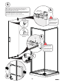
3
A. Place the bracket 1/4" from the top of the L-profi le and align it as shown.
Mark the position of the holes.
B. Drill the holes.
C. Fasten the positioning block.
D. Measure the distance between the shower walls, substract 1 3/4".
E. Cut the track excess according to the measurement taken before.
F. Fix the bracket to the insert with the set screw.
A. Placer le support 1/4 po du haut du profi l en L et l'aligner comme
montré. Marquer la position des trous.
B. Percer les trous.
C. Visser le bloc de positionnement.
D. Mesurer la distance de mur à mur et soustraire 1 3/4 po.
E. Couper le rail avec la mesure prise auparavant.
F. Fixer le support au bloc de positionnement avec la vis de serrage.
Take this measurement minus 1 3/4"
Prendre cette mesure et soustraire 1 3/4 po
E
B
C
D
F
1/4"
A

10
4
G
A
Level the track from
left to right and front
to back!
Mettre de niveau le
rail de gauche à droite
et d'avant en arrière!
THE LEVELING THE TRACK STEP IS THE
MOST CRITICAL FOR PROPER DOOR
SEALED CLOSING.
LA MISE DE NIVEAU DU RAIL EST L'ÉTAPE
LA PLUS CRITIQUE POUR UNE FERME-
TURE DE PORTE APPROPIÉE.
A. Insert the second bracket on the track.
B. Place the track in place and slide bracket against the wall.
C. Trace a plumb line from the inside face of the threshold cap on the
wall, this will be the reference to position the end block sleeve on the
wall.
D. Align the end block sleeve on the line marked on step C and level the
header. Mark the position of the end block sleeve.
E. Remove the header from the corner block. Take the end block sleeve
with the insert and place if on the previously marked position on the
wall. Mark the holes.
F. Drill the holes and fasten the positionning block.
G. Place the track against the positioning block and slide the bracket
around the positioning block and fi x it with the set screws.
A. Insérer le deuxième support sur le rail.
B. Placer le rail en place et glisser le support contre le mur.
C. Tracer une ligne sur le mur à partir de la face intérieure du bout du
seuil. Cette ligne sert de référence pour positionner le support du rail.
D. Aligner le support avec la ligne tracée en C et mettre de niveau le
rail. Marquer la position du support.
E. Enlever le rail du support. Prendre le support avec le bloc de posi-
tionnement et le placer sur la marque faite précédemment et marquer
la position des trous.
F. Percer les trous et visser le bloc de positionnement.
G. Placer le rail contre le bloc de positionnement, glisser le support
autour du bloc de positionnement et le serrer avec la vis de serrage.
INSIDE VIEW
VUE INTÉRIEURE
E
D
INSIDE VIEW
VUE INTÉRIEURE
C
Use sill for plumb line
Utilisez le seuil pour tra-
cer une ligne au plomb
INSIDE VIEW
VUE INTÉRIEURE
F

11
5
A. To position the pivot, place a mark centered on the
threshold 28 3/4" from the wall opposite the door opening.
B. Place the lower pivot guide on the threshold aligning the
mark and the hole.
Fix it in position with the set screws placed on both sides
of the guide.
A. Pour positionner le pivot, placer une marque au centre
du seuil à 28 3/4 po du mur opposé à l'ouverture de la porte.
B. Aligner le trou du pivot inférieur avec la marque sur le
seuil. Fixer en position avec les vis de serrage sur le deux
côtés du guide.
28 3/4"
INSIDE VIEW
VUE INTÉRIEURE
B
INSIDE VIEW
VUE INTÉRIEURE
28 3/4"
28 3/4" FROM WALL TO PIVOT HOLE
28 3/4" DU MUR AU TROU DU PIVOT
A

12
6
B
C
D
Door closing on left
Fermeture de porte à gauche
Holes
Trous
Pivot must be installed
perpendicular with the
door.
Le pivot doit être installé
perpendiculairement avec
le dessus de la porte.
Door closing on right
Fermeture de porte à droite
A. Assemble pivot on top oblong holes of the glass door.
B. Assemble pivot on bottom round holes of the glass door.
C. Insert the defl ector in the bottom of the glass door.
D. Install handle on door as shown.
A. Assembler le pivot dans les trous oblongs du haut de la porte.
B. Assembler le pivot dans les trous ronds du bas de la porte.
C. Insérer le défl ecteur sur le bas de la porte.
D. Installer la poignée sur la porte comme montré.
A
Oblogn slots
Fentes oblongues
Pivot must be installed
perpendicular with the
door.
Le pivot doit être installé
perpendiculairement avec
le dessus de la porte.

13
7
A. Place the lower pivot guide (choose right or left bushing for door opening
as shown).
A. Assembler le pivot sur la base avec la pièce qui vennait avec la porte
(choisir la bague gauche ou droite pour l'ouverture de la porte tel que montré).
A
Pivot
NOTE: Choose bushing accor-
ding to desired door opening.
NOTE: choisir la bague par
rapport à l'ouverture de porte
choisie.
NOTE: The arrows under
the bushing must be facing
outside the shower.
NOTE: les fl èches sous la
bague doivent pointer vers
l'extérieur de la douche.
DOOR OPENING TO THE
LEFT
OUVERTURE DE PORTE
À GAUCHE
DOOR OPENING TO THE
RIGHT
OUVERTURE DE PORTE
À DROITE

14
8
A. Insert glass door starting with the bottom pivot.
B. Loosen setscrew for adjustment. Level the door and fasten with setscrew.
C. Insert gasket on the edge of the door as shown. Trim excess as needed.
A. Installer la porte comme montré.
B. Mettre la porte de niveau et visser avec les vis de serrage sur le rail.
C. Insérer le joint sur le bord de la porte comme montré. Couper l'excès au
besoin.
A
B
C

15
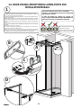
9
A. To determine the positioning of the magnetic wall jamb
place magnetize it on the door. Put the door parallel to the
threshold. Then draw a line on the wall at that location.
B. Place the wall channel aligned with the previously
marked line, level and fasten with screws.
C. Insert magnetic gasket as shown.
D. Fix in position the pivot bracket to the track with the
selftapping screw.
A. Pour déterminer le positionnement du montant ma-
gnétique mural, aimenter celui-ci sur la porte. Mettre la
porte parallèle avec le seuil. Tracer ensuite une ligne sur
le mur à cet endroit.
B. Aligner le rail de la porte sur la marque tracée précé-
demment. Niveler le rail et visser avec les vis.
C. Insérer le montant magnétique comme montré.
D. Fixer le bloc du pivot avec les vis autotaraudeuses.
C
B
DOOR INSTALLATION FINISHED!
INSTALLATION DE PORTE FINIE!
INSIDE VIEW
VUE INTÉRIEURE
INSIDE VIEW
VUE INTÉRIEURE
D
A
INSIDE VIEW
VUE INTÉRIEURE
Pre-assemble
the magnets to
trace the line.
Pré-assembler
les aimants pour
tracer la ligne.

16
2.2. DOOR CLOSING ON WALL
|
FERMETURE SUR LE MUR
1
A. Place the threshold with end cap on the base against the wall. Mark the
threshold as shown.
B. Cut the threshold on the previously done mark.
C. Remove tape fi lm under the threshold.
D. Insert the threshold in the guide. Lower the assembly in position on the
base parallel to the outside edge of the base.
E. Apply a bead of silicone under the cap and place it on the threshold edge.
A. Placer le seuil avec le capuchon sur la base contre le mur. Marquer le seuil
comme montré.
B. Couper le seuil en utilisant la mesure prise précédemment.
C. Enlever la pellicule en-dessous du seuil.
D. Insérer le seuil dans le guide. Baisser l'assemblage en place sur la base
parallèle à la face extérieure de la base.
E. Appliquer de la silicone en dessous du capuchon et le positionner au bout
du seuil.
A
B
D
C
E
(NOT RECOMMENDED) (NON RECOMMANDÉ)

17
2
A
B
C
D
A
Use sill for plumb line
Utilisez le seuil pour tra-
cer une ligne au plomb
INSIDE VIEW
VUE INTÉRIEURE
E
Cut on the right side
of the track to keep
the holes to fasten to
corner block
Couper le bon côté
du rail pour garder les
trous qui vont visser
dans le bloc en coin.
Cut on the right side
of the track to keep
the holes to fasten to
corner block
Couper le bon côté
du rail pour garder les
trous qui vont visser
dans le bloc en coin.
A.Take the measurement from the base threshold to the already ins-
talled block. Place the other block at the height taken and on top of the
L-profi le and align it as shown. Mark the position of the holes.
B. Drill the holes.
C. Fasten the positioning block.
D. Measure the distance between the corner block and the positioning
block, substract
1/2".
E. Cut the track excess according to the measurement taken before.
F. Fix the bracket to the insert with the set screw.
A. Prendre la distance entre le seuil de la base et le support déjà installé.
Placer l'autre support à la même hauteur et au-dessus le profi l en L et
l'aligner comme montré. Marquer la position des trous.
B. Percer les trous.
C. Visser le bloc de positionnement.
D. Mesurer la distance entre le bloc en coin et le bloc de positionnement
soustraire 1/2 po.
E. Couper le rail avec la mesure prise auparavant.
F. Fixer le support au bloc de positionnement avec la vis de serrage.
Take this measurement minus 1/2"
Prendre cette measure et soustraire 1/2 po
A
A

18
3
C
A
Level the track from
left to right and front
to back!
Mettre de niveau le
rail de gauche à droite
et d'avant en arrière!
THE LEVELING THE TRACK STEP IS THE
MOST CRITICAL FOR PROPER DOOR
SEALED CLOSING.
LA MISE DE NIVEAU DU RAIL EST L'ÉTAPE
LA PLUS CRITIQUE POUR UNE FERMETURE
DE PORTE APPROPIÉE.
A. Insert bracket on the track.
B. Insert track in corner block.
C. Slide the bracket on the track against the wall and fi x it to the
positionning block with the set screws.
A. Insérer le support sur le rail.
B. Insérer le rail dans le bloc en coin.
C. Glisser le support sur le rail contre le mur et le fi xer au bloc de
positionnement avec la vis de serrage.
B

19
4
A. To position the pivot, place a mark centered on the threshold 28
3/4
" from the shower wall opposite from the return panel.
B. Place the lower pivot guide on the threshold aligning the mark
and the hole.
Fix it in position with the set screws placed on both sides of the
guide.
A. Pour positionner le pivot, placer une marque centrée sur le seuil
à 28 3/4" du mur de douche opposé au panneau de retour.
B. Placer le guide du pivot inférieur sur le seuil en alignant la
marque et le trou du guide. Fixer en position avec les vis de
serrage sur le deux côtés du guide.
INSIDE VIEW
VUE INTÉRIEURE
INSIDE VIEW
VUE INTÉRIEURE
B
28 3/4"
28 3/4"
28 3/4" FROM WALL TO PIVOT HOLE
28 3/4" DU MUR AU TROU DU PIVOT
A

20
5
B
C
D
Door closing on left
Fermeture de porte à gauche
Holes
Trous
A
Oblogn slots
Fentes oblongues
Pivot must be installed
perpendicular with the
door.
Le pivot doit être installé
perpendiculairement avec
le dessus de la porte.
Pivot must be installed
perpendicular with the
door.
Le pivot doit être installé
perpendiculairement avec
le dessus de la porte.
Door closing on right
Fermeture de porte à droite
A. Assemble pivot on top oblong holes of the glass door.
B. Assemble pivot on bottom round holes of the glass door.
C. Insert the defl ector in the bottom of the glass door.
D. Install handle on door as shown.
A. Assembler le pivot dans les trous oblongs du haut de la porte.
B. Assembler le pivot dans les trous ronds du bas de la porte.
C. Insérer le défl ecteur sur le bas de la porte.
D. Installer la poignée sur la porte comme montré.
La page est en cours de chargement...
La page est en cours de chargement...
La page est en cours de chargement...
La page est en cours de chargement...
La page est en cours de chargement...
La page est en cours de chargement...
La page est en cours de chargement...
La page est en cours de chargement...
La page est en cours de chargement...
La page est en cours de chargement...
La page est en cours de chargement...
La page est en cours de chargement...
La page est en cours de chargement...
La page est en cours de chargement...
La page est en cours de chargement...
La page est en cours de chargement...
La page est en cours de chargement...
La page est en cours de chargement...
La page est en cours de chargement...
La page est en cours de chargement...
-
 1
1
-
 2
2
-
 3
3
-
 4
4
-
 5
5
-
 6
6
-
 7
7
-
 8
8
-
 9
9
-
 10
10
-
 11
11
-
 12
12
-
 13
13
-
 14
14
-
 15
15
-
 16
16
-
 17
17
-
 18
18
-
 19
19
-
 20
20
-
 21
21
-
 22
22
-
 23
23
-
 24
24
-
 25
25
-
 26
26
-
 27
27
-
 28
28
-
 29
29
-
 30
30
-
 31
31
-
 32
32
-
 33
33
-
 34
34
-
 35
35
-
 36
36
-
 37
37
-
 38
38
-
 39
39
-
 40
40


MAAX 137937-900-084-000 ModulR 2 Pivot Shower Door Tunnel 36 x 78 in. 8 mm Guide d'installation
- Taper
- Guide d'installation
dans d''autres langues
Documents connexes
-
MAAX 137857-900-084-000 ModulR Pivot Shower Door Corner 48 x 36 x 78 in. 8 mm Guide d'installation
-
-
-
-
-
-
-
-

