La page est en cours de chargement...

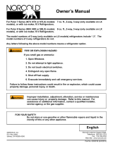
For Polar 7 Series (N7V,N7X or N7LX) models: 7 cu. ft., 2-way, 3-way (only available on LX
models),or with ice maker, R.V Refrigerators.
For Polar 8 Series (N8V,N8X or N8LX) models: 8 cu. ft., 2-way, 3-way (only available on LX
models),or with ice maker, R.V Refrigerators.
The model numbers of 3-way refrigerators (only available on LX models) include “.3”. The
model numbers of 2-way refrigerators do not.
Any letters following the above model numbers means a refrigerator option.
NORCOLD, Inc.
P.O. Box 4248
Sidney, OH 45365-4248
Part No. 639300F (4/1/2020)
English
Installation Manual
Improper installation, adjustment, alteration, service or maintenance can
cause injury or property damage. Refer to this manual. For assistance
or additional information, contact a qualied installer, service agency, or
the gas supplier.
FIRE OR EXPLOSION HAZARD
If you smell gas or ammonia:
1. Open Windows
2. Do not attempt to light appliance.
3. Do not touch electrical switches.
4. Extinguish any open ame.
5. Shut o fuel supply.
6. Evacuate immediately and call emergency services.
Failure to follow these instructions could result in re or explosion, which could cause
property damage, personal injury, or death.
FOR YOUR SAFETY
Do not store or use gasoline or other ammable vapors and liquid in the
vicinity of this or any other appliance.
WARNING
!
WARNING
!
Norcold Customer Support Dept.
Telephone: 800-543-1219
Fax: 734-769-2332
Web Site: www.norcold.com

Installation Manual 2
Table of Contents
Safety Awareness
Safety Instructions
Safety Awareness ..................................................................................................................................................................................... 2
Safety Instructions ....................................................................................................................................................................................2
Certication and Code Requirements.......................................................................................................................................................3
Ventilation Requirements..........................................................................................................................................................................4
Key Refrigerator Dimensions....................................................................................................................................................................5
Assemble the Enclosure for the Refrigerator............................................................................................................................................5
Install the Lower and Upper Vents............................................................................................................................................................6
Rear wall Installation ..............................................................................................................................................................................10
Install the Decorative Door panels (nonmetal door models)...................................................................................................................10
Install the Refrigerator ............................................................................................................................................................................ 11
Reverse the Door Swing-Nonmetal Doors (optional) .............................................................................................................................12
Connect the Electrical Components .......................................................................................................................................................13
Connect the 120 volts AC supply ....................................................................................................................................................13
Connect the 12 volts DC supply ......................................................................................................................................................14
Connect the Propane Gas Components.................................................................................................................................................15
Connect the propane gas supply system ........................................................................................................................................15
Examine the gas supply system for leaks .......................................................................................................................................15
Connect the Icemaker (N7LXIM and N8LXIM models) ..........................................................................................................................16
Connect water supply line ...............................................................................................................................................................16
Operating the Refrigerator Controls (N7V and N8V models) .................................................................................................................17
Ignition and Start Up........................................................................................................................................................................17
Air in the propane gas supply lines .................................................................................................................................................17
Automatic Mode Operations ............................................................................................................................................................ 17
Shut down- all models .....................................................................................................................................................................17
Operating the Refrigerator Controls (N7X and N8X models) .................................................................................................................18
Automatic Mode Operation..............................................................................................................................................................18
Manual AC mode Operation ............................................................................................................................................................ 18
Manual LP Gas Mode Operation ..................................................................................................................................................... 18
Shut down-all models ......................................................................................................................................................................19
Operating the Refrigerator Controls (N7LX and N8LX models) .............................................................................................................19
Automatic Mode Operation..............................................................................................................................................................19
Manual AC Mode Operation ............................................................................................................................................................ 19
Manual LP Gas Operation ............................................................................................................................................................... 20
Manual DC Operation......................................................................................................................................................................20
Shut down-all models ......................................................................................................................................................................20
Fault Codes (N7V and N8V models) ......................................................................................................................................................21
Fault Codes (N7X and N8X models) ......................................................................................................................................................22
Fault Codes (N7LX and N8LX models) ..................................................................................................................................................23
Read this manual carefully and understand the contents before you install the refrigerator.
Be aware of possible safety hazards when you see the safety alert symbol on the refrigerator and in this manual. A signal word follows
the safety alert symbol and identies the danger of the hazard. Carefully read the descriptions of these signal words to fully know their
meanings. They are for your safety.
This Indication means a hazard, which if ignored, can cause dangerous personal injury, death, or property
damage.
This Indication means a hazard, which if ignored, can cause small personal injury or property damage.
- This refrigerator is not approved for use as a free standing refrigerator. It is equipped for the use of propane gas only
and can not be changed to use any other fuels (natural gas, butane, etc.).
- Incorrect installation, adjustment, alteration, or maintenance of this refrigerator can cause personal injury, property
damage, or both. Warranty on the refrigerator is also void.
WARNING
!
WARNING
!
CAUTION
!

Installation Manual 3
- Obey the instructions in this manual to install intake and exhaust vents.
- Do not install the refrigerator directly on carpet. Put the refrigerator on a metal or wood panel that extends the full
width and depth of the refrigerator.
- Do not allow anything from the RV to touch the refrigerator cooling system.
- Propane gas can ignite and cause an explosion that can result in property damage, personal injury, or death. Do not
smoke or create sparks. Do not use an open ame to examine the propane gas supply line for leaks. Always use two
wrenches to tighten or loosen the propane gas supply line connections.
- Make sure the electrical installation obeys all applicable codes. See “Certication and Code Requirements” section.
- Do not bypass or change the refrigerator’s electrical components or features.
- Do not spray liquids near electrical outlets, connections, or the refrigerator components. Many liquids are electrically
conductive and can cause a shock hazard, electrical shorts, and in some cases re.
- The refrigerator cooling system is under pressure. Do not try to repair or to recharge a defective cooling system.
- The cooling system contains sodium chromate. The breathing of certain chromium compounds can cause cancer. The
cooling system contents can cause severe skin and eye burns, and can ignite and burn with an intense ame. Do not
bend, drop, weld, move, drill, puncture, or hit the cooling system.
- The rear of the refrigerator has sharp edges and corners. To prevent cuts or abrasions when working on the
refrigerator, use caution and wear cut resistant gloves.
Certication and Code Requirements
This refrigerator is certied by CSA International as meeting the
latest edition of ANSI Z21.19 / CSA 1.4 standards for installation in
mobile homes or recreational vehicles.
The refrigerator must be installed in accordance with this
“Installation Manual” in order for the Norcold limited warranty to be
in eect. In addition, the installation must conform to the following,
as applicable:
In the United States and Canada:
- Local codes, or in the absence of local codes, the National Fuel Gas Code, ANSI Z223.1/NFPA 54, the Natural Gas and Propane
installation Code, CSA B149.1, ANSI A119.2 Recreational Vehicles Code, and CSA Z240 RV Series, Recreational Vehicles.
- A manufactured home (mobile home) installation must conform with the Manufactured Home Construction and Safety Standard,
Title 24 CFR, Part 3280 [formerly the Federal Standard for Mobile Home Construction and Safety, Title 24 (part 280), and the
current CSA Z240.4, Gas-equipped Recreational Vehicles and Mobile Housing.
- If an external power source is utilized, the appliance, when installed, must be electrically grounded in accordance with local codes
or, in the absence of local codes, the National Electrical code, and ANSI/NFPA 70, or the Canadian Electrical Code, CSA C22.2.
Parts 1 and 2.
All propane gas supply piping and ttings must obey local, state, and national codes about type and size. These components must also
obey the current NFPA 1192 section 2-4, and in Canada with the current CAN 1-6.10 Standard.
Art01290
CAUTION
!

Installation Manual 4
Ventilation Requirements
The completed installation must:
- Make sure there is sucient intake of fresh air for combustion.
- Make sure the living space is completely isolated from the combustion system of the refrigerator.
- Make sure there is complete and unrestricted ventilation of the ue exhaust which, in gas mode, can produce carbon
monoxide. The breathing of carbon monoxide fumes can cause dizziness, nausea, or in extreme cases, death.
- Make sure the refrigerator is completely isolated from its heat generating components through the correct use of
baes and panel construction.
Certied installation needs one lower intake vent and one upper exhaust vent. Install the vents exactly as written in this manual. Any
other installation method voids both the certication and the factory warranty of the refrigerator.
The bottom of the opening for the lower intake vent, which is also the service access door, must be even with or immediately below the
oor level. This allows any leaking propane gas to escape to the outside and not to collect at oor level.
CSA International certication allows the refrigerator to have zero (0) inch minimum clearance at the sides, rear, top, and bottom. While
there are no maximum clearances specied for certication, the following maximum clearances are necessary for correct refrigerator
performance:
Bottom 0 inch min. 0 inch max.
Each Side 0 inch min 1/2 inch max.
Top 0 inch min. 1/4 inch max.
Rear 0 inch min. 1 inch max.
These clearances plus the lower and upper vents cause the natural air draft that is necessary for good refrigeration. Cooler air comes
in through the lower vent, goes up around the refrigerator coils where it removes the excess heat from the refrigerator components, and
goes out through the upper vent. If this air ow is blocked or decreased, the refrigerator will not cool correctly.
Each NORCOLD model is certied by CSA International for correct ventilation. Install only the certied vents that are listed in this
manual.
WARNING
!

Installation Manual 5
Key Refrigerator Dimensions
These key refrigerator dimensions are for your reference as necessary
(See Art02728).
Refrigerator cabinet width w/o trim - 23.47 in. max. ...1
Refrigerator width overall w/ trim - 24.6 in. ................. 2
Refrigerator cabinet to side trim - 0.80 in. ..................3
Refrigerator cabinet height w/o trim............................4
N7 models - 52.85 in. max.
N8 models - 59.85 in. max.
Refrigerator height overall w/ trim...............................5
N7 models - 54.5 in.
N8 models - 61.5 in.
Refrigerator cabinet to top/bottom trim - 0.93 in. ........ 6
Enclosure wall to hinges - 1.10 in. ..............................7
Refrigerator cabinet to center of handles ...................8
N7 models - 32.5 in.
N8 models - 39.5 in.
1. Make sure the enclosure is 59.88 - 60.01 inches high for N8V, N8X, N8LX models or 52.88 - 53.01 inches high for N7V, N7X and
N7LX models x 23.50 - 23.63 inches wide x 24.00 inches deep.
2. Make sure the oor is solid and level.
- The oor must be metal or a wood panel and extend the full width and depth of the enclosure.
- The oor must be able to support the weight of the refrigerator and its contents.
3. Make sure there are no adjacent heat sources such as a furnace vent, a hot water heater vent, etc.
4. If there is more than 1/2 inch between either side of the refrigerator and the inside of the enclosure:
- Fill the space with berglass insulation or add a bae to eliminate the excess clearance.
- Make sure that the rear of the batt-type insulation is between 18 - 19 inches from the face of the enclosure.
- Securely attach the batt-type insulation to the enclosure so that it remains in this position during refrigerator installation, if it
becomes wet, and in windy conditions.
Assemble the Enclosure for the Refrigerator
4
6
8
5
2
3
7
1
Art 02728

Installation Manual 6
Install the Lower and Upper Vents
1. Using the following chart, decide which vents and rough opening (RO) sizes to use:
Certied Vent P/N RO Height RO Width
Upper Roof Exhaust Cap 622293 N/A N/A
Upper Roof Exhaust Vent 616319 24 in. 5 1/4 in.
Upper Exhaust & Lower Intake 621156 / 637615 13 3/4 + 1/8-0in 21 1/2 + 1/8-0in
Lower Square Corner Intake 616010 13 5/8 in. 21 5/8 in.
The RO must be square. Diagonal measurements of the RO should be within 1/16 in. The vent should be centered in the RO width.
2. Install the lower intake vent (See Art 02639, Art 02640, and Art 02638):
The lower intake vent is also the service access opening for the
components on the rear of the refrigerator.
Make sure the bottom of the opening of the lower intake
vent is even with or immediately below the oor level. This
allows any leaking propane gas to escape to the outside
and not to collect at oor level.
- Make sure the bottom of the opening of the lower intake vent [9] is even with or
immediately below the oor level.
- Align the lower intake vent vertically below the coils [10] and the condenser [11]
of the refrigerator.
3. Install the upper exhaust vent:
Make sure that no sawdust, insulation, or other construction
debris is on the refrigerator or in the enclosure. Debris can
cause a combustion hazard and prevent the refrigerator from
operating correctly.
Tighten the screws of the upper roof exhaust cap to 10 inch-pounds
max. Also make sure that the air ow around the upper roof exhaust
cap is not blocked or decreased by other roof mounted features such
as a luggage carrier, an air conditioner, a solar panel, etc.
- If the design of the vehicle allows, install the roof exhaust vent [12] directly
above the condenser [11] of the refrigerator (See Art 02639):
- Install a bae [13] to prevent stagnant hot air in the area [14] above the
refrigerator.
- Make sure there is less than 1/4 inch clearance [15] between the bae
and the top of the refrigerator.
- Make sure the bae is the full width of the inside of the enclosure.
- If the design of the vehicle does not allow you to install the roof exhaust vent directly above the condenser [11] of the refrigerator
(See Art02640):
- Align the roof exhaust vent [12] above the condenser [11] of the refrigerator and move it inboard as necessary.
- Install two baes [13] to prevent stagnant hot air in the area [14] above the refrigerator.
NOTICE
WARNING
!
NOTICE
CAUTION
!
Art 02638
10
9
11

Installation Manual 7
- Make sure the baes are the full width of the inside of the enclosure.
- Make sure that the baes are no more than 45° from vertical [20].
- Put one bae between the top rear edge of the refrigerator and the inside edge of the upper exhaust vent opening.
- Put the other bae between the outside edge of the upper exhaust vent opening and the side wall of the vehicle.
- If the depth of the enclosure is 24 inches or more and is less than 25 inches, no baes are necessary at the rear of the enclosure.
- If the depth of the enclosure is 25 inches or more and is less than 26 inches, add two baes [16] to the rear of the enclosure (See
Art02639 and Art02640).
- Put one bae 18 inches to 18 1/2 inches above the bottom of the enclosure [17] (4 1/4 inches to 4 3/4 inches above the top of
the lower intake vent opening REF) [18] .
- Put the other bae at the lowest edge of the condenser [11] of the refrigerator.
- Make sure that the baes are 1 inch or less [19] from the coils [10] and condenser of the refrigerator.
- Make sure that the baes are the full width of the inside of the enclosure.
Art 02639
15
13
16
15
14
12
11
19
9
18
17
10
16
16
19
14
20
12
19
18
17
9
Art 02640
10
11
13
16

Installation Manual 8
- If the depth of the enclosure is more than 26 inches, install a wood or an aluminum or galvanized sheet solid box bae [21] in the
rear of the enclosure (See Art 02641 and Art 02642).
- Make sure that the bottom of the solid box bae is 18 inches to 18 1/2 inches above the bottom of the enclosure [17] (4 1/4
inches to 4 3/4 inches above the top of the lower intake vent opening REF) [18].
- Make sure that the back of the solid box bae is perpendicular to the bottom of the enclosure.
- Make sure that the back of the solid box bae is either against the top of the enclosure or against the angled bae [13]
(depending on the vehicle design).
- Make sure that the solid box bae is one inch or less [19] from the coils [10] and condenser of the refrigerator.
- Make sure that the solid box bae is the full width of the inside of the enclosure.
- If the design of the vehicle does not allow you to install a roof exhaust vent, install an upper side-wall exhaust vent.
The refrigerator is 23.7 in. min. to 24.0 in. max. from the rear of the breaker to the rear of the condenser [22].
N7V, N7X, N7LX, models are 47.1 in. min. to 47.4 in. max. from the bottom of the refrigerator to the bottom of the
refrigerator condenser [23]. (See Art 02643)
N8V, N8X, N8LX models are 54.1 in. min. to 54.4 in. max. from the bottom of the refrigerator to the bottom of the
refrigerator condenser [23] (See Art 02643).
NOTICE
Art 02641
15
13
14
12
9
17
19
11
10
21
18
19
14
20
12
10
18
17
9
Art 02642
11
13
21

Installation Manual 9
Only use an upper side-wall exhaust vent on refrigerator models that
are equipped with a fan. If you use an upper side-wall exhaust vent
on a refrigerator model that is not equipped with a fan, the refrigerator
cooling performance will be poor.
- Make sure the refrigerator model is equipped with a fan.
- Install the upper side-wall exhaust vent [24] (See Art 02644 and Art 02645).
- For N7V, N7X,and N7LX models, make sure the distance [25] from the bottom
of the enclosure to the top of the rough opening for the upper exhaust vent is at
least 55 inches.
- For N8V, N8X, and N8LX models, make sure the distance [25] from the bottom
of the enclosure to the top of the rough opening for the upper exhaust vent is at
least 62 inches.
- Align the upper exhaust vent [24] horizontally above the lower intake vent [9] of
the refrigerator.
- To prevent stagnant hot air in the area above the refrigerator, install an aluminum
or galvanized steel sheet bae [13] between the top of the refrigerator and the
top of the upper exhaust vent.
- Make sure there is less than 1/4 inch clearance between the bae and the
top of the refrigerator and that the bae overlaps the refrigerator 1 inch or
less.
CAUTION
!
Art 02643
23
22
Art 02644
9
27
10
13
15
25
24
26
11
213
115
15
10
15
13
Art 02645
27
17
25
24
18
21
11
213
9
115

Installation Manual 10
The doors are made to accept decorative panels. The decorative panels must be 3/16 inch or less in thickness. Install
the decorative door panels in the refrigerator doors before installing the refrigerator in the vehicle.
- Make an upper door panel that is 21 19/32 inches wide x 15 17/32 inches high.
- Make a lower door panel that is:
- 21 19/32 inches wide and
- 32 5/8 inches high (for N7 models) or
- 39 5/8 inches high (for N8 models).
- Pull the panel retainer [37] o each door (See Art02624).
- Push the decorative door panel [38] into the slots of the door [39].
- Push each panel retainer into the slot on the edge of the door.
Install Decorative Door Panels
- Make sure that the bae is against the wall of the vehicle at the top of the upper exhaust vent and 1/4 inch or less
from the top of the opening for the upper exhaust vent [115].
- Make sure the bae is the full width of the inside of the enclosure.
- When using an upper side-wall exhaust vent:
- If the depth of the enclosure is 24 inches or more and is less than 26 inches [27], install a bent aluminum or galvanized steel
sheet bae [26] to the rear of the enclosure (See Art 02644).
- Make sure that the bend of the bae is the full width of the inside of the enclosure.
- Make sure that the bend of the bae is ush with the bottom edge of the upper intake vent door frame.
- Make sure that the top edge of the bae is 1/4 inch [213] below the bottom of the condenser and that there is 1/4 inch or
less clearance [115] between the rear of the condenser and the bae.
- If the depth of the enclosure is more than 26 inches [27], install a wood or an aluminum or galvanized steel sheet solid box
bae [21] between the lower intake vent and the upper exhaust vent (See Art 02645).
- Make sure that the solid box bae is the full width of the inside of the enclosure.
- Make sure that the bottom of the solid box bae is 18 inches to 18 1/2 inches above the bottom of the enclosure [17] (4
1/4 inches to 4 3/4 inches above the top of the lower intake vent opening REF) [18] .
- Make sure that the back of the solid box bae is perpendicular to the bottom of the enclosure.
- Make sure that the horizontal top of the solid box bae is even with the bottom edge of the upper exhaust vent [24].
- Make sure that the horizontal top edge of the bae is between 1/2 inch [213] or less below and 1/4 inch or less behind the
lower rear corner of the condenser.
- Make sure that there is 1/4 inch or less clearance [115] between the rear of the condenser and the bae.
NOTICE
Art 02624
37
39
38
Rear wall Installation
For rear wall installations please refer to special instructions 620918 for additional required instructions.

Installation Manual 11
Put the refrigerator in position (See Art 02646, Art 02625 and Art 02626):
Make sure the combustion seal [28] is not broken, is completely
around the refrigerator mounting anges, and is between the
mounting anges and the wall of the enclosure. If the seal is not
complete, exhaust fumes can be present in the living area of the
vehicle. The breathing of exhaust fumes can cause dizziness,
nausea, or in extreme cases, death.
Do not tilt refrigerator into enclosure as damage to enclosure or refrigerator
could occur.
- Push the refrigerator completely into the enclosure.
- Put screws [41] through the upper mounting bracket of the refrigerator and into the
enclosure wall. Snap plastic trim piece [40] into the upper mounting brackets.
Do not omit the bottom trim piece. This piece is part of the
combustion seal.
- Push the bottom trim piece [29] onto the front of the refrigerator.
- Put two screws [41] through the bottom trim piece, the mounting ange, and into the oor.
- Put screws through mounting ange on the rear of the refrigerator and into the oor.
Install the Refrigerator
WARNING
!
WARNING
!
Art 02625
41
40
41
29
Art 02626
Art 02646
28
NOTICE

Installation Manual 12
This refrigerator has cabinet hinges that allow you to change the direction the door opens by moving the hinges to the opposite side. It
is recommended this be done before installing the refrigerator into the enclosure.
1. Remove the doors (See Art 02637):
- Remove the storage bins from the doors.
Do not mix the upper and lower hinge pins because they are dierent.
- Remove and save the upper hinge pin [63] from each hinge.
- Pull the door latch and remove each door from the refrigerator.
- Remove and save the lower hinge pin [64] from each hinge.
2. Change the position of the cabinet hinges and the strike plate and remove the control housing.
(See Art 02631) and (Art 02729):
- Remove and save the screws from the strike plate and hole cover.
- Remove center hinge [363] and screws.
- Flip center hinge [363a] over and reinstall on other side of cabinet.
- To expose the upper hinge, pull up on the outside edge of the hinge cover [369] and lift up and free of the hinge.
- Remove and save the screws from the upper cabinet hinge [66].
- Put the hinge on the other side of the refrigerator [66a].
- Attach the hinge with screws.
- To reinstall the hinge cover [369], bend the outside edge of the hinge
cover and tuck the back end ap between the plastic side trim and
the metal breaker. Push down so tab at front of hinge cover snaps
into slot in top bracket [370]. Press rmly along the outside edge of
the hinge cover and make sure the foam tape is in place. (See Art
02729)
Do not omit the hinge covers or foam tape.
These are part of the combustion seal.
- Tilt the cabinet to the side to allow access to the bottom hinge screws.
- Remove and save the screws from the lower cabinet hinge [67].
- Put the hinges on the other side of the refrigerator [67a]. Insure that the plastic
hinge support is on the refrigerator’s bottommost hinge and the plastic spacer is
placed on the bottom door lower hinge pin.
- Attach the hinge with screws.
- Install strike plate and hole cover with screws on the other side of control.
- Rotate the control housing 180° and put it on the opposite side of the controls (See
Art 02636 & Art 02635).
- Snap the control housing to the refrigerator.
Reverse the Door Swing (optional)
NOTICE
Art 02631
66
66a
67a
67
363
363a
64
67
Art 02637
63
66
369
ART 02729
369
370
WARNING
!

Installation Manual 13
3. Change the position of the door handles (See Art 02630):
- Remove the screws, [41] door handle, [70] latch pin [363] and spring [362] from each door.
- Put the lower door handle on the upper door and the upper door handle on the lower door.
- Attach each door handle with the screws.
4. Reinstall the doors (See Art 02637):
- Turn the lower hinge pins into the lower cabinet hinges.
To prevent damage to the threads of the hinge pins, turn the hinge pins by hand
until tight and then tighten with a screwdriver.
Apply Loctite removable thread locker (blue) to the threads of the hinge
screws before assembly to prevent loosening during use. Do not allow
Loctite to contact any of the plastic surfaces of the refrigerator because it
can damage those surfaces.
- Put each door down onto the lower hinge pin.
- Align the holes in the upper hinges and hold in this position.
- Turn the upper hinge pin into the hinges of each door.
- Tighten the hinge pins.
- Put the storage bins in the doors.
NOTICE
CAUTION
!
70
41
Art 02630
363
362
Art 02635
Art 02636
Connect the Electrical Components
AC Operation 120 volts AC voltage (132 volts max. - 108 volts min.)
DC Operation 12 volts DC control voltage (16.0 volts max. - 10.5 volts min.)
This refrigerator operates on these electrical sources. Operation out of these limits may damage the refrigerator’s electrical circuit
parts and will void the warranty.
The rear of the refrigerator cooling system has hot surfaces and sharp surfaces that can damage electrical
wiring. Make sure that there is a good clearance between all electrical wiring and the cooling system of the
refrigerator. Position any electrical wiring within the refrigerator enclosure opposite the burner side of the
refrigerator. Do not put any electrical wiring through the roof exhaust vent. Failure to correctly position
electrical wiring can result in electrical shock or re.
Connect the 120 volts AC supply:
Connect the AC power cord(s) only to a grounded three-prong receptacle. Do not remove the round
ground prong from any of the AC power cords. Do not use a two prong adapter or an extension cord with
any of the AC power cords. Operation of the refrigerator without correct ground can cause dangerous
electrical shock or death if you are touching the metal parts of the refrigerator.
Put the AC power cord(s) into a grounded three-prong receptacle:
- Make sure the receptacle is positioned within easy reach of the lower intake vent.
- Make sure the power cord(s) does not touch the burner cover, the ue pipe, or any hot component that could damage the insulation
of the power cord.
WARNING
!
WARNING
!

Installation Manual 14
Connect the 12 volts DC supply:
As the distance from the vehicle battery to the refrigerator increases, the correct AWG wire size and fuse size also increases. If the
wire size is too small for the distance, a voltage drop occurs. The voltage drop decreases the DC input voltage to the main control
board which could then aect cooling performance.
1. Determine the min. wire size and the max. fuse size to use:
If you use an incorrect wire size and/or fuse size, electrical re can result.
- On 2-way models, use a minimum of 18 AWG wire and a maximum 6 Amp fuse.
- On 3-way models, measure the distance from the vehicle battery to the refrigerator.
- If the distance is 0 - 20 feet, use a minimum of 10 AWG wire and a maximum 30 Amp fuse.
- If the distance is over 20 feet, use a minimum of 8 AWG wire and a maximum 40 Amp fuse.
- If the wire size is larger than the min. size, use the correct fuse per RVIA A119.2 standard or local codes.
2. Install a fuse in DC power supply wires between the battery and the refrigerator:
- Put fuse as close to the battery as possible.
3. Connect the DC power supply wires (See Art 02763):
- Attach a 1/4 inch Quick Connect terminal to each DC power supply wire.
- Push the positive DC power wire onto the power board terminal that is marked 12VDC [288].
- Push the DC ground wire onto the power board terminal that is marked GND [287].
- Make sure each DC power supply wire is on the correct polarity terminal.
Do not use the chassis of the refrigerator or the vehicle frame as one of the conductors. Attach the DC power supply
wires only to the battery and the main control board input terminals [287 & 288].
WARNING
!
NOTICE
ART 02763
287
288

Installation Manual 15
Connect the Propane Gas Components
This refrigerator operates on propane gas at a pressure of 11 inches Water Column Propane.
Connect the propane gas supply system:
Be very careful when working on or near the propane gas system.
- Do not smoke, or use an open ame near the propane gas system.
- Do not use an open ame to examine for leaks.
- Do not connect the refrigerator to the propane gas tank without a pressure regulator between them.
- To avoid a propane gas leak, always use two wrenches to tighten or loosen the propane gas supply line
connections.
- Leaking propane gas leak can ignite or explode and result in dangerous personal injury or death.
Connect the gas supply line to the refrigerator:
- Make sure that all tubing and ttings obey all local, state, and national codes about size and type.
- Make sure that all exible metal connectors obey the current CAN1-6.10 Standard.
- Make sure that the materials used for the gas supply line obey both the current ANSI A 119.2 (NFPA 1192) and CSA Z240
Standards on Recreational Vehicles. Norcold recommends the use of 3/8 inch copper tubing as the gas supply line and requires a
3/8 inch SAE (UNF 5/8-18) male are tting as the connection to the refrigerator.
- Put the propane gas supply line up through the oor of the enclosure.
- Make sure the hole through the oor is large enough allow clearance for the gas supply line.
- Put a weather resistant seal (grommet, sealant, etc.) around the gas supply line where it goes through the oor to prevent vibration
and abrasion.
- To prevent vibration and abrasion, make sure that the gas supply line is not against anything in the enclosure.
- Attach the gas supply line to the bulkhead tting of the refrigerator.
Examine the gas supply system for leaks:
Do not allow the leak detecting solution to touch the electrical components. Many liquids are electrically
conductive and can cause electrical shorts and in some cases, re.
Use a leak detecting solution to examine the gas supply line and all propane gas connections for leaks.
If you use compressed air for the test:
- The pressure of the compressed air at the manual shut o valve of the refrigerator must not be more than 1/2 psig (14 inches Water
Column).
- If the pressure of the compressed air is more than 1/2 psig (14 inches Water Column), remove the gas supply line from the
bulkhead tting of the refrigerator before the test.
- If the pressure of the compressed air is equal to or less than 1/2 psig (14 inches Water Column), close the manual shut o valve of
the refrigerator before the test.
WARNING
!
WARNING
!

Installation Manual 16
Connect the water supply line:
Install a 1/4 in. OD water supply line [43] from the water shut o valve of the vehicle to the solenoid water valve [44] at the rear of the
refrigerator (See Art 01014):
A brass compression nut [45], a brass sleeve [47], a plastic sleeve [46] , and a brass insert [47] are supplied and
attached to the rear of the refrigerator (See Art 01755).
- Put the compression nut and then the sleeve onto the water supply line [43].
- For copper tubing, use the brass sleeve [47].
- For plastic tubing, use the plastic sleeve [46].
- For plastic tubing with .040 in. wall thickness, also use the brass insert [47].
- Flush the water supply line until the water is clear.
- Put the tubing [43] into the water valve [44] until it is against the stop.
- Tighten the compression nut by hand (hard nger tight).
- Using two wrenches, tighten the compression nut 1 ½ to 2 turns.
- Open the water shut o valve of the vehicle.
- Examine the connections for leaks.
43
44
45
48
Art01014
NOTICE
The ice maker may be assembled to the refrigerators at the factory.
The refrigerator installer must connect a cold water supply line to the solenoid valve at the rear of the refrigerator. The following are
necessary to connect the ice maker:
- 1/4 in. OD copper tubing for the water supply line.
OR
- 1/4 in. OD plastic tubing for the water supply line.
- 1/4 in. shut o valve in the water supply line. This should be easily accessible through the lower intake vent.
Connect the Ice Maker (N8LXIM, and N7LXIM models)
47
46
45
43
ART 01755

Installation Manual 17
Operating the Refrigerator Controls (N7V & N8V Models)
Ignition and start up:
Control boards are extremely sensitive. Evidence of tampering or removal from protective case
will VOID any warranty.
Before ignition or start up of the refrigerator :
- Make sure the air ow in the lower intake vent , through the refrigerator coils and condenser, and out the upper
exhaust vent is not blocked or decreased.
- Make sure there are no combustible materials in or around the refrigerator.
- Make sure the DC voltage to the refrigerator is 12.0VDC
Air in the propane gas supply lines
For safety reasons,the refrigerators electronic controls are designed such that while operating in the LP GAS mode, the
trial for ignition (maximum amount of the time the gas valve and igniter can be left on without a ame present) is limitied
to 30 seconds. When starting the refrigerator for the rst time, after storage, or after replacing the propane gas tank, the
propane gas supply lines can have air in them.
Due to air in the gas supply lines, the burner may not ignite within the 30 second time limit. In the event this
should happen the gas valve and igniter outputs will be turned o, the LP Gas mode will be “locked out”,
and the appropiate fault code will be shown in the display. See fault code section of this manual.
The gas lock out condition can be reset by powering the refrigerator OFF and then back ON, at which
time, a new 30 second trial for ignition will commence. It may be necessary to repeat this procedure 2 to
3 times before expelling all the aor from the LP gas supply line. If after repeated attempts, a ame is not
established, stop and cosult your local dealer or Authorized Norcold Service Center.
Automatic mode operation:
- Touch and release the ON / OFF button [30] to turn the
refrigerator on.(See Art 02628)
- If the indicator light [185] glows solid green, it means:
- 120 volt AC power is available to the refrigerator.
- The refrigerator is operating on AC electric power.
- If the indicator light [185] glows solid amber, it means:
- 120 volt AC power is not available to the refrigerator.
- The refrigerator is operating on propane gas.
- If the indicator light [185] glows solid red, it means:
- There is a problem and the refrigerator is not cooling.
- Refer to the “Fault Code” section of this manual.
Shut down - All models:
- To shut down the refrigerator, touch and hold the ON/OFF button for two seconds.
NOTICE
Art 02628
30
185
NOTICE

Installation Manual 18
Automatic mode operation: (N7X and N8X models)
Control boards are extremely sensitive.
Evidence of tampering or removal from
protective case will VOID any warranty.
- Touch and release the ON/OFF button [30] to turn the refrigerator
on.(See Art 02627)
- If the indicator light [185] glows solid green, it means the refrigerator
is operating correctly.
- Touch the TEMP SET button [32] as needed to set the temperature setting.
- One snowake lit up is the warmest setting.
- Five snowkes lit up is the coldest setting.
- If the AUTO icon [277] and AC PLUG icon [283] are lit up, it means that:
- 120 volt AC power is available to the refrigerator.
- The refrigerator is operating on AC electric power.
- If the AUTO icon and the FLAME icon [284] are lit up, it means that:
- 120 volt AC power is not available to the refrigerator.
- The refrigerator is operating on propane gas.
- If the indicator light [185] glows solid red, it means:
- There is a problem and the refrigerator is not cooling.
- Refer to the “Fault Code” section of this manual.
Manual AC Mode Operation:
- Touch and release the ON/OFF button [30] to start the refrigerator.
- Touch the MODE button [31] until the AUTO icon goes o and only the AC PLUG icon [283] remains lit.
- Touch the TEMP SET button [32] as needed, to set the temperature setting.
- The AC PLUG icon remains lit until you select a dierent operating mode or shut down the refrigerator.
- If the indicator light [185] glows solid red, it means:
- There is a problem and the refrigerator is not cooling.
- Refer to the “Fault Code” section of this manual.
Manual LP Gas Mode Operation:
- Touch and release the ON/OFF button [30] to start the refrigerator.
- Touch the MODE button [31] until the AUTO icon goes o and only the FLAME icon [284] remains lit.
- Touch the TEMP SET button [32] as needed, to set the temperature setting.
- FLAME icon [284] remains lit until you select a dierent operating mode or shut down the refrigerator.
- If the indicator light [185] glows solid red, it means:
- There is a problem and the refrigerator is not cooling.
- Refer to the “Fault code” section of this manual.
30
185
NORCOLD
MODE
A
31 32
187
277
283
284
Art 02627
Operating the Refrigerator Controls (N7X & N8X Models)
NOTICE

Installation Manual 19
Shut down - All models:
- To shut down the refrigerator, touch and hold the ON/OFF button for two seconds and then release.
Automatic Mode Operation:
Control boards are extremely sensitive. Evidence of tampering or removal from protective case
will VOID any warranty.
- Touch and release the ON/OFF button [30] to turn the refrigerator on. (See Art 02629).
- Touch the TEMP SET button [32] as needed to set the
temperature setting.
- Number one (1) shown in the display [187] is the warmest
setting.
- Number nine (9) shown in the display [187] is the coldest
setting.
- If the AUTO icon [277] and AC PLUG icon [278] are lit up, it
means that:
- 120 volt AC power is available to the refrigerator.
- The refrigerator is operating on AC electric power.
- After ten seconds, the backlight of the display goes o.
- If the AUTO icon and the FLAME icon [289] are lit up, it means that:
- 120 volt AC power is not available to the refrigerator.
- The refrigerator is operating on propane gas.
- After ten seconds, the backlight of the display goes o.
If neither 120 volts AC nor propane gas are available to the refrigerator :
- The fault codes “no AC” and then “no FL” show in the display and an audible alarm sounds.
- Refer to the “Fault Codes” section of this manual for any faults displayed.
If an energy source is available to the refrigerator but is not operating correctly:
- While operating in the Automatic mode, the refrigerators electronic controls will automatically select the energy source using the
following priorit scheme:
1st choice: AC Electric
2nd choice: LP GAS
3rd choice: DC Electric (3-way refrigerators only)
- When in the Auto mode, if a higher priority choice becomes available (i.e., AC voltage reapplied), the control shall stop
using the current mode and switch to the higher priority mode.
Manual AC Mode Operation:
- Touch and release the ON/OFF button [30] to turn the refrigerator on.
- Touch the MODE button [31] until the AUTO icon goes o and only the AC PLUG icon [278] remains lit.
- Touch the TEMP SET button [32] as needed, to set the temperature setting.
- The AC PLUG icon [278] remains lit until you select a dierent operating mode or shut down the refrigerator.
30 31 32
187
277
278
289
AUTO
NORCOLD
MODE
set
CODE
361
Art 02629
Operating the Refrigerator Controls (N7LX & N8LX Models)
NOTICE

Installation Manual 20
Manual LP GAS Operation:
- Touch and release the ON/OFF button [30] to turn the refrigerator on.
- Touch the MODE button [31] until the AUTO icon goes o and only the FLAME icon [289] remains lit.
- Touch the TEMP SET button [32] as needed, to set the temperature setting.
- The FLAME icon [289] remains lit until you select a dierent operating mode or shut down the refrigerator.
Manual DC Operation:
- Touch and release the ON/OFF button [30] to turn the refrigerator on.
- Touch the MODE button [31] until the AUTO icon goes o and only the BATTERY icon [361] remains lit.
- Touch the TEMP SET button [32] as needed, to set the temperature setting.
- The Battery icon [361] remains lit until you select a dierent operating mode or shut down the refrigerator.
Shut down - All models:
- To shut down the refrigerator, touch and hold the ON/OFF button for two seconds and release.
/