BEST BY BROAN P.O. Box 140, Hartford, WI 53027
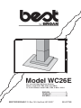
Model WC26E
ENGLISH.....................................2
FRANÇAIS................................15
ESPAÑOL..................................28
For use with Best By Broan Exterior
Blower model EB6, EB9, EB12 and EB15;
Or In-Line Blower model ILB3, ILB6, ILB9 or ILB11
99043778B

- 2 -
READ AND SAVE THESE INSTRUCTIONS
WARNING
TO REDUCE THE RISK OF FIRE, ELECTRIC SHOCK, OR INJURY TO PERSONS,
OBSERVE THE FOLLOWING:
1. Use this unit only in the manner intended by the manufacturer. If you have questions,
contact the manufacturer at the address or telephone number listed in the warranty.
2. Before servicing or cleaning unit, switch power off at service panel and lock service
panel to prevent power from being switched on accidentally. When the service
disconnecting means cannot be locked, securely fasten a prominent warning device,
such as a tag, to the service panel.
3. Installation work and electrical wiring must be done by a qualified person(s) in accor-
dance with all applicable codes and standards, including fire-rated construction codes
and standards.
4. Sufficient air is needed for proper combustion and exhausting of gases through the flue
(chimney) of fuel burning equipment to prevent backdrafting. Follow the heating equip-
ment manufacturer’s guidelines and safety standards such as those published by the
National Fire Protection Association (NFPA), and the American Society for Heating,
Refrigeration and Air Conditioning Engineers (ASHRAE), and the local code authorities.
5. When cutting or drilling into wall or ceiling, do not damage electrical wiring and other
hidden utilities.
6. Ducted fans must always be vented to the outdoors.
7. Do not use this unit with any separate solid-state speed control device.
8. To reduce the risk of fire, use only metal ductwork.
9. This unit must be grounded.
TO REDUCE THE RISK OF A RANGE TOP GREASE FIRE:
A. Never leave surface units unattended at high settings. Boilovers cause smoking and
greasy spillovers that may ignite. Heat oils slowly on low or medium settings.
B. Always turn hood ON when cooking at high heat or when flambeing food (i.e. Crepes
Suzette, Cherries Jubilee, Peppercorn Beef Flambe’).
C. Clean ventilating fans frequently. Grease should not be allowed to accumulate on fan or
filter.
D. Use proper pan size. Always use cookware appropriate for the size of the surface
element.
WARNING
TO REDUCE THE RISK OF INJURY TO PERSONS IN THE EVENT OF A RANGE TOP
GREASE FIRE, OBSERVE THE FOLLOWING:*
1. SMOTHER FLAMES with a close-fitting lid, cookie sheet, or metal tray, then turn off the
burner. BE CAREFUL TO PREVENT BURNS. If the flames do not go out immediately,
EVACUATE AND CALL THE FIRE DEPARTMENT.
2. NEVER PICK UP A FLAMING PAN - You may be burned.
3. DO NOT USE WATER, including wet dishcloths or towels - violent steam explosion will
result.
4. Use an extinguisher ONLY if:
A. You know you have a Class ABC extinguisher and you already know how to operate
it.
B. The fire is small and contained in the area where it started.
C. The fire department is being called.
D. You can fight the fire with your back to an exit.
* Based on “Kitchen Fire Safety Tips” published by NFPA.
!
INTENDED FOR DOMESTIC COOKING ONLY
!

- 3 -
!
CAUTION
1. To reduce risk of fire and to properly exhaust air, be sure to duct air outside. Do not vent
exhaust air into spaces within walls or ceilings or into attics, crawl spaces, or garages.
2. Take care when using cleaning agents or detergents.
3. Avoid using food products that produce flames under the Range Hood.
4. For general ventilating use only. Do not use to exhaust hazardous or explosive mate-
rials and vapors.
5. To avoid motor bearing damage and noisy and/or unbalanced impellers, keep drywall
spray, construction dust, etc. off power unit.
6. Your hood motor has a thermal overload which will automatically shut off the motor if it
becomes overheated. The motor will restart when it cools down. If the motor continues
to shut off and restart, have the hood serviced.
7. For best capture of cooking impurities, the bottom of the hood should be a minimum of
22" and a maximum of 28" above the cooking surface. See “Install Mounting Bracket”
section for mounting restrictions.
8. Two installers are recommended because of the large size and weight of this hood.
9. This product is equipped with a thermostat which may start blower automatically. To
reduce the risk of injury and to prevent power from being switched on accidentally,
switch power off at service panel and lock or tag service panel.
10. Use with approved cord-connection kit only.
11. Please read specification label on product for further information and requirements.
For use with Best by Broan Exterior
Blower model EB6, EB9, EB12 and EB15;
Or In-Line Blower model ILB3, ILB6, ILB9 or ILB11

- 4 -
OPERATION
Controls
The hood is operated using the (5) push buttons located on the front edge of the
hood.
The Light switch turns the halogen lights on and off. Push the light switch once to
turn the lights ON - push a second time to turn the lights ON to a brighter level -
push a third time to turn the lights OFF.
The Glass switch turns the glass light on. Push the glass switch once to turn the
glass light ON - push a second time to turn the light OFF. Depress and hold the
button to activate the automatic light sensor. When the LED Display indicates
“A”, the glass light will automatically light when the room becomes dark. Push a
second time to deactivate the sensor and turn the light off.
The Blower Off/Speed switch turns the blower off and changes blower speed to
four different speed settings: high, medium-high, medium-low and low speed.
Depress and hold the button for 2 seconds to turn the blower off.
The Blower On/Speed switch turns the blower on to four different speed settings:
Low, medium-low, medium-high and high speed.
The LED Display:
- Indicates blower speed selection from 1 (low speed) to 4 (high speed).
- Flashes the blower speed when the 10-minutes delay off has been activated.
- After 30 hours of operation, the center segment of the display blinks and remains
lit, indicating that filters need to be cleaned.
- Indicates “A” when the Light Sensor is ON.
The Time Delay switch activates a delay off feature. When pushed, the blower
will continue to operate at the current speed setting for 10-minutes before
automatically turning itself off.
The Filter Alarm Reset switch is used to reset the 30-hour filter timer. After filters
are cleaned or replaced, press this switch once to reset the filter clean alarm.
HEAT SENTRY™
Your hood is equipped with a HEAT SENTRY™ thermostat. This thermostat is a
device that will turn on or speed up the blower if it senses excessive heat above
the cooking surface.
1) If blower is OFF - it turns blower ON to HIGH speed.
2) If blower is ON at a lower speed setting - it turns blower up to HIGH speed.
When the temperature level drops to normal, the blower will return to its original
setting.
WARNING
The HEAT SENTRY thermostat can start the blower even if the hood is turned
OFF. When this occurs, it is impossible to turn the blower OFF with its switch.
If you must stop the blower, do it from the main electrical panel.
Light Switch
Glass Switch
Blower Off/Speed
Blower On/Speed
LED Display
Time Delay/
Filter Alarm Reset

- 5 -
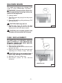
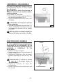
FUSE REPLACEMENT
IF LIGHTS FAIL TO OPERATE, DISCON-
NECT POWER AT THE SERVICE EN-
TRANCE. CHECK THE FUSE AND RE-
PLACE IF NECESSARY.
1. Remove the grease filter.
2. Unscrew the cap from the fuse holder and
remove the fuse.
3. Replace the fuse with the same size and
amperage (5 x 20mm, 4 amp, 125 volt).
!
CAUTION: Use a fuse greater than 4
amps may damage the transformer.
4. Reinstall the fuse holder cap.
5. Reconnect power at the service
entrance.
FUSE
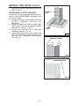
HALOGEN BULBS
This range hood requires two halogen bulbs
(Type T3, 12Volt, 20Watt Max, G-4 Base).
WARNING: Always switch off the elec-
trical supply before carrying out any op-
eration on the appliance.
To change bulbs:
1. Open the cover by prying from the proper
slots. Fig. 2.
2. Remove the bulb by pulling sideways. (DO
NOT ROTATE).
!
CAUTION: Bulb may be hot.
3. Replace with Type T3, 12Volt, 20 Watt
Max, G-4 Base halogen bulb. Do not touch
replacement bulb with bare hands!
!
CAUTION: Use of bulbs greater than
20 watts will cause the fuse to open.
FIG. 2
FIG. 3
GREASE FILTER

- 6 -
MAINTENANCE
Proper maintenance of the Range Hood will assure proper performance of the unit.
Grease Filter
The grease filter should be cleaned frequently. Use a warm detergent solution.
Grease filter is dishwasher safe.
See “INSTALL FILTERS” section for removal and installation instructions.
Hood Cleaning
Stainless steel is one of the easiest materials to keep clean. Occasional care will
help preserve its fine appearance.
Cleaning tips:
● Hot water with soap or detergent is all that is usually needed.
● Follow all cleaning by rinsing with clear water. Wipe dry with a clean, soft cloth to
avoid water marks.
● For discolorations or deposits that persist, use a non-scratching household cleanser
or stainless steel polishing powder with a little water and a soft cloth.
● For stubborn cases, use a plastic scouring pad or soft bristle brush together with
cleanser and water. Rub lightly in direction of polishing lines or "grain" of the
stainless finish. Avoid using too much pressure which may mar the surface.
● DO NOT allow deposits to remain for long periods of time.
● DO NOT use ordinary steel wool or steel brushes. Small bits of steel may adhere
to the surface causing rust.
● DO NOT allow salt solutions, disinfectants, bleaches, or cleaning compounds to
remain in contact with stainless steel for extended periods. Many of these com-
pounds contain chemicals which may be harmful. Rinse with water after expo-
sure and wipe dry with a clean cloth.
Painted surfaces should be cleaned with warm water and mild detergent only.

- 7 -
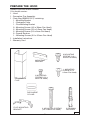
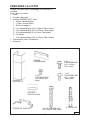
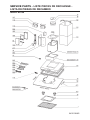
PREPARE THE HOOD
Unpack hood and check contents.
You should receive:
1 - Hood
1 - Decorative Flue Assembly
1 - Parts Bag (B080810747) containing:
1 - Mounting Bracket
1 - Discharge Collar
1 - Flue Mounting Bracket
8 - Mounting Screws (4.8 x 38mm Pan Head)
6 - Mounting Screws (3.9 x 9.5mm Pan Head)
2 - Mounting Screws (3.9 x 6mm Flat Head)
8 - Drywall Anchors
1 - Mounting Screws (2.9 x 9.5mm Pan Head)
1 - Installation Instructions
1 - Warranty Card
MOUNTING
BRACKET
DISCHARGE
COLLAR
FLUE MOUNTING
BRACKET
8 MOUNTING SCREWS
(4.8 x 38mm Pan Head)
8 DRYWALL
ANCHORS
6 MOUNTING
SCREWS (3.9 x
9.5mm Pan Head)
DECORATIVE
FLUE
2 MOUNTING
SCREWS (3.9 x
6mm Flat Head)
1 MOUNTING
SCREW (2.9 x
9.5mm Pan Head)
FIG. 4

- 8 -
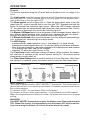
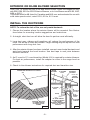
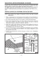
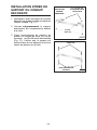
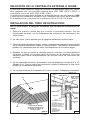
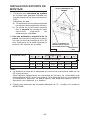
INSTALL THE DUCTWORK
NOTE: To reduce the risk of fire, use only metal ductwork.
1. Choose the location where the exterior blower will be mounted. See illustra-
tions below for mounting location suggestions and restrictions.
2. A straight, short duct run will allow the hood to perform most efficiently.
3. Long duct runs, elbows and transitions will reduce the performance of the
hood. Use as few of them as possible. Larger ducting may be required for best
performance with long duct runs.
4. After the exterior blower has been installed, connect round metal ductwork and
work back towards the hood location. Use duct tape to seal joints between
ductwork sections.
5. An 8” round to 10” round transition (Model 414) is required for exterior blowers.
For best air performance, install the adapter as close to the range hood as
possible.
6. Check In-Line blower instructions for required duct and transition size.
EXTERIOR
BLOWER
10” ROUND
DUCT
HOOD
EXTERIOR
BLOWER
8” TO 10”
ROUND
ADAPTER
8” ROUND
ELBOW
10”
ROUND
DUCT
8” ROUND
DUCT
OK
OK
CAUTION: MAY NOT
FIT UNDER EAVES
OF SINGLE STORY
HOMES
SUGGESTED MOUNTING LOCATIONS
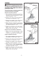
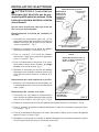
EXTERIOR OR INLINE BLOWER SELECTION
CAUTION: To reduce the risk of fire and electric shock, install this rangehood only
with EB6, EB9, EB12 or EB15 Exterior Blowers, or In-Line Blower model ILB3, ILB6,
ILB9 or ILB11.
The blower must be UL listed for Canadian and U.S. use, and evaluated for use with
solid state speed control, rated 120V, 60 Hz, 6.0 A max.
FIG. 6
FIG. 5
22” TO 28” ABOVE
COOKING SURFACE
(see “INSTALL
MOUNTING BRACKETS”
section for mounting
restrictions
INLINE
BLOWER

- 9 -
BOX
MARKED “120
VAC INPUT”
FIG. 8
!
POWER CONNECTION AT HOOD
CONNECT:
WHITE-TO-WHITE,
BLACK-TO-BLACK,
GREEN-TO-GROUND.
120 Volt 60Hz
LINE-IN
BLOWER CONNECTION AT
HOOD
BOX MARKED
“MOTOR
CONNECTION”
Exterior or
In-Line blower
FIG. 7
CONNECT:
WHITE-TO-WHITE,
RED-TO-BLACK,
GREEN-TO-GROUND.
WIRING
CAUTION: All electrical wiring should
be done by a qualified person (s) in
accordance with all applicable codes and
standards. This range hood must be
properly grounded.
Do not turn power on at service panel until
all wires have been connected.
Blower connection at hood:
1. Run conductors (2-wire plus ground) from
the blower to the hood’s wiring box marked
“motor connection”. Fig. 7
2. Remove the cover from the wiring box
and remove one knockout. Fig. 7
3. Secure the conduit to the wiring box
through a conduit connector. Fig.7
4. Make electrical connections at the hood.
Connect white-to-white, red-to-black
and green-to-ground. Fig.7
5. Replace the wiring box cover and screws.
Make sure wires are not pinched
between the cover and box.
Exterior or In-Line blower connection:
1. Make electrical connections at the
exterior or In-Line blower (see
instructions provided with the blower).
Power connection at hood:
1. Run supply conductors to the hood wiring
box marked “120VAC input”. Fig. 8
2. Remove the cover from the wiring box
and remove one knockout. Fig. 8
3. Secure the conduit to the wiring box
through a conduit connector. Fig. 8
4. Make electrical connections at the hood.
Connect white-to-white, black-to-black
and green-to-ground. Fig. 8
5. Replace the wiring box cover and screws.
Make sure wires are not pinched
between the cover and box.

- 10 -
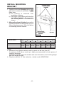
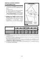
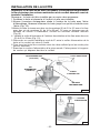
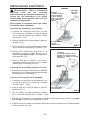
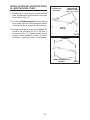
INSTALL MOUNTING
BRACKET
1. Construct wood wall framing that is flush
with interior surface of wall studs. Fig. 9.
Make sure:
a) the framing is centered over
installation location.
b) the height of the framing will allow the
mounting bracket to be secured to
the framing within the dimensions
shown.
2. After wall surface is finished, secure the
mounting bracket to framing with (2) 4.8 x
38mm mounting screws. See chart below
for mounting bracket location.
Notes:
a. Minimum hood distance above cook top must not be less than 22”.
A maximun of 28” above cook top is highly recommended for best capture of
cooking impurities.
Distances over 28” are at the installer and user’s discretion; and if ceiling height
and flue length permits.
b. Requires optional 10’ flue extension, ducted model AEWC26xB.
HOOD DISTANCE ABOVE 36” HIGH COOK TOP (see note a)
28”
MOUNTING BRACKET LOCATION ABOVE 36” HIGH COOK TOP
47-1/4”
CEILING HEIGHT
8-FOOT
9-FOOT
22” 23” 24” 25” 26” 27”
41-1/4” 42-1/4” 43-1/4” 44-1/4”
10- FOOT (see note b)
45-1/4” 46-1/4”
41-1/4” 42-1/4” 43-1/4” 44-1/4”
41-1/4” 42-1/4” 43-1/4” 44-1/4”
47-1/4”45-1/4” 46-1/4”
FRAMING BEHIND
WOOD CROSS
SUPPORT
WOOD CROSS
SUPPORT BEHIND
DRYWALL
DRYWALL
FIG. 9

- 11 -
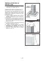
INSTALL FLUE MOUNTING
BRACKET
1. Assemble the flue mounting bracket,
adjusting outside width as shown. Fig.10
2. Carefully center the mounting bracket
directly over the range hood location.
3. Secure the bracket assembly to the ceiling
using (2) 4.8x38mm mounting screws
and drywall anchors (Fig. 11). Make sure
the bracket is pushed into the corner,
tight against the wall and centered over
the hood.
FLUE MOUNTING BRACKET
9-13/16”
(24.9 cm)
FIG.10
3.9 x 6 mm FLAT HEAD
BRACKET SCREWS
FIG.11
4.8x38mm
MOUNTING SCREWS
DRYWALL ANCHORS

- 12 -
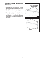
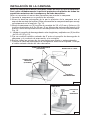
INSTALL THE HOOD
Note: On stainless steel hoods, carefully remove the plastic protective film
from all exterior surfaces of the hood and decorative flues, prior to final
installation.
Note: at least two people will be required to mount the hood.
1. Raise the hood into its mounting position.
2. Align the rectangular opening on the back of the hood with the wall-mounting
bracket. Gently lower the hood until it securely engages the bracket. Fig. 12.
3. Level the hood with (2) 3.9x9.5mm mounting screws and secure with (4)
4.8x38mm mounting screws. Use drywall anchors provided if wall studs or
framing are not available. Fig. 12.
4. Install the discharge collar inside the tabs and secure with (2) 3.9 x 9.5mm screws.
Fig. 13.
5. Attach 8” round metal duct between the hood’s discharge collar and duct that
leads to the blower.
6. Tape all duct joints to make them secure and air tight.
7. Plug the power cord into the electric wall receptacle. Tuck excess cord behind
the flue.
FIG. 12
MOUNTING
SCREWS
(4.8x38mm)
RECTANGULAR
CUTOUT
WALL FRAMING
MOUNTING
BRACKET
MOUNTING SCREWS
(3.9x9.5mm)
DISCHARGE
COLLAR
FIG.13
TABS

- 13 -
2.9x9.5mm
MOUNTING SCREW
FIG.16
LOWER
FLUE
UPPER
FLUE
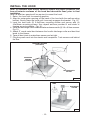
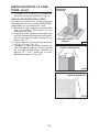
INSTALL THE HOOD, cont’d
7. Carefully place the decorative flue on the
hood. Fig. 14.
ROOMS WITH 10-FOOT CEILINGS
Rooms with 10-foot ceilings require flue ex-
tension model AEWC26xB, available from
your local dealer.
8. Discard the upper flue supplied with the
product. Replace it with the flue
extension.
9. Raise the upper flue until its holes align
with holes in the flue mounting bracket
(located on ceiling). Fig. 15.
10.Secure the flue with (2) 3.9x9.5mm
mounting screws. Fig. 15.
11. Secure the lower flue to the upper flue
with (1) 2.9x9.5mm mounting screw. Drill
the hole (1/16” Diameter) in the upper
flue. Fig. 16.
3.9x9.5mm
MOUNTING SCREWS
FIG.15
FIG.14

- 14 -
WARRANTY
BROAN ONE YEAR LIMITED WARRANTY
Broan warrants to the original consumer purchaser of its products that such products will be free from defects in materials
or workmanship for a period of one year from the date of original purchase. THERE ARE NO OTHER WARRANTIES,
EXPRESS OR IMPLIED, INCLUDING, BUT NOT LIMITED TO, IMPLIED WARRANTIES OR MERCHANT ABILITY OR
FITNESS FOR A PARTICULAR PURPOSE.
During this one-year period, Broan will, at its option, repair or replace, without charge, any product or part which is found to
be defective under normal use and service.
THIS WARRANTY DOES NOT EXTEND TO FLUORESCENT LAMP STARTERS, TUBES, HALOGEN AND
INCANDESCENDT BULBS. This warranty does not cover (a) normal maintenance and service or (b) any products or parts
which have been subject to misuse, negligence, accident, improper maintenance or repair (other than by Broan), faulty
installation or installation contrary to recommended installation instructions.
The duration of any implied warranty is limited to the one-year period as specified for the express warranty. Some states do
not allow limitation on how long an implied warranty lasts, so the above limitation may not apply to you.
BROAN’S OBLIGATION TO REPAIR OR REPLACE, AT BROAN’S OPTION, SHALL BE THE PURCHASER’S SOLE AND
EXCLUSIVE REMEDY UNDER THIS WARRANTY. BROAN SHALL NOT BE LIABLE FOR INCIDENTAL, CONSEQUEN-
TIAL OR SPECIAL DAMAGES ARISING OUT OF OR IN CONNECTION WITH PRODUCT USE OR PERFORMANCE.
Some states do not allow the exclusion or limitation of incidental or consequential damages, so the above limitation or
exclusion may not apply to you.
This warranty gives you specific legal rights, and you may also have other rights, which vary from state to state. This warranty
supersedes all prior warranties.
To qualify for warranty service, you must (a) notify Broan at the address stated below or telephone: 1-800-637-1453, (b) give
the model number and part identification and (c) describe the nature of any defect in the product or part. At the time of requesting
warranty service, you must present evidence of the original purchase date.
BEST BY BROAN, P.O. Box 140 Hartford, Wisconsin 53027
INSTALL FILTERS
1. To remove the GREASE filter, grip the
latch tab and pull it down. This will
disengage the filter from the hood. Tilt the
filter downward and remove. Fig. 17.
2. To install the GREASE filter, align rear
filter tabs with slots in the hood. Pull latch
tab down, push filter into position and
release. Make sure the filter is securely
engaged after installation. Fig.17.
NOTE: Prior to use, remove protective film
from the filter frame.
GREASE FILTER
FIG. 17

- 15 -
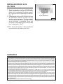
LISEZ ET CONSERVEZ CES INSTRUCTIONS
AVERTISSEMENTS
POUR REDUIRE LES RISQUES D’INCENDIE, DE DECHARGES ELECTRIQUES OU
DE DOMMAGES AUX PERSONNES, OBSERVEZ LES INSTRUCTIONS SUIVANTES:
1. N’utilisez cet appareil que comme cela est indiqué par le constructeur. Si vous avez des
problèmes, contactez le fabriquant à l’adresse ou au numéro de téléphone indiqués dans
la garantie.
2. Avant de pourvoir à l’entretien ou au nettoyage de votre appareil, éteignez-le au tableau
des commandes ou bloquez le tableau des commandes afin d’éviter de le mettre en marche
accidentellement. Si vous ne pouvez pas bloquer le système permettant d’éteindre votre
appareil, appliquez un avertissement extérieur d’une façon sure, comme par exemple un
panneau, sur le tableau des commandes.
3. L’assemblage et la connexion électrique doivent être faits par des personnes qualifiées
en respectant les normes et règlements en vigueur, y compris les normes et règlements
concernant les possibilités d’incendie.
4. Il est indispensable qu’il y ait suffisamment d’air pour que la combustion et l’évacuation des
gaz à travers le tuyau du brûleur du combustible ait lieu sans retour de flamme. Suivez
les indications données par le fabricant du brûleur ainsi que les normes de sécurité comme
celles qui sont publiées par l’Association Nationale pour la Protection contre les Incendies
National Fire Protection Association (NFPA) et la American Society for Heating, Refrigeration
and Air Conditioning Engineers (ASHRAE), et les autorités locales en matière de normes.
5. Quand vous coupez ou percez des trous dans le mur ou le plafond, n’abîmez pas les fils
électriques ou autres.
6. Le ventilateur canalisé doit toujours évacuer l’air vers l’extérieur.
7. N’utilisez pas cet appareil avec un appareil contrôlant la vitesse à état solide.
8. Afin de diminuer tout risque d’incendie n’utilisez que des conduits en métal.
9. Votre appareil doit être relié à la terre.
ATTENTION - POUR REDUIRE LES RISQUES D’INCENDIE DES MATIERES GRASSES
QUI SONT EN TRAIN DE CUIRE:
A. Ne laissez jamais ni vos éléments chauffants, ni vos casseroles ou poêles sur le feu
sans les contrôler si vous réglez l’apport de chaleur sur une position élevée. Si vos
casseroles ou poêles débordent cela provoque de la vapeur et des éclaboussures de
graisse qui peuvent prendre feu. Chauffez les huiles lentement à feu bas ou moyen.
B. Faites toujours fonctionner votre hotte quand vous cuisez à des températures élevées
ou quand vous cuisinez des plats flambés. (par ex. crêpes Suzette, Cerises “Jubilé”,
Steack au poivre flambé).
C. Nettoyez régulièrement les ailes de vos ventilateurs. Ne permettez pas que la graisse
s’accumule sur le ventilateur ou sur le filtre.
D. Utilisez des casseroles de taille appropriée. Utilisez toujours des ustensiles de cuisson
dont la taille est appropriée à la surface de votre élément de cuisson.
AVERTISSEMENTS
POUR REDUIRE LES RISQUES DE DOMMAGES AUX PERSONNES AU CAS OÙ VOTRE
CUISINIERE PRENDRAIT FEU, OBSERVEZ LES INSTRUCTIONS SUIVANTES:*
1. ETEINDRE LES FLAMMES à l’aide d’un couvercle le plus hermétique possible, une
plaque à gâteaux, ou un plateau en métal, puis éteindre le brûleur. ATTENTION à NE
PAS VOUS BRÛLER. Si les flammes ne s’éteignent pas immédiatement, SORTEZ ET
APPELEZ LES POMPIERS.
2. NE PRENEZ JAMAIS EN MAIN UNE POÊLE OU UNE CASSEROLE QUI A PRIS FEU
- Vous pourriez vous brûler.
3. N’UTILISEZ PAS D’EAU, ni torchons ou serviettes mouillés - vous provoqueriez une
violente explosion de vapeur.
SEULEMENT POUR UTILISATION DOMESTIQUE
!
!

- 16 -
4. Utilisez un extincteur SEULEMENT si:
A. Vous savez que vous avez un extincteur Classe ABC, et vous en connaissez déjà le
mode d’emploi.
B. Ce n’est pas un très gros incendie et qu’il se limite à l’endroi où il a explosé.
C. Vous êtes en train d’avertir les pompiers.
D. Vous avez la possibilité d’essayer d’éteindre l’incendie en ayant le dos tourné vers
une issue.
* D’après les “Suggestions concernant la Sécurité contre les incendies des cuisines”
publiées par NFPA.
ATTENTION
1. Pour réduire tout risque d’incendie et pour évacuer correctement l’air, assurez-vous de
prévoir un conduit de ventilation extérieur. Ne videz pas l’air dans les espaces limités
par des murs ou des plafonds, les combles, les passages étroits ou les garages.
2. Faites très attention quand vous utilisez des produits de nettoyage ou des détergents.
3. Évitez d’utiliser des aliments pouvant s’enflammer sous la Range Hood.
4. N’utilisez cet appareil que pour une ventilation générale. Ne l’utilisez pas pour évacuer
des matières ou des vapeurs dangereuses ou qui peuvent exploser.
5. Pour éviter de causer des dommages au moteur et de rendre les rotors bruyants et/ou
non équilibrés, évitez que les sprays pour murs secs, la poussière de construction
entrent en contact avec la partie électrique.
6. Le moteur de votre hotte a un thermostat qui éteindra automatiquement le moteur s’il est
surchauffé. Le moteur se remettra en marche lorsqu’il se sera refroidi. Si le moteur
continue à s’éteindre et à se remettre en marche, faites vérifier votre hotte.
7. Pour mieux capturer les impuretés de cuisine, le bas de votre hotte devrait être à une
distance minimum de 22” (55.9cm) et à une distance maximum de 28” (71.1cm) au-
dessus du plan de cuisson. Reportez-vous à la rubrique “Installation etrier d’assemblage”
pour connaître les restrictions concernant le montage.
8. Vu que cette hotte est grande et lourde, il est recommandé de confier l’installation de
cette hotte à deux personnes.
9. Ce produit est doté d’un thermostat qui active automatiquement le moteur. Pour
réduire le risque de dommages et éviter l’activation accidentelle, positionner l’interrupteur
du panneau de service sur la position OFF et bloquer le panneau de service ou mettre
un avertissement externe, par exemple une plaquette.
10. Utiliser uniquement avec un kit de connexion pour alimentation homologué.
11. Nous vous recommandons de lire l’étiquette indiquant les caractéristiques de votre
hotte pour de plus amples informations et exigences.
!
S’utilise avec unité extérieure Best by Broan,
modèle EB6, EB9, EB12 et EB15;
Ou unité In-Line, modèle ILB3, ILB6, ILB9 or ILB11

- 17 -
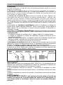
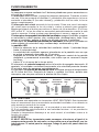
FONCTIONNEMENT
Commandes
La hotte fonctionne à l’aide de cinq (5) boutons-poussoirs situés sur le bord
antérieur de votre hotte.
Le Bouton de la lumière allume et éteint les lampes halogènes. En pressant 1
fois la touche, la lumière s’allume au 1
er
niveau; en pressant 2 fois la touche, la
lumière du 2
ème
niveau s’allume (éclairage plus intense); en pressant encore une
fois la touche, la lumière s’éteint.
Le Bouton de la lumière du verre actionne la lumière du verre. Appuyer sur
l’interrupteur de verre pour allumer la lumière correspondante – appuyer une
seconde fois pour éteindre. Presser sans relâcher le bouton pour activer le
capteur automatique de lumière. Lorsque l’affichage du témoin lumineux indique
“A”, la lumière de verre s’allume automatiquement quand la pièce tombe dans
l’obscurité. Appuyer une seconde fois pour désactiver le capteur et éteindre la
lumière.
L’interrupteur de Ventilateur Arrêt/Régime arrête le ventilateur ou change sa
vitesse selon quatre régimes différents : élevé, moyen-élevé, moyen-faible et
faible régime. Si l’on maintient le bouton enfoncé pendant 2 secondes, le
ventilateur s’arrête.
L’interrupteur de Ventilateur Marche/Régime actionne le ventilateur ou change sa
vitesse selon quatre régimes différents : faible, moyen-faible, moyen-élevé et élevé.
L’Indicateur DEL :
- Il indique la vitesse du ventilateur de 1 (régime faible) à 4 (régime élevé).
- Il indique en clignotant la vitesse du ventilateur lorsque la minuterie de 10
minutes est activée.
- Après 30 heures d’utilisation, le segment central de l’indicateur clignote puis
demeure allumé, indiquant que les filtres doivent être nettoyés.
- Il indique “A” si le capteur de la lumière c’est actionné.
L’Interrupteur de minuterie actionne un dispositif de minuterie qui se trouvait
désactivé. Lorsque l’on appui sur ce bouton, le ventilateur continue à fonctionner
pendant 10 minutes au régime réglé, puis s’arrête automatiquement.
Le bouton de Réamorçage de l’alerte de filtre remet le compteur de 30 heures
à zéro pour les filtres. Après avoir nettoyé ou remplacé les filtres, appuyez une
fois sur ce bouton pour remettre l’alerte à zéro.
HEAT SENTRY
MC
Votre hotte est munie d’un thermostat HEAT SENTRY
MC
. Ce thermostat est un
dispositif qui actionnera ou augmentera la vitesse du ventilateur s’il détecte une
chaleur excessive au-dessus de la surface de cuisson.
1) Si le ventilateur n’est pas en marche - il actionnera le ventilateur en haute
vitesse.
2) Si le ventilateur fonctionne en basse vitesse - le ventilateur tournera en haute
vitesse.
Lorsque la température revient à la normale, le ventilateur retourne à sa vitesse
d’origine.
AVERTISSEMENT
Le thermostat HEAT SENTRY
MC
peu actionner la hotte même si la hotte est
arrêtée. Si tel est le cas, il est impossible de l’arrêter avec l’interrupteur. Si
vous devez arrêter le ventilateur, faites-le à partir du panneau électrique
principal.
Bouton
de la
lumière
Minuterie/
Réamorçage de
l’alerte de filtre
Bouton de la
lumière du verre
Ventilateur
Arrêt/Régime
Ventilateur
Marche/Régime
Indicateur
DEL

- 18 -
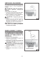
AMPOULES HALOGENES
Ce modèle de hotte veut deux (2) ampoules
halogènes (Type T3, 12Volt, 20 Watt Max, G-
4 Base).
ATTENTION: avant de procéder à
quelconque opération, débranchez
l’appareil.
Pour changer les ampoules:
1. Ouvrez le couvercle en faisant levier grâce
aux fissures prévues à cet effet. Fig. 2.
2. Retirez l’ampoule en tirant latéralement.
(NE LA FAITES PAS TOURNER).
ATTENTION: l’ampoule peut être
chaude!
3. Remplacer par une ampoule ayant les
mêmes caractéristiques (T3, 12Volt, 20
Watt Max, G-4 Base). Ne touchez pas
l’ampoule neuve de vos mains nues.
ATTENTION: L’utilisation d’ampoules
de plus de 20 watts provoquera
l’ouverture du fusible.
FIG. 2
REMPLACEMENT FUSIBLE
SI LES AMPOULES NE FONCTIONNENT
PAS, DÉBRANCHEZ L’ALIMENTATION À
L’ENTRÉE DE SERVICE. CONTRÔLEZ LE
FUSIBLE ET REMPLACEZ-LE SI
NÉCESSAIRE.
1. Enlevez le filtre anti-graisse.
2. Dévissez la protection du support de
fusible et retirez le fusible.
3. Remplacez le fusible par un autre de
même taille et de même intensité (5 x 20
mm, 4 amp, 125 volts).
!
ATTENTION : L’utilisation d’un fusible
de plus de 4 amps peut endommager
le transformateur.
4. Replacez la protection du support de
fusible.
5. Rebranchez l’alimentation à l’entrée de
service.
FUSIBLE
FIG. 3
FILTRE ANTI-GRAISSE

- 19 -
ENTRETIEN
Un bon entretien de votre hotte garantira une excellente performance.
Filtre anti-graisse
Le filtre anti-graisse doit être nettoyé fréquemment. Utilisez une solution contenant
un détergent tiède. Le filtre anti-graisse peut être lavé au lave-vaisselle.
Voir la section “INSTALLER LES FILTRES” pour les instructions relatives au
démontage et à l’installation.
Nettoyage de votre hotte
L’acier inoxydable est une des matières les plus faciles à nettoyer. Un entretien de
temps en temps permettra de le conserver en parfait état. Conseils pour le nettoyage:
● Eau chaude et savon ou détergent est tout ce qui est normalement nécessaire.
● Après chaque nettoyage, rincez bien à l’eau claire. Essuyez avec un chiffon
propre et doux afin d’éviter les taches d’eau.
● Si des décolorations ou des dépôts persistent, utilisez un nettoyant domestique non
abrasif ou de la poudre pour l’acier inoxydable et un peu d’eau et un chiffon doux.
● Dans les cas difficiles, utilisez une éponge en plastique ou une brosse douce
avec du nettoyant et de l’eau. Frottez légèrement en suivant la direction du
polissage ou du “grain” de l’acier inoxydable. Evitez de frotter trop fort afin de ne
pas abîmer la surface.
● NE LAISSEZ PAS les taches trop longtemps.
● N’UTILISEZ PAS de laines d’acier ordinaires ou des brosses en acier. Des débris
d’acier pourraient adhérer à la surface et causer de la rouille.
● NE PERMETTEZ PAS que des solutions salées, des désinfectants, des
blanchissants ou des produits nettoyants restent en contact avec l’acier pendant
longtemps. Beaucoup de ces produits contiennent des produits chimiques qui
pourraient causer des dommages. Rincez à l’eau immédiatement s’ils entrent en
contact et essuyez avec un chiffon humide.
Les surfaces peintes doivent être nettoyées avec de l’eau tiède additionnée d’un
détergent doux seulement.

- 20 -
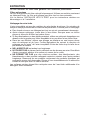
8 VIS D’ASSEMBLAGE
(4.8 x 38mm Tête ronde)
8 CHEVILLES
6 VIS
D’ASSEMBLAGE
(3.9 x 9.5mm
Tête ronde)
2 VIS
D’ASSEMBLAGE
(3.9 x 6mm Tête
plate)
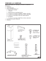
PREPAREZ LA HOTTE
Enlever la hotte dans l’emballage et controller le
contenu.
Vous devez recevoir :
1 - Hotte
1 - Conduit décoratif
1 - Sachet (B080810747) avec:
1 - Étrier d’assemblage
1 - Collier d’évacuation
1 - Étrier de support
8 - Vis d’assemblage (4.8 x 38mm Tête ronde)
6 - Vis d’assemblage (3.9 x 9.5mm Tête ronde)
2 - Vis d’assemblage (3.9 x 6 mm Tête plate)
8 - Chevilles
1 - Vis d’assemblage (2.9 x 9.5mm Tête ronde)
1 - Instructions pour l’installation
1 - Garantie
ETRIER
D’ASSEMBLAGE
COLLIER
D’EVACUATION
ETRIER DE SUPPORT
CONDUIT
DECORATIF
1 VIS
D’ASSEMBLAGE
(2.9 x 9.5mm
Tête ronde)
FIG. 4
La page est en cours de chargement...
La page est en cours de chargement...
La page est en cours de chargement...
La page est en cours de chargement...
La page est en cours de chargement...
La page est en cours de chargement...
La page est en cours de chargement...
La page est en cours de chargement...
La page est en cours de chargement...
La page est en cours de chargement...
La page est en cours de chargement...
La page est en cours de chargement...
La page est en cours de chargement...
La page est en cours de chargement...
La page est en cours de chargement...
La page est en cours de chargement...
La page est en cours de chargement...
La page est en cours de chargement...
La page est en cours de chargement...
La page est en cours de chargement...
La page est en cours de chargement...
La page est en cours de chargement...
La page est en cours de chargement...
La page est en cours de chargement...
-
 1
1
-
 2
2
-
 3
3
-
 4
4
-
 5
5
-
 6
6
-
 7
7
-
 8
8
-
 9
9
-
 10
10
-
 11
11
-
 12
12
-
 13
13
-
 14
14
-
 15
15
-
 16
16
-
 17
17
-
 18
18
-
 19
19
-
 20
20
-
 21
21
-
 22
22
-
 23
23
-
 24
24
-
 25
25
-
 26
26
-
 27
27
-
 28
28
-
 29
29
-
 30
30
-
 31
31
-
 32
32
-
 33
33
-
 34
34
-
 35
35
-
 36
36
-
 37
37
-
 38
38
-
 39
39
-
 40
40
-
 41
41
-
 42
42
-
 43
43
-
 44
44


Best Blower WC26E Manuel utilisateur
- Catégorie
- Hottes
- Taper
- Manuel utilisateur
dans d''autres langues
- English: Best Blower WC26E User manual
- español: Best Blower WC26E Manual de usuario