Miller MC000000 Le manuel du propriétaire
- Catégorie
- Système de soudage
- Taper
- Le manuel du propriétaire
Ce manuel convient également à

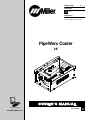
PipeWorx Cooler
CE
Processes
Description
Cooler For Water-Cooled Torches
Cooler
OM-255 999A 2011−12
File: Cooler
Visit our website at
www.MillerWelds.com

Miller Electric manufactures a full line
of welders and welding related equipment.
For information on other quality Miller
products, contact your local Miller distributor to receive the latest full
line catalog or individual specification sheets. To locate your nearest
distributor or service agency call 1-800-4-A-Miller, or visit us at
www.MillerWelds.com on the web.
Thank you and congratulations on choosing Miller. Now you can get
the job done and get it done right. We know you don’t have time to do
it any other way.
That’s why when Niels Miller first started building arc welders in 1929,
he made sure his products offered long-lasting value and superior
quality. Like you, his customers couldn’t afford anything less. Miller
products had to be more than the best they could be. They had to be the
best you could buy.
Today, the people that build and sell Miller products continue the
tradition. They’re just as committed to providing equipment and service
that meets the high standards of quality and value established in 1929.
This Owner’s Manual is designed to help you get the most out of your
Miller products. Please take time to read the Safety precautions. They
will help you protect yourself against potential hazards on the worksite.
We’ve made installation and operation quick
and easy. With Miller you can count on years
of reliable service with proper maintenance.
And if for some reason the unit needs repair,
there’s a Troubleshooting section that will
help you figure out what the problem is. The
parts list will then help you to decide the
exact part you may need to fix the problem.
Warranty and service information for your
particular model are also provided.
Miller is the first welding
equipment manufacturer in
the U.S.A. to be registered to
the ISO 9001 Quality System
Standard.
Working as hard as you do
− every power source from
Miller is backed by the most
hassle-free warranty in the
business.
From Miller to You
Mil_Thank 2009−09

TABLE OF CONTENTS
SECTION 1 − SAFETY PRECAUTIONS - READ BEFORE USING 1...................................
1-1. Symbol Usage 1........................................................................
1-2. Cooling Equipment Hazards 1............................................................
1-3. Additional Symbols For Installation, Operation, And Maintenance 1.............................
1-4. California Proposition 65 Warnings 2.......................................................
1-5. Principal Safety Standards 2.............................................................
1-6. EMF Information 2......................................................................
SECTION 2 − CONSIGNES DE SÉCURITÉ − LIRE AVANT UTILISATION 3............................
2-1. Symboles utilisés 3.....................................................................
2-2. Dangers liés aux équipements de refroidissement 3..........................................
2-3. Dangers supplémentaires en relation avec l’installation, le fonctionnement et la maintenance 3......
2-4. Proposition californienne 65 Avertissements 4...............................................
2-5. Principales normes de sécurité 4..........................................................
2-6. Informations relatives aux CEM 4.........................................................
SECTION 3 − DEFINITIONS 5...................................................................
3-1. Warning Label Definitions For CE Products 5................................................
3-2. WEEE Label (For Products Sold Within The EU) 6...........................................
3-3. Symbols And Definitions 6...............................................................
SECTION 4 − SPECIFICATIONS 7................................................................
4-1. Important Information Regarding CE Products (Sold Within The EU) 7...........................
4-2. Serial Number And Rating Label Location 7.................................................
4-3. Specifications 7........................................................................
4-4. Coolant Chart 7........................................................................
SECTION 5 − INSTALLATION 8..................................................................
5-1. Installing Optional Handles, Running Gear And Cooler 8......................................
SECTION 6 − OPERATION 9....................................................................
6-1. Control Panel 9.........................................................................
SECTION 7 − MAINTENANCE 10.................................................................
7-1. Routine Maintenance 10..................................................................
7-2. Coolant Maintenance 11..................................................................
7-3. Flow Direction 12........................................................................
7-4. Troubleshooting 12......................................................................
SECTION 8 − ELECTRICAL DIAGRAM 13..........................................................
SECTION 9 − PARTS LIST 14.....................................................................
WARRANTY

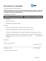
DECLARATION OF CONFORMITY
for European Community (CE marked) products.
ITW Welding Products Italy S.r.l Via Privata Iseo 6/E, 20098 San Giuliano M.se, (MI) Italy declares that
the product(s) identified in this declaration conform to the essential requirements and provisions of
the stated Council Directive(s) and Standard(s).
Product/Apparatus Identification:
Product Stock Number
PIPEWORX COOLER 028042102
Council Directives:
2006/95/EC Low Voltage
2004/108/EC Electromagnetic Compatibility
Standards:
IEC 609741 Arc Welding Equipment Welding Power Sources: edition 3, 200507.
IEC 609742 Arc Welding Equipment – Liquid Cooling Systems: edition 2.0, 200711.
IEC 6097410 Arc Welding Equipment Electromagnetic Compatibility Requirements: edition 2.0, 200708.
EN 50445:2008 Product family standard to demonstrate compliance of equipment for resistance welding, arc
welding and allied processes with the basic restrictions related to human exposure to electromagnetic fields
(0Hz300Hz)
EU Signatory:
November 18
th
, 2011
___________________________________________________________________________________
Massimigliano Lavarini Date of Declaration
ELECTRONIC ENGINEER R&D TECH. SUPPORT
956 142 920

OM-255 999 Page 1
SECTION 1 − SAFETY PRECAUTIONS - READ BEFORE USING
coolers 2011−10
7
Protect yourself and others from injury — read, follow, and save these important safety precautions and operating instructions.
1-1. Symbol Usage
DANGER! − Indicates a hazardous situation which, if
not avoided, will result in death or serious injury. The
possible hazards are shown in the adjoining symbols
or explained in the text.
Indicates a hazardous situation which, if not avoided,
could result in death or serious injury. The possible
hazards are shown in the adjoining symbols or ex-
plained in the text.
NOTICE − Indicates statements not related to personal injury.
. Indicates special instructions.
This group of symbols means Warning! Watch Out! ELECTRIC
SHOCK, MOVING PARTS, and HOT PARTS hazards. Consult sym-
bols and related instructions below for necessary actions to avoid the
hazards.
1-2. Cooling Equipment Hazards
The symbols shown below are used throughout this manual
to call attention to and identify possible hazards. When you
see the symbol, watch out, and follow the related instructions
to avoid the hazard. The safety information given below is
only a summary of the more complete safety information
found in the Safety Standards listed in Section 1-5. Read and
follow all Safety Standards.
Only qualified persons should install, operate, maintain, and
repair this unit.
During operation, keep everybody, especially children, away.
ELECTRIC SHOCK can kill.
Touching live electrical parts can cause fatal shocks
or severe burns. The input power circuit and machine
internal circuits are also live when power is on.
Incorrectly installed or improperly grounded equip-
ment is a hazard.
D Do not touch live electrical parts.
D Disconnect input power or stop engine before installing or
servicing this equipment. Lockout/tagout input power according to
OSHA 29 CFR 1910.147 (see Safety Standards).
D Properly install, ground, and operate this equipment according to
its Owner’s Manual and national, state, and local codes.
D Always verify the supply ground − check and be sure that input
power cord ground wire is properly connected to ground terminal in
disconnect box or that cord plug is connected to a properly
grounded receptacle outlet.
D Keep cords dry, free of oil and grease, and protected from hot metal
and sparks.
D Frequently inspect input power cord for damage or bare wiring −
replace cord immediately if damaged − bare wiring can kill.
D Turn off all equipment when not in use.
D Use only well-maintained equipment. Repair or replace damaged
parts at once. Maintain unit according to manual.
D Keep all panels and covers securely in place.
HOT PARTS can burn.
D Do not touch hot parts bare handed.
D Allow cooling period before working on equip-
ment.
D To handle hot parts, use proper tools and/or
wear heavy, insulated welding gloves and
clothing to prevent burns.
FLYING METAL or DIRT can injure eyes.
D Wear approved safety glasses with side
shields even under your welding helmet.
1-3. Additional Symbols For Installation, Operation, And Maintenance
FALLING EQUIPMENT can injure.
D Use equipment of adequate capacity to lift and
support unit.
D If using lift forks to move unit, be sure forks are
long enough to extend beyond opposite side of
unit.
D Keep equipment (cables and cords) away from moving vehicles
when working from an aerial location.
D Follow the guidelines in the Applications Manual for the Revised
NIOSH Lifting Equation (Publication No. 94−110) when manu-
ally lifting heavy parts or equipment.
OVERUSE can cause OVERHEATING
D Allow cooling period; follow rated duty cycle.
D Do not block or filter airflow to unit.
MOVING PARTS can injure.
D Keep away from moving parts such as fans.
D Keep all doors, panels, covers, and guards
closed and securely in place.
D Have only qualified persons remove doors, panels, covers, or
guards for maintenance and troubleshooting as necessary.
D Reinstall doors, panels, covers, or guards when maintenance is
finished and before reconnecting input power.
READ INSTRUCTIONS.
D Read and follow all labels and the Owner’s
Manual carefully before installing, operating, or
servicing unit. Read the safety information at
the beginning of the manual and in each
section.
D Use only genuine replacement parts from the manufacturer.
D Perform maintenance and service according to the Owner’s
Manuals, industry standards, and national, state, and local
codes.

OM-255 999 Page 2
1-4. California Proposition 65 Warnings
Welding or cutting equipment produces fumes or gases
which contain chemicals known to the State of California to
cause birth defects and, in some cases, cancer. (California
Health & Safety Code Section 25249.5 et seq.)
This product contains or produces a chemical known to the
state of California to cause cancer or birth defects (or other
reproductive harm). (California Health & Safety Code Section
25249.5 et seq.)
This product contains chemicals, including lead, known to
the state of California to cause cancer, birth defects, or other
reproductive harm. Wash hands after use.
1-5. Principal Safety Standards
Safety in Welding, Cutting, and Allied Processes, ANSI Standard Z49.1,
is available as a free download from the American Welding Society at
http://www.aws.org or purchased from Global Engineering Documents
(phone: 1-877-413-5184, website: www.global.ihs.com).
Safe Practices for the Preparation of Containers and Piping for Welding
and Cutting, American Welding Society Standard AWS F4.1, from Glob-
al Engineering Documents (phone: 1-877-413-5184, website:
www.global.ihs.com).
Safe Practices for Welding and Cutting Containers that have Held Com-
bustibles, American Welding Society Standard AWS A6.0, from Global
Engineering Documents (phone: 1-877-413-5184,
website: www.global.ihs.com).
National Electrical Code, NFPA Standard 70, from National Fire Protec-
tion Association, Quincy, MA 02269 (phone: 1-800-344-3555, website:
www.nfpa.org and www. sparky.org).
Safe Handling of Compressed Gases in Cylinders, CGA Pamphlet P-1,
from Compressed Gas Association, 14501 George Carter Way, Suite
103, Chantilly, VA 20151 (phone: 703-788-2700, website:
www.cganet.com).
Safety in Welding, Cutting, and Allied Processes, CSA Standard
W117.2, from Canadian Standards Association, Standards Sales, 5060
Spectrum Way, Suite 100, Ontario, Canada L4W 5NS (phone:
800-463-6727, website: www.csa-international.org).
Safe Practice For Occupational And Educational Eye And Face Protec-
tion, ANSI Standard Z87.1, from American National Standards Institute,
25 West 43rd Street, New York, NY 10036 (phone: 212-642-4900, web-
site: www.ansi.org).
Standard for Fire Prevention During Welding, Cutting, and Other Hot
Work, NFPA Standard 51B, from National Fire Protection Association,
Quincy, MA 02269 (phone: 1-800-344-3555, website: www.nfpa.org.
OSHA, Occupational Safety and Health Standards for General Indus-
try, Title 29, Code of Federal Regulations (CFR), Part 1910, Subpart Q,
and Part 1926, Subpart J, from U.S. Government Printing Office, Super-
intendent of Documents, P.O. Box 371954, Pittsburgh, PA 15250-7954
(phone: 1-866-512-1800) (there are 10 OSHA Regional Offices—
phone for Region 5, Chicago, is 312-353-2220, website:
www.osha.gov).
Applications Manual for the Revised NIOSH Lifting Equation, The Na-
tional Institute for Occupational Safety and Health (NIOSH), 1600
Clifton Rd, Atlanta, GA 30333 (phone: 1-800-232-4636, website:
www.cdc.gov/NIOSH).
1-6. EMF Information
Electric current flowing through any conductor causes localized electric
and magnetic fields (EMF). Welding current creates an EMF field
around the welding circuit and welding equipment. EMF fields may inter-
fere with some medical implants, e.g. pacemakers. Protective
measures for persons wearing medical implants have to be taken. For
example, restrict access for passers−by or conduct individual risk as-
sessment for welders. All welders should use the following procedures
in order to minimize exposure to EMF fields from the welding circuit:
1. Keep cables close together by twisting or taping them, or using a
cable cover.
2. Do not place your body between welding cables. Arrange cables
to one side and away from the operator.
3. Do not coil or drape cables around your body.
4. Keep head and trunk as far away from the equipment in the
welding circuit as possible.
5. Connect work clamp to workpiece as close to the weld as
possible.
6. Do not work next to, sit or lean on the welding power source.
7. Do not weld whilst carrying the welding power source or wire
feeder.
About Implanted Medical Devices:
Implanted Medical Device wearers should consult their doctor and the
device manufacturer before performing or going near arc welding, spot
welding, gouging, plasma arc cutting, or induction heating operations.
If cleared by your doctor, then following the above procedures is recom-
mended.

OM-255 999 Page 3
SECTION 2 − CONSIGNES DE SÉCURITÉ − LIRE AVANT UTILISATION
Cooler 2011−03fre
Pour écarter les risques de blessure pour vous−même et pour autrui — lire, appliquer et ranger en lieu sûr ces consignes relatives
aux précautions de sécurité et au mode opératoire.
2-1. Symboles utilisés
DANGER! − Indique une situation dangereuse qui si on
l’évite pas peut donner la mort ou des blessures graves.
Les dangers possibles sont montrés par les symboles
joints ou sont expliqués dans le texte.
Indique une situation dangereuse qui si on l’évite pas
peut donner la mort ou des blessures graves. Les dan-
gers possibles sont montrés par les symboles joints ou
sont expliqués dans le texte.
NOTE − Indique des déclarations pas en relation avec des blessures
personnelles.
. Indique des instructions spécifiques.
Ce groupe de symboles veut dire Avertissement! Attention! DANGER
DE CHOC ELECTRIQUE, PIECES EN MOUVEMENT, et PIECES
CHAUDES. Consulter les symboles et les instructions ci-dessous y
afférant pour les actions nécessaires afin d’éviter le danger.
2-2. Dangers liés aux équipements de refroidissement
Les symboles représentés ci-dessous sont utilisés dans ce ma-
nuel pour attirer l’attention et identifier les dangers possibles. En
présence de l’un de ces symboles, prendre garde et suivre les
instructions afférentes pour éviter tout risque. Les instructions
en matière de sécurité indiquées ci-dessous ne constituent
qu’un sommaire des instructions de sécurité plus complètes
fournies dans les normes de sécurité énumérées dans la Sec-
tion 2-5. Lire et observer toutes les normes de sécurité.
Seul un personnel qualifié est autorisé à installer, faire fonc-
tionner, entretenir et réparer cet appareil.
Pendant le fonctionnement, maintenir à distance toutes les
personnes, notamment les enfants de l’appareil.
UNE DÉCHARGE ÉLECTRIQUE peut
entraîner la mort.
Le contact d’organes électriques sous tension peut
provoquer des accidents mortels ou des brûlures
graves. Le circuit d’alimentation et les circuits
internes de la machine sont également sous tension
lorsque l’alimentation est sur Marche. Un équipement installé ou mis
à la terre de manière incorrecte ou impropre constitue un danger.
D Ne pas toucher aux pièces électriques sous tension.
D Couper l’alimentation ou arrêter le moteur avant de procéder à l’in-
stallation, à la réparation ou à l’entretien de l’appareil. Déverrouiller
l’alimentation selon la norme OSHA 29 CFR 1910.147 (voir nor-
mes de sécurité).
D Installez, mettez à la terre et utilisez correctement cet équipement
conformément à son Manuel d’Utilisation et aux réglementations
nationales, gouvernementales et locales.
D Toujours vérifier la terre du cordon d’alimentation. Vérifier et
s’assurer que le fil de terre du cordon d’alimentation est bien
raccordé à la borne de terre du sectionneur ou que la fiche du
cordon est raccordée à une prise correctement mise à la terre.
D Les câbles doivent être exempts d’humidité, d’huile et de graisse;
protégez−les contre les étincelles et les pièces métalliques
chaudes.
D Vérifier fréquemment le cordon d’alimentation afin de s’assurer
qu’il n’est pas altéré ou à nu, le remplacer immédiatement s’il l’est.
Un fil à nu peut entraîner la mort.
D L’équipement doit être hors tension lorsqu’il n’est pas utilisé.
D N’utiliser qu’un matériel en bon état. Réparer ou remplacer sur-le-
champ les pièces endommagées. Entretenir l’appareil conformé-
ment à ce manuel.
D S’assurer que tous les panneaux et couvercles sont correctement
en place.
LES PIÈCES CHAUDES peuvent
provoquer des brûlures.
D Ne pas toucher à mains nues les partie
s
chaudes.
D Prévoir une période de refroidissement avant d
e
travailler à l’équipement.
D Ne pas toucher aux pièces chaudes, utiliser les outils recomman
-
dés et porter des gants de soudage et des vêtements épais pou
r
éviter les brûlures.
DES PIECES DE METAL ou DES
SALETES peuvent provoquer des
blessures dans les yeux.
D Porter des lunettes de sécurité avec écrans la-
téraux ou un écran facial.
2-3. Dangers supplémentaires en relation avec l’installation, le fonctionnement et la maintenance
LA CHUTE DE L’ÉQUIPEMENT peut
provoquer des blessures.
D Utiliser un équipement de levage de capacité
suffisante pour lever l’appareil.
D En utilisant des fourches de levage pour dépla-
cer l’unité, s’assurer que les fourches sont
suffisamment longues pour dépasser du côté
opposé de l’appareil.
D Tenir l’équipement (câbles et cordons) à distance des véhicules
mobiles lors de toute opération en hauteur.
D Suivre les consignes du Manuel des applications pour l’équation
de levage NIOSH révisée (Publication Nº94–110) lors du levage
manuelle de pièces ou équipements lourds.
L’EMPLOI EXCESSIF peut
SURCHAUFFER L’ÉQUIPEMENT.
D Prévoir une période de refroidissement ; res-
pecter le cycle opératoire nominal.
D Ne pas obstruer les passages d’air du poste.

OM-255 999 Page 4
Les PIÈCES MOBILES peuvent
causer des blessures.
D S’abstenir de toucher des organes mobiles tels
que des ventilateurs.
D Maintenir fermés et verrouillés les portes,
panneaux, recouvrements et dispositifs de
protection.
D Lorsque cela est nécessaire pour des travaux d’entretien et de
dépannage, faire retirer les portes, panneaux, recouvrements
ou dispositifs de protection uniquement par du personnel qua-
lifié.
D Remettre les portes, panneaux, recouvrements ou dispositifs de
protection quand l’entretien est terminé et avant de rebrancher
l’alimentation électrique.
LIRE LES INSTRUCTIONS.
D Lire et appliquer les instructions sur les
étiquettes et le Mode d’emploi avant l’instal-
lation, l’utilisation ou l’entretien de l’appareil.
Lire les informations de sécurité au début du
manuel et dans chaque section.
D N’utiliser que les pièces de rechange recommandées par le
constructeur.
2-4. Proposition californienne 65 Avertissements
Les équipements de soudage et de coupage produisent des
fumées et des gaz qui contiennent des produits chimiques
dont l’État de Californie reconnaît qu’ils provoquent des mal-
formations congénitales et, dans certains cas, des cancers.
(Code de santé et de sécurité de Californie, chapitre 25249.5
et suivants)
Ce produit contient ou forme un produit chimique reconnu
par l’état de Californie de provoquer le cancer ou malfor-
mations de naissance (ou autre problèmes reproductifs.
(Code de santé et de sécurité de Californie, chapitre 25249.5
et suivants).
Ce produit contient des produits chimiques, notamment du
plomb, dont l’État de Californie reconnaît qu’ils provoquent
des cancers, des malformations congénitales ou d’autres
problèmes de procréation. Se laver les mains après
utilisation.
2-5. Principales normes de sécurité
Safety in Welding, Cutting, and Allied Processes, ANSI Standard Z49.1,
is available as a free download from the American Welding Society at
http://www.aws.org or purchased from Global Engineering Documents
(phone: 1-877-413-5184, website: www.global.ihs.com).
Safe Practices for the Preparation of Containers and Piping for Welding
and Cutting, American Welding Society Standard AWS F4.1, from Glob-
al Engineering Documents (phone: 1-877-413-5184, website:
www.global.ihs.com).
Safe Practices for Welding and Cutting Containers that have Held Com-
bustibles, American Welding Society Standard AWS A6.0, from Global
Engineering Documents (phone: 1-877-413-5184,
website: www.global.ihs.com).
National Electrical Code, NFPA Standard 70, from National Fire Protec-
tion Association, Quincy, MA 02269 (phone: 1-800-344-3555, website:
www.nfpa.org and www. sparky.org).
Safe Handling of Compressed Gases in Cylinders, CGA Pamphlet P-1,
from Compressed Gas Association, 14501 George Carter Way, Suite
103, Chantilly, VA 20151 (phone: 703-788-2700, website:
www.cganet.com).
Safety in Welding, Cutting, and Allied Processes, CSA Standard
W117.2, from Canadian Standards Association, Standards Sales, 5060
Spectrum Way, Suite 100, Ontario, Canada L4W 5NS (phone:
800-463-6727, website: www.csa-international.org).
Safe Practice For Occupational And Educational Eye And Face Protec-
tion, ANSI Standard Z87.1, from American National Standards Institute,
25 West 43rd Street, New York, NY 10036 (phone: 212-642-4900, web-
site: www.ansi.org).
Standard for Fire Prevention During Welding, Cutting, and Other Hot
Work, NFPA Standard 51B, from National Fire Protection Association,
Quincy, MA 02269 (phone: 1-800-344-3555, website: www.nfpa.org.
OSHA, Occupational Safety and Health Standards for General Indus-
try, Title 29, Code of Federal Regulations (CFR), Part 1910, Subpart Q,
and Part 1926, Subpart J, from U.S. Government Printing Office, Super-
intendent of Documents, P.O. Box 371954, Pittsburgh, PA 15250-7954
(phone: 1-866-512-1800) (there are 10 OSHA Regional Offices—
phone for Region 5, Chicago, is 312-353-2220, website:
www.osha.gov).
Applications Manual for the Revised NIOSH Lifting Equation, The Na-
tional Institute for Occupational Safety and Health (NIOSH), 1600
Clifton Rd, Atlanta, GA 30333 (phone: 1-800-232-4636, website:
www.cdc.gov/NIOSH).
2-6. Informations relatives aux CEM
Le courant électrique qui traverse tout conducteur génère des champs
électromagnétiques (CEM) à certains endroits. Le courant de soudage
crée un CEM autour du circuit et du matériel de soudage. Les CEM
peuvent créer des interférences avec certains implants médicaux
comme des stimulateurs cardiaques. Des mesures de protection pour
les porteurs d’implants médicaux doivent être prises: Limiter par
exemple tout accès aux passants ou procéder à une évaluation des
risques individuels pour les soudeurs. Tous les soudeurs doivent
appliquer les procédures suivantes pour minimiser l’exposition aux
CEM provenant du circuit de soudage:
1. Rassembler les câbles en les torsadant ou en les attachant avec
du ruban adhésif ou avec une housse.
2. Ne pas se tenir au milieu des câbles de soudage. Disposer les
câbles d’un côté et à distance de l’opérateur.
3. Ne pas courber et ne pas entourer les câbles autour de votre
corps.
4. Maintenir la tête et le torse aussi loin que possible du matériel du
circuit de soudage.
5. Connecter la pince sur la pièce aussi près que possible de la
soudure.
6. Ne pas travailler à proximité d’une source de soudage, ni
s’asseoir ou se pencher dessus.
7. Ne pas souder tout en portant la source de soudage ou le
dévidoir.
En ce qui concerne les implants médicaux :
Les porteurs d’implants doivent d’abord consulter leur médecin avant
de s’approcher des opérations de soudage à l’arc, de soudage par
points, de gougeage, du coupage plasma ou de chauffage par induc-
tion. Si le médecin approuve, il est recommandé de suivre les
procédures précédentes.

OM-255 999 Page 5
SECTION 3 − DEFINITIONS
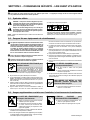
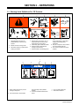
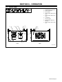
3-1. Warning Label Definitions For CE Products
S-180 663
1 2 3 4 5
6
7 8 9
1 Warning! Watch Out! There are
possible hazards as shown by the
symbols.
2 Electric shock from wiring can kill.
3 Disconnect input plug or power before
working on machine.
4 Moving parts, such as fans, can cut
fingers and hands and cause injury.
Keep away from moving parts.
5 Wear safety glasses with side shields.
6 Read the Owner’s Manual before
working on this machine.
7 Read the labels on the welding power
source, wire feeder, or other major
equipment for welding safety
information.
8 Recycle or dispose of used coolant in
an environmentally safe way.
9 Do not remove or paint over (cover)
the label.
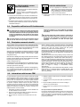
1 Notice: follow instructions to prevent
damage to equipment.
2 Use manufacturer’s recommended
low conductivity coolant (Part No.
043810).
3 Do not use untreated water that can
freeze.
4 Do not overfill coolant tank.
5 Read Owner’s Manual.
23 45
1

OM-255 999 Page 6
1
2
1 Warning! Watch Out! There
are possible hazards as
shown by the symbols.
2 Moving parts, such as fans,
can cut fingers and hands and
cause injury. Keep away from
moving parts.
956.142.629-A
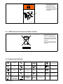
3-2. WEEE Label (For Products Sold Within The EU)
Do not discard this product (where
applicable) with general waste.
Reuse or recycle Waste Electrical
and Electronic Equipment (WEEE)
by disposing at a designated collec-
tion facility.
Contact your local recycling office
or your local distributor for further
information.
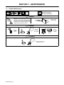
3-3. Symbols And Definitions
A
Amperes Alternating Current Voltage Input
Circulating Unit
With Coolant Pump
V
Volts
Water (Coolant)
Input
Water (Coolant)
Output
Line Connection
Protective Earth
(Ground)
IP
Degree Of
Protection
I
1
Primary Current
Hz
Hertz
On Off
U
1
Primary Voltage Single Phase
Gas Tungsten Arc
Welding (GTAW) /
Tungsten Inert Gas
(TIG) Welding
Gas Metal Arc
Welding MIG/MAG
(GMAW)
Circuit Breaker

OM-255 999 Page 7
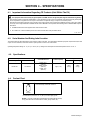
SECTION 4 − SPECIFICATIONS
4-1. Important Information Regarding CE Products (Sold Within The EU)
! This equipment shall not be used by the general public as the EMF limits for the general public might be exceeded during welding.
This equipment is built in accordance with EN 60974−1 and is intended to be used only in an occupational environment (where the general public
access is prohibited or regulated in such a way as to be similar to occupational use) by an expert or an instructed person.
Wire feeders and ancillary equipment (such as torches, liquid cooling systems and arc striking and stabilizing devices) as part of the welding
circuit may not be a major contributor to the EMF. See the Owner’s Manuals for all components of the welding circuit for additional EMF exposure
information.
S The EMF assessment on this equipment was conducted at 0.5 meter.
S At a distance of 1 meter the EMF exposure values were less than 20% of the permissible values.
ce-emf 1 2010-10
4-2. Serial Number And Rating Label Location
The serial number and rating information for this product is located on the front . Use rating label to determine input power requirements and/or rated
output. For future reference, write serial number in space provided on back cover of this manual.
Operating Temperature Range: 14° F (-10° C) to 104° F (40° C). Ratings were developed at an ambient temperature of 20° C to 25° C.
4-3. Specifications
Input Power
Overall Dimensions Coolant Capacity
Weight
Pump Blower Net Wet Weight
115 Volts AC 115 Volts AC
Length: 30 in.
(762 mm)
Width: 19-3/8 in.
(492 mm)
Height: 12 in.
(305 mm)
3 gal (11.4 L)
101 lb
(46 kg)
126 lb
(57 kg)
4-4. Coolant Chart
Low Conductivity Coolant No. 043 810*
*Coolant 043 810 protects to -37° F (-38°C) and resist algae growth.
Coolant
NOTICE − Use of any coolant other than that listed in the table voids the warranty
on any parts that come in contact with the coolant (pump, radiator, etc.).

OM-255 999 Page 8
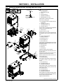
SECTION 5 − INSTALLATION
5-1. Installing Optional Handles, Running Gear And Cooler
Ref. 805 302-A / 956142903_2-A / 805 292-A
! Turn Off welding power source, discon-
nect input power.
1 Running Gear 234 359
2 Cooler
3 Wheel 163 463 (2)
4 Flat Washer 602 250 (4)
5 Retaining Ring 121 614 (2)
Install wheels on cylinder tray as shown.
Set cooler on running gear.
. If not installing a cooler, set power source on
running gear.
6 Flat Washer 602 240 (4)
7 Lock Washer 602 211 (4)
8 Screw 601 944 (4)
Secure cooler to running gear using supplied flat
washers, lock washers and screws.
9 Power Source
Set power source on cooler.
Secure power source to cooler using same hard-
ware that was used to secure cooler to running
gear.
10 Cylinder Support Bracket
11 Bushing 170 647 (2)
12 Bushing 004 214 (1)
13 Screw 128 237 (4)
14 Chain 188 441 (2)
Install cylinder support bracket to rear of power
source and secure with supplied screws. Install
bushings and chains.
15 Handle Bracket
16 Handle (2)
17 Tube Cap (4)
Install tube caps into ends of handles.
Remove 5 screws above louvered panel on front
of power source.
Attach handle bracket to front of power source
using the 5 screws previously removed.
Remove 2 screws on the side of the cover on
front of power source.
18 Screw 234 483 (2)
Start supplied upper handle mounting screws in-
to handles by hand on each side of power
source.
19 Screw 604 535 (2)
20 Lock Washer 602 211 (2)
21 Flat Washer 602 240 (2)
Start supplied screws, lock washers and flat
washers into handle bracket by hand on each
side of power source.
22 Screw 604 535 (4)
23 Lock Washer 602 211 (4)
24 Flat Washer 602 240 (4)
Start supplied lower handle mounting screws,
lock washers and flat washers into handles by
hand on each side of power source.
Tighten all handle hardware.
Tools Needed:
1/2 in.
5/16 in.
2
6
7
8
9
1
2
3
4
15
16
5
6
7
8
13
18
19
20
21
22
23
24
17
10
9
11
12
11
14

OM-255 999 Page 9
SECTION 6 − OPERATION
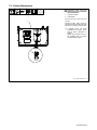
6-1. Control Panel
1 Supplementary Protector CB1
2 Power On/Off Light
3 Flow Indicator
4 Quick Connect; Water Out TIG
Torch
5 Quick Connect; Water In TIG
Torch
6 Coolant Filter
7 Tank Filler Neck
8 Quick Connect; Water Out
MIG Gun
9 Quick Connect; Water In MIG
Gun
Ref. 254 086-A
1
2
3
4
5
6
7
8
9
Front
Back

OM-255 999 Page 10
SECTION 7 − MAINTENANCE
7-1. Routine Maintenance
! Disconnect power
before maintaining.
3 Months
Blow Out Heat
Exchanger Fins
NOTICE − Clean coolant strainer. Severe con-
ditions may require more frequent cleaning
(continuous use, high/low temperatures, dirty
environment, etc.). Failure to properly clean
coolant strainer voids pump warranty.
6 Months
Replace
Cracked
Hoses
Replace
Unreadable
Labels
Change
Coolant (If
Using Water)
12 Months
Change Coolant (If Using
043 810 Coolant)

OM-255 999 Page 11
7-2. Coolant Maintenance
Ref. 254 086-A / Ref. 801 194
! Disconnect cooler plug from
welding power source receptacle
before maintaining.
1 Cooler Front Panel
2 Coolant Filter
Unscrew housing to clean filter and
housing.
Changing coolant: Drain coolant by
tipping unit forward. Fill with clean water
and run for 10 minutes. Drain and refill.
. If replacing hoses, use hoses
compatible with ethylene glycol,
such as Buna-n, Neoprene, or
Hypalon.
NOTE: Oxy-acetylene hoses are
not compatible with any product
containing ethylene glycol.
2
1

OM-255 999 Page 12
7-3. Flow Direction
956142903_1-A
7-4. Troubleshooting
Trouble Remedy
Coolant system does not work. Be sure cooler input power and communication cables from power source are connected to cooler
receptacles.
Check input power line fuses or circuit breaker, and replace or reset if necessary.
Have Factory Authorized Service Agent check motor.
Decreased or no coolant flow. Add coolant.
Check for clogged hoses or coolant filter. Clean filter or clean / replace hoses if necessary.
Disconnect pump, and check for sheared coupling. Replace coupling if necessary.

OM-255 999 Page 13
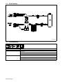
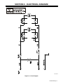
SECTION 8 − ELECTRICAL DIAGRAM
956142907-A
Figure 8-1. Circuit Diagram

OM-255 999 Page 14
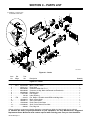
SECTION 9 − PARTS LIST
956142903-F
. Hardware is common and
not available unless listed.
1
5
6
8
9
10
11
12
15
16
17
21
23
24
14
18
22
7
19
20
28
29
19
20
25
27
26
13
4
2
3
30
Figure 9-1. Cooler
Description
Part
No.
Dia.
Mkgs.
Item
No.
Figure 9-1. Cooler
Quantity
1 MOT 057010059 Motor, 170W,115VAC 1... ... . ...............................................
2 V57011071 Pump Assy 1... ......... . .......................................................
3 556049386 Connector, Male 3/8 D .10 3... ......... . ..........................................
4 556049399 Connector, 3 Way, Male 3/8 Female 3/8 Female 3/8 1... ......... . ....................
5 056082099 Radiator Assy 1... ......... . .....................................................
6 116117082 Fan Support 1... .......... . ......................................................
7 176106 Label, Warning 1... ............. . ....................................................
8 FM 213072 Fan, Muffin 115V 60Hz 3400 RPM 6.378 Mtg Holes 1... ... ..... . ....................
9 156006073 Base, w/Pem Studs 1... ......... . ................................................
10 156005171 Side, Cooler Base 2... ......... . .................................................
11 156118083 Panel, Rear Cooler Base 1... ......... . ...........................................
12 +116039032 Shell, Cooler Base w/Pem Nuts 1... ........ . ......................................
13 229325 Foot, Mtg Unit 4... ............. . .....................................................
+When ordering a component originally displaying a precautionary label, the label should also be ordered.
To maintain the factory original performance of your equipment, use only Manufacturer’s Suggested
Replacement Parts. Model and serial number required when ordering parts from your local distributor.

OM-255 999 Page 15
Description
Part
No.
Dia.
Mkgs.
Item
No.
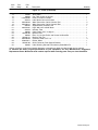
Figure 9-1. Cooler (Continued)
Quantity
14 173955 Tank, Water 1... ............. . .......................................................
15 166608 Cap, Tank Screw−On w/Vent 1... ............. . ........................................
16 +156118082 Panel, Front w/Pem Studs 1... ........ . ..........................................
17 254518 Label, Notice Incorrect Coolant 1... ............. . ......................................
18 556049409 Water Connection, Quick Connect, Red 2... ......... . ...............................
19 556049410 Water Connection, Quick Connect, Blue 2... ......... . ..............................
20 083432 Supplementary Protector 10A 1... ............. . .......................................
21 056072081 Light, Wht Lens 125VAC Neon 1... ......... . ......................................
22 215279 Indicator, Flow 1... ............. . .....................................................
23 188082 Cable, Power 2 ft 7 in 16ga 3c 1... ............. . .......................................
24 156005169 Bracket, Filter 1... ......... . .....................................................
25 166564 Filter, In−Line Low Profile 100 Screen 3/8 Hose Bar 1... ............. . ....................
26 156005170 Bracket, Tank Top 1... ......... . ..................................................
27 556049408 Connector, Male 1/4 D .10 3... ......... . ..........................................
28 556049411 Divider, Water 1... ......... . .....................................................
29 156005168 Quick Connector, Rear Support Bracket 1... ......... . ..............................
30 180663 Label, Warning General Precautionary Static&Wire Fe 1... ............. . ..................
+When ordering a component originally displaying a precautionary label, the label should also be ordered.
To maintain the factory original performance of your equipment, use only Manufacturer’s Suggested
Replacement Parts. Model and serial number required when ordering parts from your local distributor.

Notes
La page est en cours de chargement...
La page est en cours de chargement...
La page est en cours de chargement...
La page est en cours de chargement...
-
 1
1
-
 2
2
-
 3
3
-
 4
4
-
 5
5
-
 6
6
-
 7
7
-
 8
8
-
 9
9
-
 10
10
-
 11
11
-
 12
12
-
 13
13
-
 14
14
-
 15
15
-
 16
16
-
 17
17
-
 18
18
-
 19
19
-
 20
20
-
 21
21
-
 22
22
-
 23
23
-
 24
24


Miller MC000000 Le manuel du propriétaire
- Catégorie
- Système de soudage
- Taper
- Le manuel du propriétaire
- Ce manuel convient également à
dans d''autres langues
- English: Miller MC000000 Owner's manual
Documents connexes
-
Miller Coolmate 1 Le manuel du propriétaire
-
Miller MC500125J Le manuel du propriétaire
-
-
Miller MC170519J Le manuel du propriétaire
-
Miller Coolmate V3 Le manuel du propriétaire
-
Miller Coolmate 1.3 Le manuel du propriétaire
-
Miller COOL RUNNER 3CS Le manuel du propriétaire
-
Miller Coolmate 3 Le manuel du propriétaire
-
-