Miller DYNASTY 300 DX Le manuel du propriétaire
- Catégorie
- Système de soudage
- Taper
- Le manuel du propriétaire
Ce manuel convient également à

Processes
Description
TIG (GTAW) Welding
Stick (SMAW) Welding
Arc Welding Power Source
OM-358 188 291X
November 2002
Dynasty 300 SD,
DX And LX
230/460 Volt Models W/Auto-Link
400 Volt Models
And Non-CE Models
Visit our website at
www.MillerWelds.com
R

Miller Electric manufactures a full line
of welders and welding related equipment.
For information on other quality Miller
products, contact your local Miller distributor to receive the latest full
line catalog orindividual catalog sheets. To locate your nearest
distributor or service agency call 1-800-4-A-Miller, or visit us at
www.MillerWelds.com on the web.
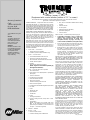
Thank you and congratulations on choosing Miller. Now you can get
the job done and get it done right. We know you don’t have time to do
it any other way.
That’s why when Niels Miller first started building arc welders in 1929,
he made sure his products offered long-lasting value and superior
quality. Like you, his customers couldn’t afford anything less. Miller
products had to be more than the best they could be. They had to be the
best you could buy.
Today, the people that build and sell Miller products continue the
tradition. They’re just as committed to providing equipment and service
that meets the high standards of quality and value established in 1929.
This Owner’s Manual is designed to help you get the most out of your
Miller products. Please take time to read the Safety precautions. They
will help you protect yourself against potential hazards on the worksite.
We’ve made installation and operation quick
and easy. With Miller you can count on years
of reliable service with proper maintenance.
And if for some reason the unit needs repair,
there’s a Troubleshooting section that will
help you figure out what the problem is. The
parts list will then help you to decide the
exact part you may need to fix the problem.
Warranty and service information for your
particular model are also provided.
Miller is the first welding
equipment manufacturer in
the U.S.A. to be registered to
the ISO 9001:2000 Quality
System Standard.
Working as hard as you do
– every power source from
Miller is backed by the most
hassle-free warranty in the
business.
From Miller to You
Miller offers a Technical
Manual which provides
more detailed service and
parts information for your
unit. To obtain a Technical
Manual, contact your local
distributor. Your distributor
can also supply you with
Welding Process Manuals
such as SMAW, GTAW,
GMAW, and GMAW-P.

The following terms are
used interchangeably
throughout this manual:
TIG = GTAW
Stick = SMAW
TABLE OF CONTENTS
SECTION 1 – SAFETY PRECAUTIONS - READ BEFORE USING 1. . . . . . . . . . . . . . . . . . . . . . . . . . . .
1-1. Symbol Usage 1. . . . . . . . . . . . . . . . . . . . . . . . . . . . . . . . . . . . . . . . . . . . . . . . . . . . . . . . . . . . . . . .
1-2. Arc Welding Hazards 1. . . . . . . . . . . . . . . . . . . . . . . . . . . . . . . . . . . . . . . . . . . . . . . . . . . . . . . . . . .
1-3. Additional Symbols for Installation, Operation, and Maintenance 3. . . . . . . . . . . . . . . . . . . . . . .
1-4. Principal Safety Standards 3. . . . . . . . . . . . . . . . . . . . . . . . . . . . . . . . . . . . . . . . . . . . . . . . . . . . . .
1-5. EMF Information 4. . . . . . . . . . . . . . . . . . . . . . . . . . . . . . . . . . . . . . . . . . . . . . . . . . . . . . . . . . . . . . .
SECTION 1 – CONSIGNES DE SECURITE – LIRE AVANT UTILISATION 5. . . . . . . . . . . . . . . . . . . . .
1-1. Signification des symboles 5. . . . . . . . . . . . . . . . . . . . . . . . . . . . . . . . . . . . . . . . . . . . . . . . . . . . . .
1-2. Dangers relatifs au soudage à l’arc 5. . . . . . . . . . . . . . . . . . . . . . . . . . . . . . . . . . . . . . . . . . . . . . .
1-3. Dangers supplémentaires en relation avec l’installation, le fonctionnement et la maintenance 7
1-4. Principales normes de sécurité 8. . . . . . . . . . . . . . . . . . . . . . . . . . . . . . . . . . . . . . . . . . . . . . . . . . .
1-5. Information sur les champs électromagnétiques 8. . . . . . . . . . . . . . . . . . . . . . . . . . . . . . . . . . . . .
SECTION 2 – DEFINITIONS (CE Models Only) 9. . . . . . . . . . . . . . . . . . . . . . . . . . . . . . . . . . . . . . . . . . . .
2-1. Warning Label Definitions 9. . . . . . . . . . . . . . . . . . . . . . . . . . . . . . . . . . . . . . . . . . . . . . . . . . . . . . .
2-2. Manufacturer’s Rating Label For CE Products Only 11. . . . . . . . . . . . . . . . . . . . . . . . . . . . . . . . . .
2-3. Symbols And Definitions 12. . . . . . . . . . . . . . . . . . . . . . . . . . . . . . . . . . . . . . . . . . . . . . . . . . . . . . . .
SECTION 3 – INSTALLATION 13. . . . . . . . . . . . . . . . . . . . . . . . . . . . . . . . . . . . . . . . . . . . . . . . . . . . . . . . . . .
3-1. Specifications 13. . . . . . . . . . . . . . . . . . . . . . . . . . . . . . . . . . . . . . . . . . . . . . . . . . . . . . . . . . . . . . . . .
3-2. Volt-Ampere Curves 14. . . . . . . . . . . . . . . . . . . . . . . . . . . . . . . . . . . . . . . . . . . . . . . . . . . . . . . . . . . .
3-3. Duty Cycle and Overheating 14. . . . . . . . . . . . . . . . . . . . . . . . . . . . . . . . . . . . . . . . . . . . . . . . . . . . .
3-4. Selecting a Location 15. . . . . . . . . . . . . . . . . . . . . . . . . . . . . . . . . . . . . . . . . . . . . . . . . . . . . . . . . . . .
3-5. 115 Volts AC Duplex Receptacle, Circuit Breaker CB1 (Optional), And Power Switch 16. . . . .
3-6. Weld Output Terminals And Selecting Cable Sizes* 16. . . . . . . . . . . . . . . . . . . . . . . . . . . . . . . . . .
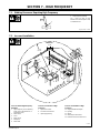
3-7. Remote 14 Receptacle Information 17. . . . . . . . . . . . . . . . . . . . . . . . . . . . . . . . . . . . . . . . . . . . . . .
3-8. Remote Program Select Inputs (Optional For DX Models) 18. . . . . . . . . . . . . . . . . . . . . . . . . . . .
3-9. Automation Connection (LX Models Only) 19. . . . . . . . . . . . . . . . . . . . . . . . . . . . . . . . . . . . . . . . . .
3-10.Gas Connections 20. . . . . . . . . . . . . . . . . . . . . . . . . . . . . . . . . . . . . . . . . . . . . . . . . . . . . . . . . . . . . .
3-11.TIG HF Impulse/ Lift-Arct Connections 20. . . . . . . . . . . . . . . . . . . . . . . . . . . . . . . . . . . . . . . . . . . .
3-12.Stick Connections 21. . . . . . . . . . . . . . . . . . . . . . . . . . . . . . . . . . . . . . . . . . . . . . . . . . . . . . . . . . . . . .
3-13.Electrical Service Guide 22. . . . . . . . . . . . . . . . . . . . . . . . . . . . . . . . . . . . . . . . . . . . . . . . . . . . . . . . .
3-14.Connecting Input Power 23. . . . . . . . . . . . . . . . . . . . . . . . . . . . . . . . . . . . . . . . . . . . . . . . . . . . . . . . .
SECTION 4 – OPERATION 24. . . . . . . . . . . . . . . . . . . . . . . . . . . . . . . . . . . . . . . . . . . . . . . . . . . . . . . . . . . . .
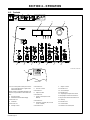
4-1. Controls 24. . . . . . . . . . . . . . . . . . . . . . . . . . . . . . . . . . . . . . . . . . . . . . . . . . . . . . . . . . . . . . . . . . . . . .
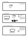
4-2. Amperage Control 25. . . . . . . . . . . . . . . . . . . . . . . . . . . . . . . . . . . . . . . . . . . . . . . . . . . . . . . . . . . . .
4-3. Encoder Control 25. . . . . . . . . . . . . . . . . . . . . . . . . . . . . . . . . . . . . . . . . . . . . . . . . . . . . . . . . . . . . . .
4-4. Ammeter And Volt Meter 25. . . . . . . . . . . . . . . . . . . . . . . . . . . . . . . . . . . . . . . . . . . . . . . . . . . . . . . .
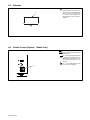
4-5. Polarity Control (Dynastyt Models Only) 26. . . . . . . . . . . . . . . . . . . . . . . . . . . . . . . . . . . . . . . . . . .
4-6. Process Control 26. . . . . . . . . . . . . . . . . . . . . . . . . . . . . . . . . . . . . . . . . . . . . . . . . . . . . . . . . . . . . . .
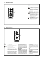
4-7. Output Control 27. . . . . . . . . . . . . . . . . . . . . . . . . . . . . . . . . . . . . . . . . . . . . . . . . . . . . . . . . . . . . . . . .
4-8. Pulser Control (DX And LX Models) 28. . . . . . . . . . . . . . . . . . . . . . . . . . . . . . . . . . . . . . . . . . . . . . .
4-9. Sequencer Controls (DX, LX And All CE Models) 29. . . . . . . . . . . . . . . . . . . . . . . . . . . . . . . . . . . .
4-10.Adjust Controls (Preflow/Post Flow/DIG) 30. . . . . . . . . . . . . . . . . . . . . . . . . . . . . . . . . . . . . . . . . . .
4-11.AC Waveshape (Dynasty Models Only) 31. . . . . . . . . . . . . . . . . . . . . . . . . . . . . . . . . . . . . . . . . . . .
4-12.Spot Time Control (All Models) 31. . . . . . . . . . . . . . . . . . . . . . . . . . . . . . . . . . . . . . . . . . . . . . . . . . .
4-13.Memory (Program Storage Locations 1-4) (DX And LX Models If Available) 32. . . . . . . . . . . . . .
4-14.Setting Preflow Time For Use With TIG HF Impulse On Models That Do Not Have A Preflow
Control On The Front Panel 33. . . . . . . . . . . . . . . . . . . . . . . . . . . . . . . . . . . . . . . . . . . . . . . . . . . . . . . . .
4-15.Factory Parameter Defaults And Range And Resolution 34. . . . . . . . . . . . . . . . . . . . . . . . . . . . . .
4-16.Resetting Unit To Factory Default Settings (All Models) 35. . . . . . . . . . . . . . . . . . . . . . . . . . . . . . .
4-17.Advanced Functions 36. . . . . . . . . . . . . . . . . . . . . . . . . . . . . . . . . . . . . . . . . . . . . . . . . . . . . . . . . . . .
4-18.Output Control And Trigger Functions 39. . . . . . . . . . . . . . . . . . . . . . . . . . . . . . . . . . . . . . . . . . . . .
4-19.Arc Timer/Counter Display (All Models) 47. . . . . . . . . . . . . . . . . . . . . . . . . . . . . . . . . . . . . . . . . . . .
4-20.Lockout Functions 48. . . . . . . . . . . . . . . . . . . . . . . . . . . . . . . . . . . . . . . . . . . . . . . . . . . . . . . . . . . . .
WARNING
This product, when used
for welding or cutting,
produces fumes or
gases which contain
chemicals known to the
State of California to
cause birth defects and,
in some cases, cancer.
(California Health &
Safety Code Section
25249.5 et seq.)
(Continued)

TABLE OF CONTENTS
SECTION 5 – MAINTENANCE AND TROUBLESHOOTING 51. . . . . . . . . . . . . . . . . . . . . . . . . . . . . . . . .
5-2. Blowing Out Inside of Unit 51. . . . . . . . . . . . . . . . . . . . . . . . . . . . . . . . . . . . . . . . . . . . . . . . . . . . . . .
5-3. Voltmeter/Ammeter Help Displays 52. . . . . . . . . . . . . . . . . . . . . . . . . . . . . . . . . . . . . . . . . . . . . . . .
5-4. Troubleshooting 53. . . . . . . . . . . . . . . . . . . . . . . . . . . . . . . . . . . . . . . . . . . . . . . . . . . . . . . . . . . . . . .
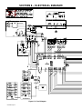
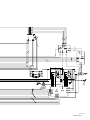
SECTION 6 – ELECTRICAL DIAGRAM 54. . . . . . . . . . . . . . . . . . . . . . . . . . . . . . . . . . . . . . . . . . . . . . . . . . .
SECTION 7 – HIGH FREQUENCY 56. . . . . . . . . . . . . . . . . . . . . . . . . . . . . . . . . . . . . . . . . . . . . . . . . . . . . . .
7-1. Welding Processes Requiring High Frequency 56. . . . . . . . . . . . . . . . . . . . . . . . . . . . . . . . . . . . . .
7-2. Incorrect Installation 56. . . . . . . . . . . . . . . . . . . . . . . . . . . . . . . . . . . . . . . . . . . . . . . . . . . . . . . . . . . .
7-3. Correct Installation 57. . . . . . . . . . . . . . . . . . . . . . . . . . . . . . . . . . . . . . . . . . . . . . . . . . . . . . . . . . . . .
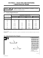
SECTION 8 – SELECTING AND PREPARING
TUNGSTEN ELECTRODE 58. . . . . . . . . . . . . . . . . . . . . . . . . . . . . . . . . . . . . . . . . . . . . . . . . . . . . . . . . . . . . .
8-1. Selecting Tungsten Electrode 58. . . . . . . . . . . . . . . . . . . . . . . . . . . . . . . . . . . . . . . . . . . . . . . . . . . .
8-2. Safety Information About Tungsten 58. . . . . . . . . . . . . . . . . . . . . . . . . . . . . . . . . . . . . . . . . . . . . . .
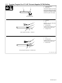
8-3. Preparing Tungsten For AC Or DC Electrode Negative (DCEN) Welding 59. . . . . . . . . . . . . . . .
SECTION 9 – GUIDELINES FOR TIG WELDING (GTAW) 60. . . . . . . . . . . . . . . . . . . . . . . . . . . . . . . . . . .
SECTION 10 – STICK WELDING (SMAW) GUIDELINES 66. . . . . . . . . . . . . . . . . . . . . . . . . . . . . . . . . . . .
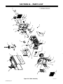
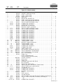
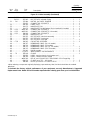
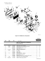
SECTION 11 – PARTS LIST 76. . . . . . . . . . . . . . . . . . . . . . . . . . . . . . . . . . . . . . . . . . . . . . . . . . . . . . . . . . . . .
OPTIONS AND ACCESSORIES
WARRANTY

dec_con1_11/02
Declaration of Conformity For
European Community (CE) Products
This information is provided for units with CE certification (see rating label on unit.)
NOTE
Manufacturer’s Name: Miller Electric Mfg. Co.
Manufacturer’s Address: 1635 W. Spencer Street
Appleton, WI 54914 USA
Declares that the product: Dynasty
R
300 SD, DX, LX
conforms to the following Directives and Standards:
Directives
Low Voltage Directive: 73/23/EEC
Machinery Directives: 89/392/EEC, 91/368/EEC, 93/C 133/04, 93/68/EEC
Electromagnetic Capability Directives: 89/336, 92/31/EEC
Standards
Safety Requirements for Arc Welding Equipment part 1: EN 60974-1: 1990
Arc Welding Equipment Part 1: Welding Power Sources: IEC 974-1
(December 1996 – Draft revision)
Degrees of Protection provided by Enclosures (IP code): IEC 529: 1989
Insulation coordination for equipment within low-voltage systems:
Part 1: Principles, requirements and tests: IEC 664-1: 1992
Electromagnetic compatibility (EMC) Product standard for arc welding equipment:
EN50199: August 1995
European Contact: Mr. Danilo Fedolfi, Managing Director
ITW WELDING PRODUCTS ITALY S.r.l.
Via Privata Iseo 6/E
20098 San Giuliano
Milanese, Italy
Telephone: 39(02)98290-1
Fax: 39(02)98290-203


OM-358 Page 1
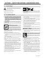
SECTION 1 – SAFETY PRECAUTIONS - READ BEFORE USING
som _nd_7/02
1-1. Symbol Usage
Means Warning! Watch Out! There are possible hazards
with this procedure! The possible hazards are shown in
the adjoining symbols.
Y Marks a special safety message.
. Means “Note”; not safety related.
This group of symbols means Warning! Watch Out! possible
ELECTRIC SHOCK, MOVING PARTS, and HOT PARTS hazards.
Consult symbols and related instructions below for necessary actions
to avoid the hazards.
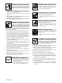
1-2. Arc Welding Hazards
Y The symbols shown below are used throughout this manual to
call attention to and identify possible hazards. When you see
the symbol, watch out, and follow the related instructions to
avoid the hazard. The safety information given below is only
a summary of the more complete safety information found in
the Safety Standards listed in Section 1-4. Read and follow all
Safety Standards.
Y Only qualified persons should install, operate, maintain, and
repair this unit.
Y During operation, keep everybody, especially children, away.
ELECTRIC SHOCK can kill.
Touching live electrical parts can cause fatal shocks
or severe burns. The electrode and work circuit is
electrically live whenever the output is on. The input
power circuit and machine internal circuits are also
live when power is on. In semiautomatic or automatic wire welding, the
wire, wire reel, drive roll housing, and all metal parts touching the
welding wire are electrically live. Incorrectly installed or improperly
grounded equipment is a hazard.
D Do not touch live electrical parts.
D Wear dry, hole-free insulating gloves and body protection.
D Insulate yourself from work and ground using dry insulating mats
or covers big enough to prevent any physical contact with the work
or ground.
D Do not use AC output in damp areas, if movement is confined, or if
there is a danger of falling.
D Use AC output ONLY if required for the welding process.
D If AC output is required, use remote output control if present on
unit.
D Disconnect input power or stop engine before installing or
servicing this equipment. Lockout/tagout input power according to
OSHA 29 CFR 1910.147 (see Safety Standards).
D Properly install and ground this equipment according to its
Owner’s Manual and national, state, and local codes.
D Always verify the supply ground – check and be sure that input
power cord ground wire is properly connected to ground terminal in
disconnect box or that cord plug is connected to a properly
grounded receptacle outlet.
D When making input connections, attach proper grounding conduc-
tor first – double-check connections.
D Frequently inspect input power cord for damage or bare wiring –
replace cord immediately if damaged – bare wiring can kill.
D Turn off all equipment when not in use.
D Do not use worn, damaged, undersized, or poorly spliced cables.
D Do not drape cables over your body.
D If earth grounding of the workpiece is required, ground it directly
with a separate cable.
D Do not touch electrode if you are in contact with the work, ground,
or another electrode from a different machine.
D Use only well-maintained equipment. Repair or replace damaged
parts at once. Maintain unit according to manual.
D Wear a safety harness if working above floor level.
D Keep all panels and covers securely in place.
D Clamp work cable with good metal-to-metal contact to workpiece
or worktable as near the weld as practical.
D Insulate work clamp when not connected to workpiece to prevent
contact with any metal object.
D Do not connect more than one electrode or work cable to any
single weld output terminal.
SIGNIFICANT DC VOLTAGE exists after removal of
input power on inverters.
D Turn Off inverter, disconnect input power, and discharge input
capacitors according to instructions in Maintenance Section
before touching any parts.
Welding produces fumes and gases. Breathing
these fumes and gases can be hazardous to your
health.
FUMES AND GASES can be hazardous.
D Keep your head out of the fumes. Do not breathe the fumes.
D If inside, ventilate the area and/or use exhaust at the arc to remove
welding fumes and gases.
D If ventilation is poor, use an approved air-supplied respirator.
D Read the Material Safety Data Sheets (MSDSs) and the
manufacturer’s instructions for metals, consumables, coatings,
cleaners, and degreasers.
D Work in a confined space only if it is well ventilated, or while
wearing an air-supplied respirator. Always have a trained watch-
person nearby. Welding fumes and gases can displace air and
lower the oxygen level causing injury or death. Be sure the breath-
ing air is safe.
D Do not weld in locations near degreasing, cleaning, or spraying op-
erations. The heat and rays of the arc can react with vapors to form
highly toxic and irritating gases.
D Do not weld on coated metals, such as galvanized, lead, or
cadmium plated steel, unless the coating is removed from the weld
area, the area is well ventilated, and if necessary, while wearing an
air-supplied respirator. The coatings and any metals containing
these elements can give off toxic fumes if welded.

OM-358 Page 2
Arc rays from the welding process produce intense
visible and invisible (ultraviolet and infrared) rays
that can burn eyes and skin. Sparks fly off from the
weld.
ARC RAYS can burn eyes and skin.
D Wear a welding helmet fitted with a proper shade of filter to protect
your face and eyes when welding or watching (see ANSI Z49.1
and Z87.1 listed in Safety Standards).
D Wear approved safety glasses with side shields under your
helmet.
D Use protective screens or barriers to protect others from flash and
glare; warn others not to watch the arc.
D Wear protective clothing made from durable, flame-resistant mate-
rial (leather and wool) and foot protection.
Welding on closed containers, such as tanks,
drums, or pipes, can cause them to blow up. Sparks
can fly off from the welding arc. The flying sparks, hot
workpiece, and hot equipment can cause fires and
burns. Accidental contact of electrode to metal objects can cause
sparks, explosion, overheating, or fire. Check and be sure the area is
safe before doing any welding.
WELDING can cause fire or explosion.
D Protect yourself and others from flying sparks and hot metal.
D Do not weld where flying sparks can strike flammable material.
D Remove all flammables within 35 ft (10.7 m) of the welding arc. If
this is not possible, tightly cover them with approved covers.
D Be alert that welding sparks and hot materials from welding can
easily go through small cracks and openings to adjacent areas.
D Watch for fire, and keep a fire extinguisher nearby.
D Be aware that welding on a ceiling, floor, bulkhead, or partition can
cause fire on the hidden side.
D Do not weld on closed containers such as tanks, drums, or pipes,
unless they are properly prepared according to AWS F4.1 (see
Safety Standards).
D Connect work cable to the work as close to the welding area as
practical to prevent welding current from traveling long, possibly
unknown paths and causing electric shock and fire hazards.
D Do not use welder to thaw frozen pipes.
D Remove stick electrode from holder or cut off welding wire at
contact tip when not in use.
D Wear oil-free protective garments such as leather gloves, heavy
shirt, cuffless trousers, high shoes, and a cap.
D Remove any combustibles, such as a butane lighter or matches,
from your person before doing any welding.
FLYING METAL can injure eyes.
D Welding, chipping, wire brushing, and grinding
cause sparks and flying metal. As welds cool,
they can throw off slag.
D Wear approved safety glasses with side
shields even under your welding helmet.
BUILDUP OF GAS can injure or kill.
D Shut off shielding gas supply when not in use.
D Always ventilate confined spaces or use
approved air-supplied respirator.
HOT PARTS can cause severe burns.
D Do not touch hot parts bare handed.
D Allow cooling period before working on gun or
torch.
MAGNETIC FIELDS can affect pacemakers.
D Pacemaker wearers keep away.
D Wearers should consult their doctor before
going near arc welding, gouging, or spot
welding operations.
NOISE can damage hearing.
Noise from some processes or equipment can
damage hearing.
D Wear approved ear protection if noise level is
high.
Shielding gas cylinders contain gas under high
pressure. If damaged, a cylinder can explode. Since
gas cylinders are normally part of the welding
process, be sure to treat them carefully.
CYLINDERS can explode if damaged.
D Protect compressed gas cylinders from excessive heat, mechani-
cal shocks, slag, open flames, sparks, and arcs.
D Install cylinders in an upright position by securing to a stationary
support or cylinder rack to prevent falling or tipping.
D Keep cylinders away from any welding or other electrical circuits.
D Never drape a welding torch over a gas cylinder.
D Never allow a welding electrode to touch any cylinder.
D Never weld on a pressurized cylinder – explosion will result.
D Use only correct shielding gas cylinders, regulators, hoses, and fit-
tings designed for the specific application; maintain them and
associated parts in good condition.
D Turn face away from valve outlet when opening cylinder valve.
D Keep protective cap in place over valve except when cylinder is in
use or connected for use.
D Read and follow instructions on compressed gas cylinders,
associated equipment, and CGA publication P-1 listed in Safety
Standards.

OM-358 Page 3
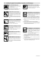
1-3. Additional Symbols For Installation, Operation, And Maintenance
FIRE OR EXPLOSION hazard.
D Do not install or place unit on, over, or near
combustible surfaces.
D Do not install unit near flammables.
D Do not overload building wiring – be sure power supply system is
properly sized, rated, and protected to handle this unit.
FALLING UNIT can cause injury.
D Use lifting eye to lift unit only, NOT running
gear, gas cylinders, or any other accessories.
D Use equipment of adequate capacity to lift and
support unit.
D If using lift forks to move unit, be sure forks are
long enough to extend beyond opposite side of
unit.
OVERUSE can cause OVERHEATING
D Allow cooling period; follow rated duty cycle.
D Reduce current or reduce duty cycle before
starting to weld again.
D Do not block or filter airflow to unit.
STATIC (ESD) can damage PC boards.
D Put on grounded wrist strap BEFORE handling
boards or parts.
D Use proper static-proof bags and boxes to
store, move, or ship PC boards.
MOVING PARTS can cause injury.
D Keep away from moving parts.
D Keep away from pinch points such as drive
rolls.
WELDING WIRE can cause injury.
D Do not press gun trigger until instructed to do
so.
D Do not point gun toward any part of the body,
other people, or any metal when threading
welding wire.
MOVING PARTS can cause injury.
D Keep away from moving parts such as fans.
D Keep all doors, panels, covers, and guards
closed and securely in place.
H.F. RADIATION can cause interference.
D High-frequency (H.F.) can interfere with radio
navigation, safety services, computers, and
communications equipment.
D Have only qualified persons familiar with
electronic equipment perform this installation.
D The user is responsible for having a qualified electrician prompt-
ly correct any interference problem resulting from the installa-
tion.
D If notified by the FCC about interference, stop using the
equipment at once.
D Have the installation regularly checked and maintained.
D Keep high-frequency source doors and panels tightly shut, keep
spark gaps at correct setting, and use grounding and shielding to
minimize the possibility of interference.
ARC WELDING can cause interference.
D Electromagnetic energy can interfere with
sensitive electronic equipment such as
computers and computer-driven equipment
such as robots.
D Be sure all equipment in the welding area is
electromagnetically compatible.
D To reduce possible interference, keep weld cables as short as
possible, close together, and down low, such as on the floor.
D Locate welding operation 100 meters from any sensitive elec-
tronic equipment.
D Be sure this welding machine is installed and grounded
according to this manual.
D If interference still occurs, the user must take extra measures
such as moving the welding machine, using shielded cables,
using line filters, or shielding the work area.

OM-358 Page 4
1-4. Principal Safety Standards
Safety in Welding, Cutting, and Allied Processes, ANSI Standard Z49.1,
from American Welding Society, 550 N.W. LeJeune Rd, Miami FL 33126
(phone: 305-443-9353, website: www.aws.org).
Recommended Safe Practices for the Preparation for Welding and Cut-
ting of Containers and Piping, American Welding Society Standard
AWS F4.1, from American Welding Society, 550 N.W. LeJeune Rd, Mi-
ami, FL 33126 (phone: 305-443-9353, website: www.aws.org).
National Electrical Code, NFPA Standard 70, from National Fire Protec-
tion Association, P.O. Box 9101, 1 Battery March Park, Quincy, MA
02269–9101 (phone: 617–770–3000, website: www.nfpa.org and www.
sparky.org).
Safe Handling of Compressed Gases in Cylinders, CGA Pamphlet P-1,
from Compressed Gas Association, 1735 Jefferson Davis Highway,
Suite 1004, Arlington, VA 22202–4102 (phone: 703–412–0900, web-
site: www.cganet.com).
Code for Safety in Welding and Cutting, CSA Standard W117.2, from
Canadian Standards Association, Standards Sales, 178 Rexdale
Boulevard, Rexdale, Ontario, Canada M9W 1R3 (phone:
800–463–6727 or in Toronto 416–747–4044, website: www.csa–in-
ternational.org).
Practice For Occupational And Educational Eye And Face Protection,
ANSI Standard Z87.1, from American National Standards Institute, 11
West 42nd Street, New York, NY 10036–8002 (phone: 212–642–4900,
website: www.ansi.org).
Standard for Fire Prevention During Welding, Cutting, and Other Hot
Work, NFPA Standard 51B, from National Fire Protection Association,
P.O. Box 9101, 1 Battery March Park, Quincy, MA 02269–9101 (phone:
617–770–3000, website: www.nfpa.org and www. sparky.org).
OSHA, Occupational Safety and Health Standards for General Indus-
try, Title 29, Code of Federal Regulations (CFR), Part 1910, Subpart Q,
and Part 1926, Subpart J, from U.S. Government Printing Office, Super-
intendent of Documents, P.O. Box 371954, Pittsburgh, PA 15250 (there
are 10 Regional Offices––phone for Region 5, Chicago, is
312–353–2220, website: www.osha.gov).
1-5. EMF Information
Considerations About Welding And The Effects Of Low Frequency
Electric And Magnetic Fields
Welding current, as it flows through welding cables, will cause electro-
magnetic fields. There has been and still is some concern about such
fields. However, after examining more than 500 studies spanning 17
years of research, a special blue ribbon committee of the National
Research Council concluded that: “The body of evidence, in the
committee’s judgment, has not demonstrated that exposure to power-
frequency electric and magnetic fields is a human-health hazard.”
However, studies are still going forth and evidence continues to be
examined. Until the final conclusions of the research are reached, you
may wish to minimize your exposure to electromagnetic fields when
welding or cutting.
To reduce magnetic fields in the workplace, use the following
procedures:
1. Keep cables close together by twisting or taping them.
2. Arrange cables to one side and away from the operator.
3. Do not coil or drape cables around your body.
4. Keep welding power source and cables as far away from opera-
tor as practical.
5. Connect work clamp to workpiece as close to the weld as possi-
ble.
About Pacemakers:
Pacemaker wearers consult your doctor first. If cleared by your doctor,
then following the above procedures is recommended.

OM-358 Page 5
SECTION 1 – CONSIGNES DE SÉCURITÉ – À LIRE AVANT
UTILISATION
som _nd_fre 7/02
1-1. Signification des symboles
Signifie « Mise en garde. Faire preuve de vigilance. »
Cette procédure présente des risques identifiés par les
symboles adjacents aux directives.
Y Identifie un message de sécurité particulier.
. Signifie « NOTA » ; n’est pas relatif à la sécurité.
Ce groupe de symboles signifie « Mise en garde. Faire preuve de vigi-
lance. » Il y a des dangers liés aux CHOCS ÉLECTRIQUES, aux
PIÈCES EN MOUVEMENT et aux PIÈCES CHAUDES. Se reporter
aux symboles et aux directives ci-dessous afin de connaître les me-
sures à prendre pour éviter tout danger.
1-2. Dangers relatifs au soudage à l’arc
Y Les symboles ci-après sont utilisés tout au long du présent
manuel pour attirer l’attention sur les dangers potentiels et les
identifier. Lorsqu’on voit un symbole, faire preuve de vigilance et
suivre les directives mentionnées afin d’éviter tout danger. Les
consignes de sécurité énoncées ci-après ne font que résumer le
contenu des normes de sécurité mentionnées à la section 1–4.
Lire et respecter toutes ces normes.
Y L’installation, l’utilisation, l’entretien et les réparations ne doi-
vent être confiés qu’à des personnes qualifiées.
Y Pendant l’utilisation de l’appareil, tenir à l’écart toute personne,
en particulier les enfants.
LES DÉCHARGES ÉLECTRIQUES
peuvent être mortelles.
Un simple contact avec des pièces sous tension peut
causer une électrocution ou des blessures graves.
L’électrode et le circuit de soudage sont sous tension
dès que l’appareil est en fonctionnement. Le circuit
d’entrée et les circuits internes de l’appareil sont également sous tension.
En soudage semi–automatique ou automatique, le fil, le dévidoir, le
logement des galets d’entraînement et les pièces métalliques en contact
avec le fil de soudage sont sous tension. Tout matériel mal installé ou mal
mis à la terre présente un danger.
D Ne jamais toucher aux pièces électriques sous tension.
D Porter des gants et des vêtements de protection secs et exempts de
trous.
D S’isoler de la pièce et de la terre au moyen de tapis ou autres disposi-
tifs isolants suffisamment grands pour empêcher tout contact
physique avec la pièce ou la terre.
D Ne pas se servir d’une source de courant alternatif dans les zones humi-
des, les endroits confinés ou là où on risque de tomber.
D Ne se servir d’une source de courant alternatif QUE si le procédé de souda-
ge l’exige.
D Si l’utilisation d’une source de courant alternatif s’avère nécessaire, se ser-
vir de la fonction de télécommande si l’appareil en est équipé.
D Couper l’alimentation ou arrêter le moteur avant de procéder à l’instal-
lation, à la réparation ou à l’entretien de l’appareil. Couper/étiqueter
l’alimentation selon la norme OSHA 29 CFR 1910.147 (voir les nor-
mes de sécurité).
D Installer et mettre à la terre correctement l’appareil conformément à
son manuel d’utilisation et aux codes nationaux, provinciaux et
municipaux.
D Toujours vérifier la terre du cordon d’alimentation – Vérifier et s’assu-
rer que le fil de terre du cordon d’alimentation est bien raccordé à la
borne de terre du sectionneur ou que la fiche du cordon est raccordée
à une prise correctement mise à la terre.
D Pour exécuter les branchements d’entrée, fixer d’abord le conducteur
de mise à la terre adéquat et contre–vérifier les connexions.
D Vérifier fréquemment le cordon d’alimentation et s’assurer qu’il n’est
ni endommagé ni dénudé ; le remplacer immédiatement s’il est en-
dommagé – tout câble dénudé peut causer une électrocution.
D Mettre l’appareil hors tension quand on ne l’utilise pas.
D Ne pas utiliser de câbles usés, endommagés, de calibre insuffisant ou
mal épissés.
D Ne pas s’enrouler les câbles autour du corps.
D Si la pièce soudée doit être mise à la terre, le faire directement avec un
câble distinct.
D Ne pas toucher l’électrode quand on est en contact avec la pièce, la
terre ou une électrode d’une autre machine.
D N’utiliser que du matériel en bon état. Réparer ou remplacer sur–le–
champ les pièces endommagées. Entretenir l’appareil conformément
au présent manuel.
D Porter un harnais de sécurité quand on travaille en hauteur.
D Maintenir solidement en place tous les panneaux et capots.
D Fixer le câble de retour de façon à obtenir un bon contact métal sur
métal avec la pièce à souder ou la table de travail, le plus près possible
de la soudure.
D Ne pas connecter plus d’une électrode ou plus d’un câble de masse à un
même terminal de sortie.
Il subsiste un COURANT CONTINU IMPORTANT
dans les convertisseurs après la suppression de
l’alimentation électrique.
D Arrêter les convertisseurs, débrancher le courant électrique et dé-
charger les condensateurs d’alimentation selon les instructions
énoncées à la section Entretien avant de toucher les pièces.
Le soudage génère des fumées et des gaz dont
l’inhalation peut être dangereuse pour la santé.
LES FUMÉES ET LES GAZ peuvent
être dangereux.
D Se tenir à distance des fumées et ne pas les inhaler.
D À l’intérieur, ventiler la zone et/ou utiliser un dispositif d’aspiration au
niveau de l’arc pour l’évacuation des fumées et des gaz de soudage.
D Si la ventilation est insuffisante, utiliser un respirateur à adduction
d’air agréé.
D Lire les fiches techniques de santé–sécurité (FTSS) et les instruc-
tions du fabricant concernant les métaux, les consommables, les
revêtements, les nettoyants et les dégraisseurs.
D Ne travailler dans un espace clos que s’il est bien ventilé ou porter un
respirateur à adduction d’air. Demander toujours à un surveillant dû-
ment formé de se tenir à proximité. Des fumées et des gaz de soudage
peuvent se substituer à l’air, abaisser la teneur en oxygène et causer
des lésions ou des accidents mortels. S’assurer que l’air est respira-
ble.
D Ne pas souder à proximité d’opérations de dégraissage, de nettoyage
ou de pulvérisation. La chaleur et les rayons de l’arc peuvent réagir en
présence de vapeurs et former des gaz hautement toxiques et irri-
tants.
D Ne pas souder de métaux munis d’un revêtement, tels que la tôle
d’acier galvanisée, plombée ou cadmiée, à moins que le revêtement
n’ait été enlevé dans la zone de soudage, que l’endroit soit bien venti-
lé, et si nécessaire, porter un respirateur à adduction d’air. Les
revêtements et tous les métaux renfermant ces éléments peuvent dé-
gager des fumées toxiques lorsqu’on les soude.

OM-358 Page 6
Le rayonnement de l’arc génère des rayons visibles et
invisibles intenses (ultraviolets et infrarouges) suscep-
tibles de causer des brûlures oculaires et cutanées.
Des étincelles sont projetées pendant le soudage.
LES RAYONS DE L’ARC peuvent cau-
ser des brûlures oculaires et cuta-
nées.
D Porter un masque de soudage muni d’un filtre de la nuance adéquate
pour se protéger le visage et les yeux pendant le soudage ou pour re-
garder (voir les normes de sécurité ANSI Z49.1 et Z87.1).
D Porter des lunettes de sécurité à écrans latéraux sous le masque.
D Utiliser des écrans ou des barrières pour protéger les tiers de l’éclat
éblouissant ou aveuglant de l’arc ; leur demander de ne pas regarder
l’arc.
D Porter des vêtements de protection en matière durable et ignifuge
(cuir ou laine) et des chaussures de sécurité.
Le soudage effectué sur des récipients fermés tels que
des réservoirs, des fûts ou des conduites peut causer
leur éclatement. Des étincelles peuvent être projetées
de l’arc de soudure. La projection d’étincelles, les
pièces chaudes et les équipements chauds peuvent causer des
incendies et des brûlures. Le contact accidentel de l’électrode avec tout
objet métallique peut causer des étincelles, une explosion, un surchauf-
fement ou un incendie. Avant de commencer le soudage, vérifier et
s’assurer que l’endroit ne présente pas de danger.
LE SOUDAGE peut causer un incen-
die ou une explosion.
D Se protéger et protéger les tiers de la projection d’étincelles et de mé-
tal chaud.
D Ne pas souder à un endroit où des étincelles peuvent tomber sur des
substances inflammables.
D Placer toutes les substances inflammables à une distance de 10,7 m
de l’arc de soudage. En cas d’impossibilité, les recouvrir soigneuse-
ment avec des protections agréées.
D Des étincelles et des matières en fusion peuvent facilement passer
même par des fissures et des ouvertures de petites dimensions.
D Surveiller tout déclenchement d’incendie et tenir un extincteur à proxi-
mité.
D Le soudage effectué sur un plafond, un plancher, une paroi ou une
cloison peut déclencher un incendie de l’autre côté.
D Ne pas souder des récipients fermés tels que des réservoirs, des fûts
ou des conduites, à moins qu’ils n’aient été préparés conformément à
l’AWS F4.1 (voir les normes de sécurité).
D Brancher le câble sur la pièce le plus près possible de la zone de sou-
dage pour éviter que le courant ne circule sur une longue distance, par
des chemins inconnus, et ne cause des risques d’électrocution et d’in-
cendie.
D Ne pas utiliser le poste de soudage pour dégeler des conduites ge-
lées.
D En cas de non utilisation, enlever la baguette d’électrode du porte–
électrode ou couper le fil au raz du tube–contact.
D Porter des vêtements de protection exempts d’huile tels que des
gants en cuir, une chemise en tissu épais, des pantalons sans revers,
des chaussures montantes et un masque.
D Avant de souder, retirer tout produit combustible de ses poches, tel
qu’un briquet au butane ou des allumettes.
LES PARTICULES PROJETÉES peu-
vent blesser les yeux.
D Le soudage, le burinage, le passage de la pièce à
la brosse métallique et le meulage provoquent
l’émission d’étincelles et de particules métalli-
ques. Pendant leur refroidissement, les soudures risquent de projeter du
laitier.
D Porter des lunettes de sécurité à écrans latéraux agréés, même sous le
masque de soudage.
LES ACCUMULATIONS DE GAZ peu-
vent causer des blessures ou même
la mort.
D Couper l’alimentation en gaz protecteur en cas de
non utilisation.
D Veiller toujours à bien ventiler les espaces confinés ou porter un respira-
teur à adduction d’air agréé.
LES PIÈCES CHAUDES peuvent cau-
ser des brûlures graves.
D Ne pas toucher les pièces chaudes à main nue.
D Prévoir une période de refroidissement avant
d’utiliser le pistolet ou la torche.
LES CHAMPS MAGNÉTIQUES peuvent
perturber le fonctionnement des stimu-
lateurs cardiaques.
D Les personnes qui portent un stimulateur cardiaque
doivent se tenir à distance.
D Ils doivent consulter leur médecin avant de s’appro-
cher d’un lieu où on exécute des opérations de sou-
dage à l’arc, de gougeage ou de soudage par points.
LE BRUIT peut affecter l’ouïe.
Le bruit de certains processus et équipements peut
affecter l’ouïe.
D Porter des protecteurs d’oreille agréés si le niveau
sonore est trop élevé.
Les bouteilles de gaz protecteur contiennent du gaz
sous haute pression. Toute bouteille endommagée
peut exploser. Comme les bouteilles de gaz font
normalement partie du procédé de soudage, les
manipuler avec précaution.
Les BOUTEILLES endommagées
peuvent exploser.
D Protéger les bouteilles de gaz comprimé de la chaleur excessive, des
chocs mécaniques, du laitier, des flammes nues, des étincelles et des
arcs.
D Placer les bouteilles debout en les fixant dans un support stationnaire
ou dans un porte–bouteilles pour les empêcher de tomber ou de se
renverser.
D Tenir les bouteilles éloignées des circuits de soudage ou autres cir-
cuits électriques.
D Ne jamais poser une torche de soudage sur une bouteille de gaz.
D Ne jamais mettre une électrode de soudage en contact avec une bou-
teille de gaz.
D Ne jamais souder une bouteille contenant du gaz sous pression – elle
risquerait d’exploser.
D N’utiliser que les bouteilles de gaz protecteur, régulateurs, tuyaux et
raccords adéquats pour l’application envisagée ; les maintenir en bon
état, ainsi que les pièces connexes.
D Détourner la tête lorsqu’on ouvre la soupape d’une bouteille.
D Laisser le capuchon protecteur sur la soupape, sauf en cas d’utilisa-
tion ou de branchement de la bouteille
D Lire et suivre les instructions concernant les bouteilles de gaz compri-
mé, les équipements associés et les publications P–1 de la CGA,
mentionnées dans les normes de sécurité.

OM-358 Page 7
1-3. Autres symboles relatifs à l’installation, au fonctionnement et à l’entretien de
l’appareil.
Risque D’INCENDIE OU D’EXPLO-
SION
D Ne pas placer l’appareil sur une surface inflam-
mable, ni au–dessus ou à proximité d’elle.
D Ne pas installer l’appareil à proximité de produits inflammables.
D Ne pas surcharger l’installation électrique – s’assurer que l’alimen-
tation est correctement dimensionnée et protégée avant de mettre
l’appareil en service.
LA CHUTE DE L’APPAREIL peut
blesser.
D N’utiliser que l’anneau de levage pour lever l’ap-
pareil. NE PAS utiliser le chariot, les bouteilles de
gaz ou tout autre accessoire.
D Utiliser un engin de capacité adéquate pour lever
l’appareil.
D Si on utilise un chariot élévateur pour déplacer l’unité, s’assurer que
les fourches sont suffisamment longues pour dépasser du côté op-
posé de l’appareil.
L’EMPLOI EXCESSIF peut FAIRE
SURCHAUFFER L’ÉQUIPEMENT.
D Prévoir une période de refroidissement ; respec-
ter le cycle opératoire nominal.
D Réduire le courant ou le cycle opératoire avant de
reprendre le soudage.
D Ne pas obstruer les orifices ou filtrer l’alimentation en air du poste.
LES CHARGES ÉLECTROSTATI-
QUES peuvent endommager les cir-
cuits imprimés.
D Mettre un bracelet antistatique AVANT de mani-
puler des cartes ou des pièces.
D Utiliser des pochettes et des boîtes antistatiques
pour stocker, déplacer ou expédier des cartes de
circuits imprimés.
LES PIÈCES MOBILES peuvent cau-
ser des blessures.
D Se tenir à l’écart des pièces mobiles.
D Se tenir à l’écart des points de coincement tels
que les dévidoirs.
LES FILS DE SOUDAGE peuvent cau-
ser des blessures.
D Ne pas appuyer sur la gâchette avant d’en avoir
reçu l’instruction.
D Ne pas diriger le pistolet vers soi, vers d’autres
personnes ou vers toute pièce mécanique en en-
gageant le fil de soudage.
LES ORGANES MOBILES peuvent
causer des blessures.
D Se tenir à l’écart des organes mobiles comme les
ventilateurs.
D Maintenir fermés et bien fixés les portes,
panneaux, recouvrements et dispositifs de
protection.
LE RAYONNEMENT HAUTE FRÉ-
QUENCE (H. F.) risque de causer des
interférences.
D Le rayonnement haute fréquence peut causer
des interférences avec les équipements de radio-
navigation et de communication, les services de
sécurité et les ordinateurs.
D Ne demander qu’à des personnes qualifiées familiarisées avec les
équipements électroniques de faire fonctionner l’installation.
D L’utilisateur est tenu de faire corriger rapidement par un électricien
qualifié les interférences causées par l’installation.
D Si la Federal Communications Commission signale des interféren-
ces, arrêter immédiatement l’appareil.
D Faire régulièrement contrôler et entretenir l’installation.
D Maintenir soigneusement fermés les panneaux et les portes des sour-
ces de haute fréquence, maintenir le jeu d’éclatement au réglage
adéquat et utiliser une terre et un blindage pour réduire les interféren-
ces éventuelles.
LE SOUDAGE À L’ARC peut causer
des interférences.
D L’énergie électromagnétique peut causer des
interférences avec l’équipement électronique
sensible tel que les ordinateurs et l’équipement
commandé par ordinateur tel que les robots.
D Veiller à ce que tout l’équipement de la zone de soudage soit compati-
ble au point de vue électromagnétique.
D Pour réduire la possibilité d’interférence, maintenir les câbles de sou-
dage aussi courts que possible, les grouper, et les poser aussi bas
que possible (par ex. : à terre).
D Veiller à souder à une distance de 100 mètres de tout équipement
électronique sensible.
D Veiller à ce que le poste de soudage soit posé et mis à la terre confor-
mément au présent manuel.
D En cas d’interférences après exécution des directives précédentes, il
incombe à l’utilisateur de prendre des mesures supplémentaires tel-
les que le déplacement du poste, l’utilisation de câbles blindés,
l’utilisation de filtres de ligne ou la pose de protecteurs dans la zone de
travail.
LES CHAMPS MAGNÉTIQUES peuvent
affecter les stimulateurs cardiaques.
D Porteurs de stimulateur cardiaque, restez à dis-
tance.
D Les porteurs d’un stimulateur cardiaque doivent
d’abord consulter leur médecin avant de s’appro-
cher des opérations de soudage à l’arc, de gou-
geage ou de soudage par points.

OM-358 Page 8
1-4. Principales normes de sécurité
Safety in Welding, Cutting, and Allied Processes, norme ANSI Z49.1,
de l’American Welding Society, 550 N.W. LeJeune Rd, Miami FL 33126
(téléphone : (305) 443–9353, site Web : www.aws.org).
Recommended Safe Practices for the Preparation for Welding and Cut-
ting of Containers and Piping, norme American Welding Society AWS
F4.1, de l’American Welding Society, 550 N.W. LeJeune Rd, Miami, FL
33126 (téléphone : (305) 443–9353, site Web : www.aws.org).
National Electrical Code, norme NFPA 70, de la National Fire Protection
Association, P.O. Box 9101, 1 Battery March Park, Quincy, MA
02269–9101 (téléphone : (617) 770–3000, sites Web : www.nfpa.org et
www.sparky.org).
Safe Handling of Compressed Gases in Cylinders, brochure CGA P–1,
de la Compressed Gas Association, 1735 Jefferson Davis Highway,
Suite 1004, Arlington, VA 22202–4102 (téléphone : (703) 412–0900,
site Web : www.cganet.com).
Code for Safety in Welding and Cutting, norme CSA W117.2, de la Ca-
nadian Standards Association, Standards Sales, 178 boulevard
Rexdale, Rexdale (Ontario) Canada M9W 1R3 (téléphone : (800)
463–6727 ou à Toronto : (416) 747–4044, site Web : www.csa–interna-
tional.org).
Practice For Occupational And Educational Eye And Face Protection,
norme ANSI Z87.1, de l’American National Standards Institute, 11 West
42nd Street, New York, NY 10036–8002 (téléphone : (212) 642–4900,
site Web : www.ansi.org).
Standard for Fire Prevention During Welding, Cutting, and Other Hot
Work, norme NFPA 51B, de la National Fire Protection Association,
P.O. Box 9101, 1 Battery March Park, Quincy, MA 02269–9101 (télé-
phone : (617) 770–3000, site Web : www.nfpa.org et www.sparky.org).
OSHA, Occupational Safety and Health Standards for General Indus-
try, Title 29, Code of Federal Regulations (CFR), Part 1910, Subpart Q,
and Part 1926, Subpart J, de l’U.S. Government Printing Office, Super-
intendent of Documents, P.O. Box 371954, Pittsburgh, PA 15250 (il y a
10 bureaux régionaux – Téléphone pour la Région 5, Chicago : (312)
353–2220, site Web : www.osha.gov).
1-5. Information sur les champs électromagnétiques
Données sur le soudage électrique et les effets des champs magnéti-
ques basse fréquence sur l’organisme
En parcourant les câbles de soudage, le courant crée des champs élec-
tromagnétiques. Les effets potentiels de tels champs restent
préoccupants. Cependant, après avoir examiné plus de 500 études qui
ont été faites pendant une période de recherche de 17 ans, un comité
de spécialistes du National Research Council a conclu : « L’accumula-
tion de preuves n’a pas démontré que l’exposition aux champs
magnétiques et aux champs électriques à haute fréquence constitue un
risque pour la santé humaine ». Toutefois, les études et l’examen des
preuves se poursuivent. En attendant les conclusions finales de la re-
cherche, il serait souhaitable de réduire l’exposition aux champs
électromagnétiques pendant le soudage ou le coupage.
Afin de réduire les champs électromagnétiques en milieu de travail, res-
pecter les consignes suivantes :
1. Garder les câbles ensemble en les torsadant ou en les fixant avec du
ruban adhésif.
2. Mettre tous les câbles du côté opposé à l’opérateur.
3. Ne pas s’enrouler les câbles autour du corps.
4. Garder le poste de soudage et les câbles le plus loin possible de soi.
5. Placer la pince de masse le plus près possible de la zone de soudage.
Consignes relatives aux stimulateurs cardiaques :
Les personnes qui portent un stimulateur cardiaque doivent avant tout
consulter leur médecin. Si ce dernier les déclare aptes, il leur est recom-
mandé de respecter les consignes ci-dessus.

OM-358 Page 9
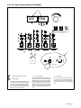
SECTION 2 – DEFINITIONS (CE Models Only)
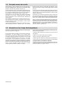
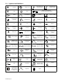
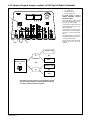
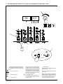
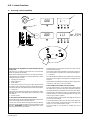
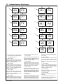
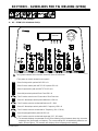
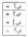
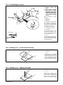
2-1. Warning Label Definitions
Warning! Watch Out! There are possible
hazards as shown by the symbols.
1 Electric shock from welding electrode
or wiring can kill.
1.1 Wear dry insulating gloves. Do not
touch electrode with bare hand. Do
not wear wet or damaged gloves.
1.2 Protect yourself from electric shock by
insulating yourself from work and
ground.
1.3 Disconnect input plug or power before
working on machine.
2 Breathing welding fumes can be
hazardous to your health.
2.1 Keep your head out of the fumes.
2.2 Use forced ventilation or local exhaust
to remove the fumes.
2.3 Use ventilating fan to remove fumes.
3 Welding sparks can cause explosion
or fire.
3.1 Keep flammables away from welding.
Do not weld near flammables.
3.2 Welding sparks can cause fires. Have
a fire extinguisher nearby, and have a
watchperson ready to use it.
3.3 Do not weld on drums or any closed
containers.
4 Arc rays can burn eyes and injure
skin.
4.1 Wear hat and safety glasses. Use ear
protection and button shirt collar. Use
welding helmet with correct shade of
filter. Wear complete body protection.
5 Become trained and read the
instructions before working on the
machine or welding.
6 Do not remove or paint over (cover)
the label.
1 1.1 1.2 1.3
2 2.1 2.2 2.3
3 3.1 3.2 3.3
4 4.1
5
6

OM-358 Page 10
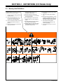
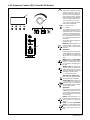
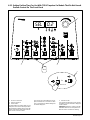
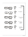
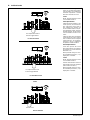
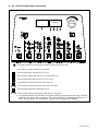
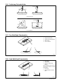
Warning! Watch Out! There are
possible hazards as shown by the
symbols.
1 Electric shock from wiring can
kill.
2 Disconnect input plug or
power before working on
machine.
3 Hazardous voltage remains
on input capacitors after
power is turned off. Do not
touch fully charged
capacitors.
4 Always wait 60 seconds after
power is turned off before
working on unit, OR
5 Check input capacitor voltage,
and be sure it is near 0 before
touching any parts.
6 When power is applied failed
parts can explode or cause
other parts to explode.
7 Flying pieces of parts can
cause injury. Always wear a
face shield when servicing
unit.
8 Always wear long sleeves and
button your collar when
servicing unit.
9 After taking proper
precautions as shown,
connect power to unit.
S-185 836
> 60 s
V
V
V
1
2
3
45
6 7
8
9
S-179 309-A
∠= <60
°
∠
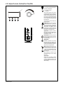
1 Warning! Watch Out! There
are possible hazards as
shown by the symbols.
2 Falling equipment can cause
injury and damage to unit.
3 Always lift and support unit
using both handles. Keep
angle of lifting device less
than 60 degrees.
4 Use a proper cart to move
unit.
5 Do not use one handle to lift
or support unit.
1/96
1
2345

OM-358 Page 11
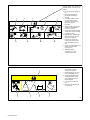
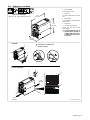
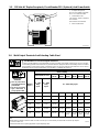
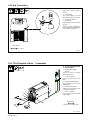
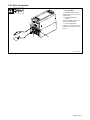
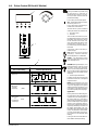
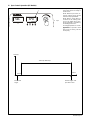
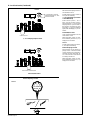
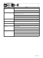
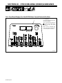
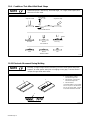
2-2. Manufacturer’s Rating Labels
Ref. ST-189 906-B
. For label location
see Section 3-4.
ST-189 968-A
Manufacture’s Rating Label For Non-CE Models
Manufacture’s Rating Label For CE Models

OM-358 Page 12
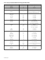
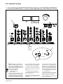
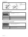
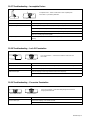
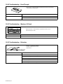
2-3. Symbols And Definitions
A
Amperes Panel–Local
Gas Tungsten Arc
Welding (GTAW)
Shielded Metal Arc
Welding (SMAW)
V
Volts Input
3 Phase Static Frequency
Converter-Transformer-Rectifier
Output Circuit Breaker Remote Lift-Arc (GTAW)
Protective Earth
(Ground)
Postflow Timer Preflow Timer
S
Seconds
On Off Positive Negative
Alternating
Current
Gas Input Gas Output
I
2
Rated Welding
Current
X
Duty Cycle Direct Current Line Connection
U
2
Conventional Load
Voltage
U
1
Primary Voltage
IP
Degree Of
Protection
I
1max
Rated Maximum
Supply Current
I
1eff
Maximum Effective
Supply Current
U
0
Rated No Load
Voltage (Average)
Pulse Background
Amperage
Initial Amperage
Increase/Decrease
Of Quantity
Normal Trigger Op-
eration (GTAW)
Two-Step Trigger
Operation (GTAW)
Four-Step Trigger
Operation (GTAW)
Percent
Hz
Hertz
Recall From
Memory
Arc Force (DIG)
Impulse Starting
(GTAW)
Final Slope Final Amperage
Pulse Percent
On Time
Initial Slope
Contactor Control
(Stick)
Pulser
TIG Weld Amps
And Peak Amps
While Pulsing
Pulse Frequency
Work Electrode
Balance % EN
Time (AC GTAW)
Process
Unit may be used
in environments
with increased
hazard of electric
shock
Sequence Adjust

OM-358 Page 13
SECTION 3 – INSTALLATION
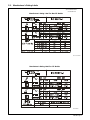
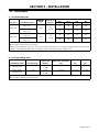
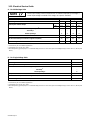
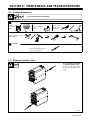
3-1. Specifications
A. For Multivoltage Units
Amperage
Maximum
Amperes Input at Rated Load Output 60 Hz
Input Power
Rated Welding Output
Amperage
Range
Open-Circuit
Voltage DC
230 V 460 V KVA KW
250 A @ 30 Volts AC, 40%
Duty Cycle
95
26.3
*.27
17.9
*.15
14.2
*.09
10.5
*.04
Three Phase
200 A @ 28 Volts DC, 40%
Duty Cycle
5–300
6–10♦
20.5
*.27
13.4
*.15
8.4
*.09
7.6
*.04
250 A @ 30 Volts AC, 40%
Duty Cycle
95
62.6
*.33
32.2
*.18
14.8
*.10
10.4
*.07
Single Phase
200 A @ 28 Volts DC, 40%
Duty Cycle
5–300
6–10♦
44
*.33
25.8
*.18
11.9
*.1
8.1
*.07
*While idling
♦Sense voltage for Stick and TIG Lift Arc present
Note: This unit is equipped with Auto-LinkR. Auto-Link is an internal inverter power source circuit that automatically links the power source to
the primary voltage being applied (230 to 460 V), without the need for manually linking primary voltage terminals.
B. For Single Voltage Units
Rated Welding Output Amperage Range
Maximum
Open-Circuit
Voltage DC
Amperes Input At Rated
Output, 50Hz - Three-Phase
400 V
KVA KW
250 A @ 30 VAC,
40% Duty Cycle
5 – 300 95 VDC
6–10♦
20.2 (0.13*) 14.0 (0.09*) 10.5 (0.04*)
200 A @ 28 VDC,
40% Duty Cycle
5 – 300 95 VDC
6–10♦
15.1 (0.13*) 10.5 (0.09*) 7.5 (0.04*)
*While idling
♦Sense voltage for Stick and TIG Lift Arc present

OM-358 Page 14
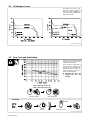
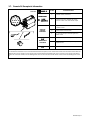
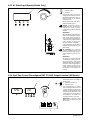
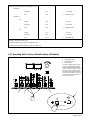
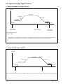
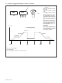
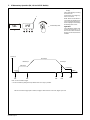
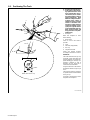
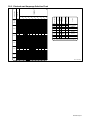
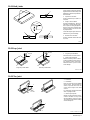
3-2. Volt-Ampere Curves
SA-185 793 / SA-186 294
Volt-ampere curves show mini-
mum and maximum voltage and
amperage output capabilities of
unit. Curves of other settings fall be-
tween curves shown.
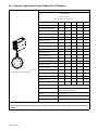
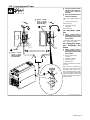
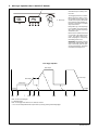
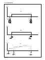
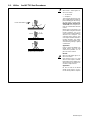
3-3. Duty Cycle and Overheating
4 Minutes Welding 6 Minutes Resting
Duty Cycle is the percentage of 10
minutes that unit can weld at rated
load without overheating.
If unit overheats, output stops, a
Help message is displayed (see
Section 5-3), and cooling fan runs.
Wait fifteen minutes for unit to cool.
Reduce amperage or voltage, or
duty cycle before welding.
Y Exceeding duty cycle can
damage unit and void
warranty.
250 A @ 40% Duty Cycle For AC
Overheating
0
15
A or V
OR
Reduce Duty Cycle
Minutes
sduty1 5/95 / SA-185 794
200 A @ 40% Duty Cycle For DC
La page est en cours de chargement...
La page est en cours de chargement...
La page est en cours de chargement...
La page est en cours de chargement...
La page est en cours de chargement...
La page est en cours de chargement...
La page est en cours de chargement...
La page est en cours de chargement...
La page est en cours de chargement...
La page est en cours de chargement...
La page est en cours de chargement...
La page est en cours de chargement...
La page est en cours de chargement...
La page est en cours de chargement...
La page est en cours de chargement...
La page est en cours de chargement...
La page est en cours de chargement...
La page est en cours de chargement...
La page est en cours de chargement...
La page est en cours de chargement...
La page est en cours de chargement...
La page est en cours de chargement...
La page est en cours de chargement...
La page est en cours de chargement...
La page est en cours de chargement...
La page est en cours de chargement...
La page est en cours de chargement...
La page est en cours de chargement...
La page est en cours de chargement...
La page est en cours de chargement...
La page est en cours de chargement...
La page est en cours de chargement...
La page est en cours de chargement...
La page est en cours de chargement...
La page est en cours de chargement...
La page est en cours de chargement...
La page est en cours de chargement...
La page est en cours de chargement...
La page est en cours de chargement...
La page est en cours de chargement...
La page est en cours de chargement...
La page est en cours de chargement...
La page est en cours de chargement...
La page est en cours de chargement...
La page est en cours de chargement...
La page est en cours de chargement...
La page est en cours de chargement...
La page est en cours de chargement...
La page est en cours de chargement...
La page est en cours de chargement...
La page est en cours de chargement...
La page est en cours de chargement...
La page est en cours de chargement...
La page est en cours de chargement...
La page est en cours de chargement...
La page est en cours de chargement...
La page est en cours de chargement...
La page est en cours de chargement...
La page est en cours de chargement...
La page est en cours de chargement...
La page est en cours de chargement...
La page est en cours de chargement...
La page est en cours de chargement...
La page est en cours de chargement...
La page est en cours de chargement...
La page est en cours de chargement...
La page est en cours de chargement...
La page est en cours de chargement...
-
 1
1
-
 2
2
-
 3
3
-
 4
4
-
 5
5
-
 6
6
-
 7
7
-
 8
8
-
 9
9
-
 10
10
-
 11
11
-
 12
12
-
 13
13
-
 14
14
-
 15
15
-
 16
16
-
 17
17
-
 18
18
-
 19
19
-
 20
20
-
 21
21
-
 22
22
-
 23
23
-
 24
24
-
 25
25
-
 26
26
-
 27
27
-
 28
28
-
 29
29
-
 30
30
-
 31
31
-
 32
32
-
 33
33
-
 34
34
-
 35
35
-
 36
36
-
 37
37
-
 38
38
-
 39
39
-
 40
40
-
 41
41
-
 42
42
-
 43
43
-
 44
44
-
 45
45
-
 46
46
-
 47
47
-
 48
48
-
 49
49
-
 50
50
-
 51
51
-
 52
52
-
 53
53
-
 54
54
-
 55
55
-
 56
56
-
 57
57
-
 58
58
-
 59
59
-
 60
60
-
 61
61
-
 62
62
-
 63
63
-
 64
64
-
 65
65
-
 66
66
-
 67
67
-
 68
68
-
 69
69
-
 70
70
-
 71
71
-
 72
72
-
 73
73
-
 74
74
-
 75
75
-
 76
76
-
 77
77
-
 78
78
-
 79
79
-
 80
80
-
 81
81
-
 82
82
-
 83
83
-
 84
84
-
 85
85
-
 86
86
-
 87
87
-
 88
88


Miller DYNASTY 300 DX Le manuel du propriétaire
- Catégorie
- Système de soudage
- Taper
- Le manuel du propriétaire
- Ce manuel convient également à
dans d''autres langues
- English: Miller DYNASTY 300 DX Owner's manual
Documents connexes
-
Miller LC286637 Le manuel du propriétaire
-
-
-
-
-
-
Miller KJ182861 Le manuel du propriétaire
-
-
-