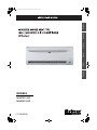
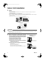
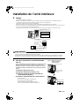
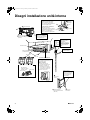
McQuay M5WMY10KR Guide d'installation
- Catégorie
- Climatiseurs split-system
- Taper
- Guide d'installation
Ce manuel convient également à

MODELS
M5WMY10KR
M5WMY15KR
EnglishDeutschFrançaisEspañolItaliano
Рóссêий
00_CV_3P257187-1A.fm Page 1 Saturday, October 31, 2009 11:21 AM

■English 1
English
Safety Precautions
• The precautions described herein are classified as WARNING and CAUTION. They both contain important
information regarding safety. Be sure to observe all precautions without fail.
• Meaning of WARNING and CAUTION notices
WARNING ............. Failure to follow these instructions properly may result in personal injury or loss of life.
CAUTION .............. Failure to observe these instructions properly may result in property damage or personal injury,
which may be serious depending on the circumstances.
• The safety marks shown in this manual have the following meanings:
• After completing installation, conduct a trial operation to check for faults and explain to the customer how to operate
the air conditioner and take care of it with the aid of the operation manual.
Be sure to follow the instructions. Be sure to establish an earth connection. Never attempt.
WARNING
• Ask your dealer or qualified personnel to carry out installation work.
Do not attempt to install the air conditioner yourself. Improper installation may result in water leakage, electric shocks or fire.
• Install the air conditioner in accordance with the instructions in this installation manual.
Improper installation may result in water leakage, electric shocks or fire.
• Be sure to use only the specified accessories and parts for installation work.
Failure to use the specified parts may result in the unit falling, water leakage, electric shocks or fire.
• Install the air conditioner on a foundation strong enough to withstand the weight of the unit.
A foundation of insufficient strength may result in the equipment falling and causing injury.
• Electrical work must be performed in accordance with relevant local and national regulations and with instructions
in this installation manual. Be sure to use a dedicated power supply circuit only.
Insufficiency of power circuit capacity and improper workmanship may result in electric shocks or fire.
• Use a cable of suitable length.
Do not use tapped wires or an extension lead, as this may cause overheating, electric shocks or fire.
• Make sure that all wiring is secured, the specified wires are used, and that there is no strain on the terminal
connections or wires.
Improper connections or securing of wires may result in abnormal heat build-up or fire.
• When wiring the power supply and connecting the wiring between the indoor and outdoor units, position the wires
so that the control box lid can be securely fastened.
Improper positioning of the control box lid may result in electric shocks, fire or over heating terminals.
• If refrigerant gas leaks during installation, ventilate the area immediately.
Toxic gas may be produced if the refrigerant comes into contact with fire.
• After completing installation, check for refrigerant gas leakage.
Toxic gas may be produced if the refrigerant gas leaks into the room and comes into contact with a source of fire, such as a fan
heater, stove or cooker.
• When installing or relocating the air conditioner, be sure to bleed the refrigerant circuit to ensure it is free of air, and
use only the specified refrigerant (R410A).
The presence of air or other foreign matter in the refrigerant circuit causes abnormal pressure rise, which may result in equipment damage and
even injury.
• During installation, attach the refrigerant piping securely before running the compressor.
If the compressor is not attached and the stop valve is open when the compressor is run, air will be sucked in, causing abnormal pressure in
the refrigeration cycle, which may result in equipment damage and even injury.
• During pump-down, stop the compressor before removing the refrigerant piping.
If the compressor is still running and the stop valve is open during pump-down, air will be sucked in when the refrigerant piping is removed,
causing abnormal pressure in the refrigeration cycle, which may result in equipment damage and even injury.
• Be sure to earth the air conditioner.
Do not earth the unit to a utility pipe, lightning conductor or telephone earth lead. Imperfect earthing may result in electric shocks.
• Be sure to install an earth leakage breaker.
Failure to install an earth leakage breaker may result in electric shocks or fire.
CAUTION
• Do not install the air conditioner at any place where there is a danger of flammable gas leakage.
In the event of a gas leakage, build-up of gas near the air conditioner may cause a fire to break out.
• While following the instructions in this installation manual, install drain piping to ensure proper drainage and
insulate piping to prevent condensation.
Improper drain piping may result in indoor water leakage and property damage.
• Tighten the flare nut according to the specified method such as with a torque wrench.
If the flare nut is too tight, it may crack after prolonged use, causing refrigerant leakage.
01_EN_3P257187-1A.fm Page 1 Thursday, November 12, 2009 12:01 PM

2 ■English
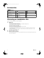
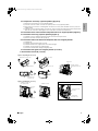
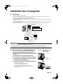
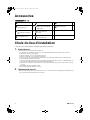
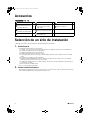
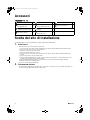
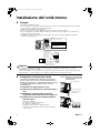
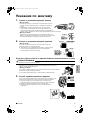
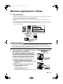
Accessories
– ,
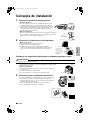
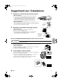
Choosing an Installation Site
• Before choosing the installation site, obtain user approval.
1.
Indoor unit
• The indoor unit should be sited in a place where:
1) the restrictions on installation specified in the indoor unit installation drawings are met,
2) both air inlet and air outlet have clear paths met,
3) the unit is not in the path of direct sunlight,
4) the unit is away from the source of heat or steam,
5) there is no source of machine oil vapour (this may shorten indoor unit life),
6) cool (warm) air is circulated throughout the room,
7) the unit is away from electronic ignition type fluorescent lamps (inverter or rapid start type) as they may shorten the
remote controller range,
8) the unit is at least 1m away from any television or radio set (unit may cause interference with the picture or sound),
9) install at the recommended height (1.8m),
10) no laundry equipment is located.
2.
Wireless remote controller
• Turn on all the fluorescent lamps in the room, if any, and find the site where remote controller signals are properly received
by the indoor unit (within 7m).
Mounting plate
1
Remote controller holder
1
Operation manual
1
Mounting plate fixing screw
(M4 × 25L)
6
Fixing screw for remote
controller holder (M3 × 20L)
2
Installation manual
1
Titanium apatite photocatalytic
air-purifying filter
2
Dry battery AAA. LR03
(alkaline)
2
Wireless remote controller
1
Indoor unit fixing screw
(M4 × 12L)
2
Indoor unit
A
K
A
E
J
B
F
K
C
G
D
H
01_EN_3P257187-1A.fm Page 2 Thursday, November 12, 2009 12:01 PM

■English 3
English
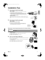
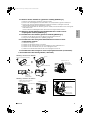
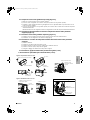
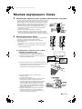
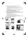
Installation Tips
1.
Removing and installing front panel
•Removal method
1) Place your fingers in the indentations on the main unit (one each on the
left and right sides), and open the panel until it stops.
2) Continue to open the front panel further while sliding the panel to the right
and pulling it toward you in order to disengage the rotating shaft on the
left side. To disengage the rotating shaft on the right side, slide the panel
to the left while pulling it toward you.
• Installation method
Align the tabs of the front panel with the grooves, and push all the way in. Then
close slowly. Push the center of the lower surface of the panel firmly to engage the
tabs.
2.
Removing and installing front grille
•Removal method
1) Remove front panel to remove the air filter.
2) Remove the screws (2) from the front grille.
3) In front of the {{{ mark of the front grille, there are 3 upper hooks.
Lightly pull the front grille toward you with one hand, and push down on
the hooks with the fingers of your other hand.
When there is no work space because the unit is close to ceiling
CAUTION
• Be sure to wear protection gloves.
Place both hands under the center of the front grille, and while pushing up, pull it toward you.
• Installation method
1) Install the front grille and firmly engage the upper hooks (3 locations).
2) Install 2 screws of the front grille.
3) Install the air filter and then mount the front panel.
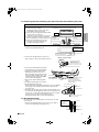
3.
How to set the different addresses
When two indoor units are installed in one room, the two wireless remote controllers
can be set for different addresses.
1) In the same way as when connecting to an HA system, remove the metal plate
electrical wiring cover.
2) Cut the address jumper (JA) on the printed circuit board.
3) Cut the address jumper (J4) in the remote controller.
Indentations on
the main unit
Push the rotating
shaft of the front
panel into the groove.
Rotating shaft
mark area
(3 locations)
Upper hook
Lightly pull the front
grille toward you with
one hand, and push
down on the hooks with
the fingers of your other
hand. (3 locations)
Push
down.
Upper hook
1) Push up.
2) Pull toward you.
ADDRESS
EXIST
CUT
1
2
JA
JA
J4
ADDRESS
EXIST
CUT
1
2
J4
01_EN_3P257187-1A.fm Page 3 Thursday, November 12, 2009 12:01 PM

4 ■English
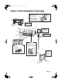
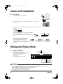
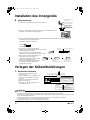
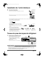
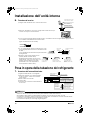
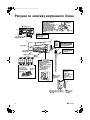
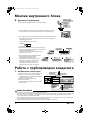
Indoor Unit Installation Drawings
A
Screws
(M4 × 16L)
Service lid
Opening service lid
Service lid is opening/closing type.
Opening method
1) Remove the service lid screws.
2) Pull out the service lid diagonally
down in the direction of the arrow.
3) Pull down.
Wrap the insulation pipe with
the finishing tape from bottom
to top.
Cut thermal insulation
pipe to an appropriate
length and wrap it with
tape, making sure that no
gap is left in the insulation
pipe’s cut line.
Caulk
pipe hole
gap
with putty.
Mounting
plate
Clip
Mark (rear side)
Bottom frame
Front grille
How to attach the indoor unit
Hook the claws of the bottom frame
to the mounting plate.
If the claws are difficult to hook,
remove the front grille.
How to remove the indoor unit
Push up the marked area (at the
lower part of the front grille) to
release the claws. If it is difficult to
release, remove the front grille.
The mounting plate
should be installed on a
wall which can support the
weight of the indoor unit.
30mm or more from ceiling
Front panel
50mm or more from walls
(on both sides)
Air filters
Titanium apatite photocatalytic
air-purifying filter (2)
A Mounting plate
B Mounting plate
fixing screw
(M4 × 25L)
Air filter
Titanium apatite
photocatalytic
air-purifying filter
Filter frame
Ta b
C
F Fixing screw for remote
controller holder
(M3 × 20L)
D
Wireless remote
controller
E
Remote
controller holder
Before screwing the
remote controller
holder to the wall,
make sure that
control signals are
properly received by
indoor unit.
01_EN_3P257187-1A.fm Page 4 Thursday, November 12, 2009 12:01 PM

■English 5
English
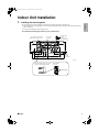
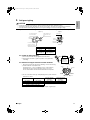
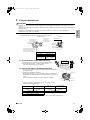
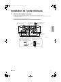
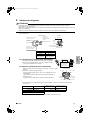
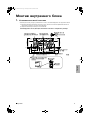
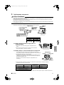
Indoor Unit Installation
1.
Installing the mounting plate
• The mounting plate should be installed on a wall which can support the weight of the indoor unit.
1) Temporarily secure the mounting plate to the wall, make sure that the panel is completely level, and mark the boring
points on the wall.
2) Secure the mounting plate to the wall with screws.
Recommended mounting plate retention spots and dimensions
770
Use tape measure
as shown.
Position the end of
a tape measure at .
Keep here the piece cut out
from the unit for piping
unit: mm
Gas pipe end
* The removed pipe port cover can be
kept in the mounting plate pocket.
Removed pipe
port cover
A
Mounting plate
Through-
the-wall
hole φ65mm
Recommended mounting plate
retention spots (5 spots in all)
Place a leveler
on raised tab.
41.3
41.3
241.7
54
330.5
241.7
160
54.5
50160
101120.5
331
203 247
Drain hose
position
Liquid pipe end
01_EN_3P257187-1A.fm Page 5 Thursday, November 12, 2009 12:01 PM

6 ■English
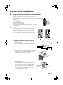
Indoor Unit Installation
2.
Boring a wall hole and installing wall embedded pipe
• For walls containing metal frame or metal board, be sure to use a wall
embedded pipe and wall cover in the feed-through hole to prevent possible
heat, electrical shock, or fire.
• Be sure to caulk the gaps around the pipes with caulking material to prevent
water leakage.
1) Bore a feed-through hole of 65mm in the wall so it has a down slope
toward the outside.
2) Insert a wall pipe into the hole.
3) Insert a wall cover into wall pipe.
4) After completing refrigerant piping, wiring, and drain piping, caulk pipe hole
gap with putty.
3.
Installing indoor unit
• In the case of bending or curing refrigerant pipes, keep the following
precautions in mind.
Abnormal sound may be generated if improper work is conducted.
1) Do not strongly press the refrigerant pipes onto the bottom frame.
2) Do not strongly press the refrigerant pipes on the front grille, either.
3-1.
Right-side, right-back, or right-bottom piping
1) Attach the drain hose to the underside of the refrigerant pipes with
an adhesive vinyl tape.
2) Wrap the refrigerant pipes and drain hose together with an
insulation tape.
3) Pass the drain hose and refrigerant pipes through the wall hole, then
set the indoor unit on the mounting plate hooks by using the
markings at the top of the indoor unit as a guide.
4) Open the front panel, then open the service lid.
(Refer to installation tips.)
5)
Pass the inter-unit wiring from the outdoor unit through the feed-
through wall hole and then through the back of the indoor unit.
Pull them through the front side. Bend the ends of tie wires
upward for easier work in advance. (If the inter-unit wiring ends
are to be stripped first, bundle wire ends with adhesive tape.)
6) Press the bottom frame of the indoor unit with both hands to set
it on the mounting plate hooks. Make sure the wires do not
catch on the edge of the indoor unit.
Inside Outside
Caulking
Wall embedded pipe
(field supply)
Wall hole cover
(field supply)
Wall embedded pipe
(field supply)
φ65
1)
2)
Right-bottom
piping
Right-back piping
Bind coolant pipe
and drain hose
together with
insulating tape.
Remove pipe port cover
here for right-side piping.
Remove pipe port cover
here for right-bottom piping.
Mounting plate
A
Wire guide
When stripping the
ends of inter-unit wiring
in advance, bind right ends
of wires with insulating tape.
Hang indoor unit’s hook here.
Inter-unit wiring
Mounting plate
A
01_EN_3P257187-1A.fm Page 6 Thursday, November 12, 2009 12:01 PM

■English 7
English
3-2. Left-side, left-back, or left-bottom piping
1) Attach the drain hose to the underside of the refrigerant pipes
with adhesive vinyl tape.
2) Be sure to connect the drain hose to the drain port in place of a
drain plug.
3) Shape the refrigerant pipe along the pipe
path marking on the mounting plate.
4) Pass drain hose and refrigerant pipes
through the wall hole, then set the indoor
unit on mounting plate hooks, using the
markings at the top of indoor unit as a
guide.
5) Pull in the inter-unit wiring.
6) Connect the inter-unit piping.
7) Wrap the refrigerant pipes and drain hose together with insulation tape as
right figure, in case of setting the drain hose through the back of the indoor
unit.
8) While exercising care so that the inter-unit wiring do not catch indoor unit,
press the bottom edge of indoor unit with both hands until it is firmly
caught by the mounting plate hooks. Secure indoor unit to the mounting
plate with indoor unit fixing screws (M4 × 12L).
3-3. Wall embedded piping
Follow the instructions given under left-side, left-back, or left-bottom piping.
1) Insert the drain hose to this depth so it won’t be pulled out of the drain
pipe.
• Replacing onto the left side
1) Remove the insulation fixing screws on the right
to remove the drain hose.
2) Reattach the insulation fixing screw on the right
as it was.
* (Forgetting to attach this may cause water
leakages.)
3) Remove the drain plug on the left side and
attach it to the right side.
4) Insert the drain hose and tighten with included
indoor unit fixing screw.
How to replace the drain plug and drain hose
Drain hose attachment position
* The drain hose is on the back of the unit.
Front side of unit
Attachment on the right side (factory default)
Attachment on the left side
Drain hose Drain hose
Indoor unit
fixing screw
Insulation
fixing screw
Right sideLeft side
Remove pipe port cover here for left-bottom piping.
Remove pipe
port cover
here for left-
side piping.
Left-bottom piping
Left-side
piping
Left-back
piping
How to set drain plug.
No gap.
Do not apply lubricating
oil (refrigeration oil)
when inserting.
Application of causes
deterioration and drain
leakage of the plug.
Insert a hexagonal wrench (4mm).
Drain
hose
Caulk this hole
with putty or
caulking material.
Bind with vinyl
tape.
A
Mounting plate
Wrap insulating tape around the
bent portion of refrigerant pipe.
Overlap at least half the width of
the tape with each turn.
Refrigerant
pipes
Drain hose
Bottom frame
H Indoor unit fixing screw
M4 × 12L (2 point)
Mounting
plate
A
Inter-unit wiring
Inner wall
Vinyl chloride
drain pipe
(VP-30)
Drain hose50mm
or more
Insert drain hose
to this depth so
it won’t be pulled
out of drain pipe.
Outer wall
01_EN_3P257187-1A.fm Page 7 Thursday, November 12, 2009 12:01 PM

8 ■English
Indoor Unit Installation
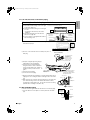
4.
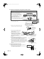
Wiring
1) Strip wire ends (15mm).
2) Match wire colours with terminal numbers on indoor and outdoor unit’s terminal blocks and firmly screw wires to the
corresponding terminals.
3) Connect the earth wires to the corresponding terminals.
4) Pull wires to make sure that they are securely latched up, then retain wires with wire retainer.
5)
In case of connecting to an adapter system. Run the remote control cable and attach the S21. (Refer to 5. When connecting to a
wired remote controller.)
6) Shape the wires so that the service lid fits securely, then close service lid.
WARNING
• Do not use tapped wires, stranded wires, extension cords, or starburst connections, as they may cause overheating, electrical
shock, or fire.
• Do not use locally purchased electrical parts inside the product. (Do not branch the power for the drain pump, etc., from the
terminal block.) Doing so may cause electric shock or fire.
5.
When connecting to a wired remote controller
* If work space is available on the right side of the indoor unit, the work
can be performed with the electrical component box attached. Omit the
steps involved with removing and installing the electrical component
box in order to perform the work more efficiently.
5-1. Remove the front grille (2 screws).
5-2. Remove the service lid (1 screw).
5-3. Remove the cover from the indoor unit electrical
component box [Figure 1].
* 5-4. Remove the indoor unit electrical component box.
1) Remove the flap.
2) Disconnect the communication wiring.
3) Disconnect the connector (S200).
4) Remove the thermistor from the heat exchanger.
5) Remove the electrical component box installation screw (1 screw).
123
Terminal block
Electrical component box
Wire retainer
Use the specified
wire type.
Shape wires so that the
service lid will fit securely.
Firmly secure wire retainer so that
wires sustain no external stress.
1
2
3
123 LN
Use 2.0mm diameter wires.
H05RN
Firmly fix the wires with
the terminal screws.
Outdoor unit
Indoor
unit
Firmly fix the wires with
the terminal screws.
Disengage the tab.
Figure 1: Removing the cover from
the indoor unit electrical
component box
Disengage the tab.
Cover of the indoor unit
electrical component box
01_EN_3P257187-1A.fm Page 8 Thursday, November 12, 2009 12:01 PM

■English 9
English
5-5. Prepare the accessory (separate product) [Figure 2].
1) Remove the cover from the accessory (separate product).
2) Insert the connection cord into connector “S21” (white) in the accessory (separate product).
3) Route each of the connection cords through the cut-outs in the accessory, then reinstall the accessory cover in its
original position.
4) Insert the accessory (separate product) connector into connector “S403” in the indoor unit electrical component box.
Then route the connection cord through the cut-out in the indoor unit electrical component box.
5-6. Install the cover of the electrical component box in its original position [Figure 3].
5-7. Install the accessory (separate product) [Figure 3].
1) Install the accessory (separate product) into the indoor unit electrical component box.
2) Route the connection cord as shown in [Figure 3].
* 5-8. Install the indoor unit electrical component box in its original position.
1) Install the flap.
2) Install the electrical component box (1 screw).
3) Install the thermistor in its original position on the heat exchanger.
4) Install the connector (S200) in its original position.
5) Connect the communication wiring in its original position.
5-9. Install the front grille in its original position (2 screws).
5-10. Install the service lid (1 screw).
Disengage the tab.
Remove the accessory cover.
Route each of the
connection cords.
Insert “S403”.
Route the connection
cords through the cut-outs.
“S21”
Accessory
Accessory
Accessory cover
Accessory
cover
Install the accessory.
Install the accessory cover
in its original position.
Cut-out for the “S403”
connection
Cut-out for the
connection cord
Figure 2: Preparing the accessory
Figure 3: Installing the accessory
Cut-outs for the connection cords
01_EN_3P257187-1A.fm Page 9 Thursday, November 12, 2009 12:01 PM

10 ■English
Indoor Unit Installation
6.
Drain piping
1) Connect the drain hose, as described right.
2) Remove the air filters and pour some water into the drain pan to check the water
flows smoothly.
3) If drain hose extension or embedded drain piping is required, use appropriate parts that match the hose front end.
[Figure of hose front end]
4) When extending the drain hose, use a commercially available
extension hose with an inner diameter of 16mm.
Be sure to thermally insulate the indoor section of the extension
hose.
5) When connecting a rigid polyvinyl chloride pipe
(nominal diameter 13mm) directly to the drain
hose attached to the indoor unit as with
embedded piping work, use any commercially
available drain socket (nominal diameter 13mm)
as a joint.
Refrigerant Piping Work
1.
Flaring the pipe end
1) Cut the pipe end with a pipe cutter.
2) Remove burrs with the cut surface facing downward
so that the chips do not enter the pipe.
3) Put the flare nut on the pipe.
4) Flare the pipe.
5) Check that the flaring is properly made.
WARNING
• Do not use mineral oil on flared part.
• Prevent mineral oil from getting into the system as this would reduce the lifetime of the units.
• Never use piping which has been used for previous installations. Only use parts which are delivered with the unit.
• Do never install a drier to this R410A unit in order to guarantee its lifetime.
• The drying material may dissolve and damage the system.
• Incomplete flaring may cause refrigerant gas leakage.
The drain hose should
be inclined downward.
No trap is permitted.
Do not put the end
of the hose in water.
φ18φ16
φ16
The drain hose provided
to indoor unit.
Indoor unit
drain hose
φ16
Extension drain hose
Heat insulation tube
(field supply)
Commercially available drain
socket
(nominal diameter 13mm)
Commercially available rigid
polyvinyl chloride pipe
(nominal diameter 13mm)
The drain hose provided
to indoor unit.
φ18
Set exactly at the position shown below.
A
Flaring
Die
A 0-0.5mm
Clutch-type
Flare tool for R410A
1.0-1.5mm
Clutch-type (Rigid-type)
1.5-2.0mm
Wing-nut type (Imperial-type)
Conventional flare tool
(Cut exactly at
right angles.) Remove burrs.
Check
Flare’s inner
surface must
be flaw-free.
The pipe end must
be evenly flared in
a perfect circle.
Make sure that the
flare nut is fitted.
01_EN_3P257187-1A.fm Page 10 Thursday, November 12, 2009 12:01 PM

■English 11
English
2.
Refrigerant piping
CAUTION
• Use the flare nut fixed to the main unit. (To prevent cracking of the flare nut by aged deterioration.)
• To prevent gas leakage, apply refrigeration oil only to the inner surface of the flare. (Use refrigeration oil for R410A.)
• Use torque wrenches when tightening the flare nuts to prevent damage to the flare nuts and gas leakage.
Align the centres of both flares and tighten the flare nuts 3 or 4 turns by hand. Then tighten them fully with the torque wrenches.
2-1.
Caution on piping handling
1) Protect the open end of the pipe against dust and moisture.
2) All pipe bends should be as gentle as possible. Use a pipe bender
for bending.
2-2.
Selection of copper and heat insulation materials
• When using commercial copper pipes and fittings, observe the following:
1) Insulation material: Polyethylene foam
Heat transfer rate: 0.041 to 0.052W/mK (0.035 to 0.045 kcal/mh°C)
Refrigerant gas pipe’s surface temperature reaches 110°C max.
Choose heat insulation materials that will withstand this temperature.
2) Be sure to insulate both the gas and liquid piping and to provide insulation
dimensions as below.
3) Use separate thermal insulation pipes for gas and liquid refrigerant pipes.
Gas side Liquid side
Gas pipe thermal
insulation
Liquid pipe thermal
insulation
O.D. 9.5mm O.D. 6.4mm I.D. 12-15mm I.D. 8-10mm
Minimum bend radius Thickness 10mm Min.
30mm or more
Thickness 0.8mm (C1220T-O)
Do not apply refrigeration
oil to the outer surface.
Flare nut
Apply refrigeration oil to
the inner surface of the
flare.
Do not apply refrigeration
oil to the flare nut avoid
tightening with over torque.
[Apply oil]
Torque wrench
Piping union
Flare nut
Spanner
[Tighten]
Flare nut tightening torque
Gas side Liquid side
3/8 inch 1/4 inch
32.7-39.9N
m
(330-407kgf
cm)
14.2-17.2N
m
(144-175kgf
cm)
Wall
If no flare cap is
available, cover
the flare mouth
with tape to keep
dirt or water out.
Be sure to
place a cap.
Rain
Gas pipe
Liquid pipe
Gas pipe
insulation
Liquid pipe
insulation
Finishing tape
Drain hose
Inter-unit wiring
01_EN_3P257187-1A.fm Page 11 Thursday, November 12, 2009 12:01 PM

12 ■English
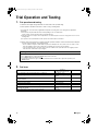
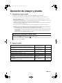
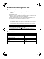
Trial Operation and Testing
1.
Trial operation and testing
1-1 Measure the supply voltage and make sure that it falls in the specified range.
1-2 Trial operation should be carried out in either cooling or heating mode.
• In cooling mode, select the lowest programmable temperature; in heating mode, select the highest programmable
temperature.
1) Trial operation may be disabled in either mode depending on the room temperature.
Use the remote controller for trial operation as described below.
2) After trial operation is complete, set the temperature to a normal level (26°C to 28°C in cooling mode, 20°C to 24°C in
heating mode).
3) For protection, the system disables restart operation for 3 minutes after it is turned off.
1-3 Carry out the test operation in accordance with the operation manual to ensure that all functions and parts,
such as louver movement, are working properly.
• The air conditioner requires a small amount of power in its standby mode. If the system is not to be used for some
time after installation, shut off the circuit breaker to eliminate unnecessary power consumption.
• If the circuit breaker trips to shut off the power to the air conditioner, the system will restore the original operation
mode when the circuit breaker is opened again.
2.
Test items
Test items
Symptom
(diagnostic display on RC)
Check
Indoor and outdoor units are installed properly on solid bases. Fall, vibration, noise
No refrigerant gas leaks.
Incomplete cooling/heating
function
Refrigerant gas and liquid pipes and indoor drain hose extension are
thermally insulated.
Water leakage
Draining line is properly installed. Water leakage
System is properly earthed. Electrical leakage
The specified wires are used for inter-unit wiring connections. Inoperative or burn damage
Indoor or outdoor unit’s air inlet or air outlet has clear path of air.
Stop valves are opened.
Incomplete cooling/heating
function
Indoor unit properly receives remote control commands. Inoperative
1) Press “ON/OFF” button to turn on the system.
2) Press “TEMP” button (2 locations) and “MODE” button at the same time.
3) Press “MODE” button twice and select “ ”.
4) Trial operation terminates in approx. 30 minutes and switches into normal mode. To quit a trial operation, press
“ON/OFF” button.
Trial operation from remote controller
01_EN_3P257187-1A.fm Page 12 Thursday, November 12, 2009 12:01 PM

■Deutsch 1
Deutsch
Sicherheitshinweise
• Die hier beschriebenen Warnhinweise sind mit WARNUNG und ACHTUNG gekennzeichnet. Sie enthalten wichtige
Informationen bezüglich der Sicherheit. Beachten Sie unbedingt alle Warnhinweise.
• Bedeutung der Hinweise WARNUNG und ACHTUNG
WARNUNG
...........Bei Nichteinhaltung von WARNUNG besteht die Wahrscheinlichkeit ernsthafter Konse-
quenzen wie Tod oder schwere Körperverletzung.
ACHTUNG
............Werden die ACHTUNG nicht beachtet, kann dies gefährliche Konsequenzen nach sich ziehen.
• Die in dieser Anleitung enthaltenen Sicherheitssymbole haben die folgenden Bedeutungen:
• Führen Sie nach Abschluss der Installation einen Probelauf durch, um etwaige Fehler festzustellen, und erklären Sie
dem Kunden anhand der Bedienungsanleitung, wie die Klimaanlage zu bedienen und zu pflegen ist.
Folgen Sie den Anweisungen. Stellen Sie unbedingt einen Erdanschluß her.
Versuchen Sie dies niemals.
WARNUNG
• Beauftragen Sie Ihren Händler oder qualifiziertes Personal mit der Installation der Anlage.
Versuchen Sie nicht, die Klimaanlage selbst zu installieren. Eine unsachgemäße Installation kann zu Wasserlecks, elektrischen Schlägen oder Brand führen.
• Installieren Sie die Klimaanlage gemäß den Anweisungen in dieser Installationsanleitung.
Eine unsachgemäße Installation kann zu Wasserlecks, elektrischen Schlägen oder Brand führen.
• Verwenden Sie nur vorgeschriebenes Zubehör und Teile für die Installationsarbeiten.
Bei Verwendung ungeeigneter Teile besteht die Gefahr, dass das Gerät herunterfällt oder ein Wasserleck, elektrischer Schlag oder Brand verursacht wird.
• Installieren Sie die Klimaanlage auf einem Fundament, das stark genug für das Gewicht der Anlage ist.
Ein Fundament von unzureichender Tragfähigkeit kann zu Herunterfallen und Unfällen mit Verletzungen führen.
• Elektroarbeiten müssen gemäß den relevanten lokalen und nationalen Bestimmungen und den Anweisungen in
dieser Installationsanleitung durchgeführt werden. Verwenden Sie nur einen festgeschalteten Stromkreis.
Unzureichende Stromkreiskapazität und unsachgemäße Arbeitsausführung können zu elektrischen Schlägen oder Brand führen.
• Verwenden Sie ein Kabel von geeigneter Länge.
Verwenden Sie keine Abzweigleitungen oder Verlängerungskabel, weil diese zu Überhitzen, elektrischen Schlägen oder Brand führen können.
• Vergewissern Sie sich, dass die gesamte Verkabelung sicher befestigt ist, die vorgeschriebenen Kabeltypen
verwendet werden und die Klemmenanschlüsse oder Kabel keiner Belastung ausgesetzt sind.
Falsche Anschlüsse oder Befestigung der Kabel können zu abnormaler Wärmebildung oder einem Brand führen.
• Bei der Verkabelung der Stromversorgung und der Verbindung der Kabel zwischen Innen- und Außengerät sind
die Kabel so zu verlegen, dass der Schaltkastendeckel sicher befestigt werden kann.
Falsche Anbringung des Schaltkastendeckels kann zu elektrischen Schlägen, Brand oder Überhitzen der Klemmen führen.
• Falls Kältemittelgas während der Installation entweicht, ist der Bereich sofort zu belüften.
Giftiges Gas kann entstehen, falls das Kältemittel mit Feuer in Berührung kommt.
• Überprüfen Sie die Anlage nach der Installation auf Kältemittelgaslecks.
Giftiges Gas kann erzeugt werden, falls
Kältemittelgas in den Raum entweicht und mit einer Feuerquelle wie z. B. einem Heizkörper, Ofen oder Herd in Berührung kommt.
• Wenn Sie die Klimaanlage installieren oder versetzen, entlüften Sie unbedingt den Kältemittelkreis, um
sicherzugehen, dass er frei von Luft ist, und verwenden Sie nur das vorgeschriebene Kältemittel (R410A).
Das Vorhandensein von Luft oder anderen Fremdstoffen im Kältemittelkreis verursacht einen abnormalen Druckanstieg, der zu einer
Beschädigung der Anlage oder gar zu Verletzungen führen kann.
•
Schließen Sie während der Installation die Kältemittel-Rohrleitungen einwandfrei an, bevor Sie den Kompressor in Betrieb nehmen
.
Falls der Kompressor nicht einwandfrei angeschlossen und das Absperrventil während des Kompressorbetriebs offen ist, wird Luft angesaugt,
wodurch ein abnormaler Druck im Kühlkreislauf verursacht wird, was zu einer Beschädigung der Anlage oder gar zu Verletzungen führen kann.
• Stellen Sie den Kompressor während des Pumpenstillstands ab, bevor Sie die Kältemittel-Rohrleitungen abtrennen.
Falls der Kompressor noch läuft und das Absperrventil während des Pumpenstillstands offen ist, wird beim Abtrennen der Kältemittel-
Rohrleitungen Luft angesaugt, wodurch ein abnormaler Druck im Kühlkreislauf verursacht wird, was zu einer Beschädigung der Anlage oder
gar zu Verletzungen führen kann.
• Die Klimaanlage muss unbedingt geerdet werden.
Erden Sie das Gerät nicht an einer Gas- oder Wasserleitung, einem
Blitzableiter oder der Erdleitung eines Telefons. Falsche Erdung kann zu elektrischen Schlägen führen.
• Installieren Sie unbedingt einen Fehlerstrom-Schutzschalter.
Wird kein Fehlerstrom-Schutzschalter installiert, kann es zu elektrischen Schlägen oder einem Brand kommen.
ACHTUNG
•
Installieren Sie die Klimaanlage nicht an Orten, wo die Gefahr eines Lecks von brennbaren Gasen besteht.
Im Falle eines Gaslecks kann die Ansammlung von Gas in der Nähe der Klimaanlage zu einem Brand führen.
• Installieren Sie die Ablaufleitungen nach den Anweisungen in dieser Installationsanleitung, um einwandfreies
Ablaufen zu gewährleisten, und isolieren Sie die Leitungen, um Kondensation zu verhüten.
Falsche Verlegung der Ablaufleitungen kann zu Wasserlecks und Sachschäden im Innenraum führen.
• Ziehen Sie die Bördelmutter nach der vorgeschriebenen Methode an, z. B. mit einem Drehmomentschlüssel.
Falls die Bördelmutter zu fest sitzt, kann sie nach längerem Gebrauch reißen, wodurch ein Kältemittelleck verursacht wird.
02_DE_3P257187-1A.fm Page 1 Thursday, November 12, 2009 12:05 PM

2 ■Deutsch
Zubehör
– ,
Auswahl des Installationsorts
• Holen Sie vor der Wahl des Installationsorts die Zustimmung des Benutzers ein.
1.
Innengerät
• Das Innengerät sollte an einem Ort installiert werden, der den folgenden Bedingungen entspricht.
1) Die Bedingungen in der Installationszeichnung für das Innengerät werden erfüllt.
2) Lufteinlass und Luftauslass sind nicht behindert.
3) Das Gerät ist nicht direkter Sonneneinstrahlung ausgesetzt.
4) Das Gerät befindet sich nicht in der Nähe von Wärme- oder Dampfquellen.
5) Es ist keine Quelle von Maschinenöldünsten vorhanden. (Dies kann die Lebensdauer des Innengeräts verkürzen.)
6) Kühle (warme) Luft wird im Raum umgewälzt.
7) Das Gerät befindet sich nicht in der Nähe von Leuchtstofflampen mit elektronischer Zündung (Inverter oder
Schnellstart), da hierdurch die Reichweite der Fernbedienung verringert werden kann.
8) Das Gerät befindet sich in mindestens 1m Entfernung von einem Fernseh- oder Radiogerät (die Einheit kann Bild- oder
Tonstörungen verursachen),
9) Installation in der empfohlenen Höhe (1,8m),
10) Keine Wäschereiausrüstung ist vorhanden.
2.
Drahtlose Fernbedienung
• Schalten Sie alle Leuchtstofflampen im Zimmer an, soweit vorhanden, und suchen Sie die Stelle, an der die Signale der
Fernbedienung wie vorgesehen vom Innengerät empfangen werden (innerhalb von 7m).
Montageplatte
1
Fernbedienungshalter
1
Bedienungsanleitung
1
Montageplatten-
Befestigungsschraube
(M4 × 25L)
6
Befestigungsschrauben für
den Fernbedienungshalter
(M3 × 20L)
2
Installationsanleitung
1
Fotokatalytischer Titan-Apatit-
Luftreinigungsfilter
2
Trockenbatterie AAA. LR03
(Alkali)
2
Drahtlose Fernbedienung
1
Innengerät-Befestigungsschraube
(M4 × 12L)
2
Innengerät
A
K
A
E
J
B
F
K
C
G
D
H
02_DE_3P257187-1A.fm Page 2 Thursday, November 12, 2009 12:05 PM

■Deutsch 3
Deutsch
Installationstipps
1.
Abnehmen und Anbringen der Frontplatte
• Ausbaumethode
1)
Platzieren Sie Ihre Finger in die Vertiefungen des Hauptgeräts (je eine auf der
linken und rechten Seite), und öffnen Sie die Frontplatte bis zum Anschlag.
2) Öffnen Sie die Frontplatte weiter, während Sie die Platte nach rechts
schieben und auf sich zu ziehen, um die Drehachse auf der linken Seite
zu lösen. Um die Drehachse auf der rechten Seite zu lösen, schieben Sie
die Platte nach links, während Sie sie auf sich zu ziehen.
• Einbaumethode
Richten Sie die Nasen der Frontplatte auf die Nuten aus, und drücken Sie diese
vollständig hinein. Danach langsam schließen. Drücken Sie die Mitte der unteren
Fläche der Frontplatte fest ein, damit die Nasen einrasten.
2.
Abnehmen und Anbringen des Frontgrills
• Ausbaumethode
1) Entfernen Sie zum Ausbauen des Luftfilters die Frontplatte.
2) Die Schrauben (2) vom Frontgrill entfernen.
3) Vor der Markierung {{{ am Frontgrill befinden sich 3 obere Haken.
Ziehen Sie den Frontgrill mit einer Hand leicht zu sich heran, und
drücken Sie mit den Fingern Ihrer anderen Hand die Haken hinein.
Wenn kein Platz zum Arbeiten vorhanden ist, weil sich das Gerät nahe an der Decke befindet
ACHTUNG
• Tragen Sie unbedingt Schutzhandschuhe.
Legen Sie beide Hände unter die Mitte des Frontgrills, und ziehen Sie ihn zu sich heran,
während Sie ihn gleichzeitig nach oben drücken.
• Einbaumethode
1) Bringen Sie den Frontgrill an, und rasten Sie die oberen Haken fest ein (3 Stellen).
2) Schrauben Sie die 2 Schrauben des Frontgrills fest.
3) Bauen Sie den Luftfilter ein, und bringen Sie dann die Frontplatte an.
3.
Einrichten der verschiedenen Adressen
Wenn zwei Innengeräte in einem Raum installiert sind, können die beiden
drahtlosen Fernbedienungen auf unterschiedliche Adressen eingestellt werden.
1) Nehmen Sie die Metallabdeckung des elektrischen Anschlusskastens ab,
wie beim Anschluss an ein HA-System.
2) Ziehen Sie den Adressen-Jumper (JA) auf der Platine ab.
3) Ziehen Sie den Adressen-Jumper (J4) in der Fernbedienung ab.
Vertiefungen
am Hauptgerät
Drücken Sie die
Drehachse der
Frontplatte in die Nut
ein.
Drehachse
Bereich der Markierung
(3 Stellen)
Oberer Haken
Nach unten drücken.
Ziehen Sie den Frontgrill
mit einer Hand leicht zu
sich heran, und drücken
Sie mit den Fingern Ihrer
anderen Hand die Haken
hinein. (3 Stellen)
Oberer Haken
2) Zu sich
heranziehen.
1) Nach oben
drücken.
ADRESSE
VORHANDEN
ABTRENNEN
1
2
JA
JA
ADRESSE
VORHANDEN
ABTRENNEN
1
2
J4
J4
02_DE_3P257187-1A.fm Page 3 Thursday, November 12, 2009 12:05 PM

4 ■Deutsch
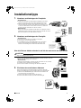
Innengerät-Installationszeichnungen
A
Schrauben
(M4 × 16L)
Montageplatte
Klammer
Markierung
(Rückseite)
Bodenrahmen
Frontgrill
30mm oder mehr von der Decke
Frontplatte
50mm oder mehr von der
Wand (auf beiden Seiten)
Luftfilter
A Montageplatte
Luftfilter
Fotokatalytischer
Titan-Apatit-
Luftreinigungsfilter
Filterrahmen
Nase
Montageplatten-
Befestigungsschraube
(M4 × 25L)
Die Montageplatte sollte an
einer Wand angebracht werden,
die das Gewicht des Innengeräts
tragen kann.
Anbringen des Innengeräts
Haken Sie die Klemmen des
Bodenrahmens auf der Montageplatte ein.
Wenn sich die Klemmen nur schwer
einhaken lassen, nehmen Sie den
Frontgrill ab.
Entfernen des Innengeräts
Drücken Sie den markierten Bereich
(am unteren Teil des Frontgrills) nach
oben, um die Klemmen zu lösen. Wenn
sie sich nur schwer lösen lassen,
nehmen Sie den Frontgrill ab.
Das Wärmeisolationsrohr auf
eine angemessene Länge
zuschneiden und mit Band
umwickeln. Hierbei
sicherstellen, dass am Schnitt
des Wärmeisolationsrohrs kein
Spalt verbleibt.
Das
Rohrloch
mit Kitt
abdichten.
Die Wärmeisolierung von
unten nach oben mit
Schutzband umwickeln.
Fotokatalytischer Titan-Apatit-
Luftreinigungsfilter (2)
C
Öffnen des Wartungsdeckels
Der Wartungsdeckel ist ein
Öffnungs-/Schließungstyp.
Öffnungsmethode
1)
Entfernen Sie die Schrauben
des Wartungsdeckels.
2) Ziehen Sie den Wartungsdeckel in
Pfeilrichtung diagonal nach unten
heraus.
3)
Nach unten ziehen.
Wartungsdeckel
B
F Befestigungsschrauben für
den Fernbedienungshalter
(M3 × 20L)
D
Drahtlose
Fernbedienung
E
Fernbedienungshalter
Stellen Sie vor dem
Anschrauben des
Fernbedienungshalters an
die Wand sicher, dass die
Steuersignale richtig vom
Innengerät empfangen
werden.
02_DE_3P257187-1A.fm Page 4 Thursday, November 12, 2009 12:05 PM

■Deutsch 5
Deutsch
Installation des Innengeräts
1.
Installieren der Montageplatte
• Die Montageplatte sollte an einer Wand angebracht werden, die das Gewicht des Innengeräts tragen kann.
1) Sichern Sie die Montageplatte vorübergehend an der Wand, stellen Sie sicher, dass sie völlig waagerecht ist, und
markieren Sie die Bohrpunkte an der Wand.
2) Befestigen Sie die Montageplatte mit Schrauben an der Wand.
Empfohlene Haltepunkte für die Montageplatte und Abmessungen
770
Verwenden Sie ein
Maßband wie dargestellt.
Bringen Sie das Ende des
Maßbandes in die Position .
Bewahren Sie das aus dem Gerät herausgeschnittene
Stück für die Rohrleitungen hier auf
Einheit: mm
Gasrohrende
Ausgebaute
Rohranschlussabdeckung
A
Montageplatte
Wandöffnung φ65mm
Empfohlene Haltepunkte der
Montageplatte. (insgesamt 5 Punkte)
Setzen Sie einen
Nivellierer auf die
angehobene Nase.
41,3
41,3
241,7
54
330,5
241,7
160
54,5
50160
101120,5
331
203 247
Position des
Ablaufschlauchs
Flüssigkeitsrohrende
*
Die ausgebaute Rohranschlussabdeckung
kann in der Tasche der Montageplatte
aufbewahrt werden.
02_DE_3P257187-1A.fm Page 5 Thursday, November 12, 2009 12:05 PM

6 ■Deutsch
Installation des Innengeräts
2.
Bohren eines Lochs durch die Wand und Anbringen des Wanddurchbruchrohrs
• Verwenden Sie für Wände mit Metallrahmen oder Metallplatten ein
Wanddurchbruchrohr und eine Wandabdeckung im Durchführungsloch,
um mögliche Hitze, elektrischen Schlag oder Brand zu verhüten.
• Achten Sie darauf, die Hohlräume um die Rohre herum mit Dichtmaterial
abzudichten, um Lecken von Wasser zu verhüten.
1) Bohren Sie ein Durchführungsloch mit einem Durchmesser von
65mm nach außen hin abwärts geneigt durch die Wand.
2) Schieben Sie ein Wanddurchbruchrohr in das Loch.
3) Bringen Sie eine Wandabdeckung am Wanddurchbruchrohr an.
4) Dichten Sie die Rohrhohlräume nach Fertigstellung der Kältemittel-
Rohrleitung, Verdrahtung und der Ablassverrohrung mit Kitt ab.
3.
Installieren des Innengeräts
• Falls die Kältemittelleitungen gebogen oder ausgehärtet werden müssen,
beachten Sie die folgenden Vorsichtsmaßnahmen.
Bei unsachgemäßer Arbeit können ungewöhnliche Geräusche erzeugt
werden.
1) Drücken Sie die Kältemittelleitungen nicht zu stark gegen den
Bodenrahmen.
2) Drücken Sie die Kältemittelleitungen auch nicht zu stark gegen den
Frontgrill.
3-1.
Rohrleitung rechte Seite, Rohrleitung rechts
hinten oder Rohrleitung rechts unten
1) Befestigen Sie den Ablaufschlauch mit Vinylklebeband an der
Unterseite der Kältemittelleitung.
2) Umwickeln Sie die Kältemittelleitungen und den Ablaufschlauch
zusammen mit Isolierband.
3) Schieben Sie den Ablaufschlauch und die Kältemittelrohre
durch das Loch in der Wand, und hängen Sie dann das Innengerät
unter Verwendung der Markierungen an der Oberseite des
Innengeräts als Hinweise auf die Haken der Montageplatte.
4) Die Frontplatte öffnen, dann den Wartungsdeckel öffnen.
(Siehe die Installationstipps.)
5) Führen Sie das Geräte-Verbindungskabel vom Außengerät
durch die Wanddurchgangsöffnung an der Rückseite des
Innengeräts. Ziehen Sie es zur Vorderseite. Biegen Sie die
Enden der Bindedrähte nach oben, um später besser damit
arbeiten zu können. (Falls die Enden des Geräte-
Verbindungskabels zunächst abisoliert werden müssen,
bündeln Sie die Drahtenden mit Klebeband.)
6) Drücken Sie den Bodenrahmen des Innengeräts mit beiden
Händen auf die Haken der Montageplatte. Achten Sie darauf,
dass die Drähte nicht an der Kante des Innengeräts
eingeklemmt werden.
Innen Außen
Abdichtung
Wanddurchbruchrohr
(vor Ort zu beschaffen)
Wandblende
(vor Ort zu
beschaffen)
Wanddurchbruchrohr
(vor Ort zu beschaffen)
φ65
1)
2)
Rohrleitung
rechts unten
Rohrleitung rechts
hinten
Entfernen Sie die
Rohranschlussabdeckung
hier für die Rohrleitung auf
der rechten Seite.
Entfernen Sie die Rohranschlussabdeckung
hier für die Rohrleitung rechts unten.
Binden Sie das
Kältemittelrohr und
den Ablaufschlauch
mit Isolierband
zusammen.
Montageplatte
A
Drahtführung
Das Innengerät hier einhaken.
Geräte-
Verbindungskabel
Montageplatte
A
Wenn die Enden der
Geräte-Verbindungskabel
im voraus abisoliert
werden, binden Sie die
Kabelenden mit
Isolierband zusammen.
02_DE_3P257187-1A.fm Page 6 Thursday, November 12, 2009 12:05 PM

■Deutsch 7
Deutsch
3-2.
Rohrleitung linke Seite, Rohrleitung links hinten oder Seite oder Rohrleitung links unten
1) Bringen Sie den Ablaufschlauch mit Vinylklebeband an
der Unterseite der Kältemittelrohre an.
2) Schließen Sie den Ablaufschlauch nicht an eine
Ablassschraube, sondern an den Abflussstutzen an.
3) Formen Sie das Kältemittelrohr entlang der
Rohrpfadmarkierung an der Montageplatte.
4)
Schieben Sie den Ablaufschlauch und die
Kältemittelrohre durch das Loch in der
Wand, und hängen Sie dann das Innengerät
unter Verwendung der Markierungen an
der Oberseite des Innengeräts als Hinweise
auf die Haken der Montageplatte.
5) Ziehen Sie die Geräte-Verbindungskabel
herein.
6) Die Geräte-Verbindungsrohre anschließen.
7) Die Kältemittelleitungen und den
Ablaufschlauch mit Isolierband zusammenbinden, wie in der Abbildung
rechts gezeigt, wenn der Ablaufschlauch durch die Rückseite des
Innengeräts geht.
8) Drücken Sie die Unterkante des Innengeräts mit beiden Händen, bis es
fest in die Haken der Montageplatte einrastet, wobei Sie darauf achten
müssen, dass sich die Geräte-Verbindungskabel nicht am Innengerät
verfangen. Sichern Sie das Innengerät mit Innengerät-
Befestigungsschrauben (M4 × 12L) auf der Montageplatte.
3-3. Wanddurchbruchrohr
Die Anweisungen unter Rohrleitung linke Seite, links hinten oder links
unten befolgen.
1) Schieben Sie den Ablaufschlauch bis zu dieser Tiefe ein, damit er
nicht aus der Ablaufleitung herausgezogen wird.
• Austausch auf der linken Seite
1) Entfernen Sie die Isolierungs-
Befestigungsschraube auf der rechten Seite,
um den Ablaufschlauch abzunehmen.
2)
Drehen Sie die Isolierungs-Befestigungsschraube
auf der rechten Seite wieder ein.
*
(Wird dies vergessen, kann Wasser austreten.)
3)
Entfernen Sie die Ablassschraube auf der linken
Seite, und bringen Sie sie auf der rechten Seite an.
4) Führen Sie den Ablaufschlauch ein, und
befestigen Sie ihn mit der mitgelieferten
Innengerät-Befestigungsschraube.
Austauschen der Ablassschraube und des Ablaufschlauchs
Anbringungsposition des Ablaufschlauchs
*Der Ablaufschlauch befindet sich auf der Rückseite des Geräts.
Vorderseite des Geräts
Anbringung auf der rechten Seite (Werksvorgabe)
Anbringung auf der linken Seite
Ablaufschlauch Ablaufschlauch
Innengerät-
Befestigungsschraube
Isolierungs-
Befestigungsschraube
Rechte SeiteLinke Seite
Rohrleitung links unten
Rohrleitung links
Rohrleitung links hinten
Entfernen Sie die Rohransachlussabdeckung
hier für die Rohrleitung links unten.
Entfernen Sie die
Rohransachlussabdeckung
hier für die Rohrleitung auf
der linken Seite.
Anbringen der Ablassschraube.
Einen Sechskantschlüssel (4mm) einschieben.
Kein
Spalt.
Beim Einführen kein Schmieröl
(Kältemittelöl) auftragen.
Auftragen von Öl verursacht
Verschlechterung und Lecken von
Ablass an der Verschlussschraube.
Ablaufschlauch
Dichten Sie diese
Öffnung mit Kitt oder
Dichtungsmaterial ab.
Mit Kunststoffband
verbinden.
A
Montageplatte
Wickeln Sie Isolierband um den gebogenen
Abschnitt der Kältemittelleitung.
Lassen Sie das Isolierband bei jeder
Wicklung um mindestens die halbe Breite
des Bands überlappen.
Kältemittelleitungen
Ablaufschlauch
Bodenrahmen
H Innengerät-Befestigungsschraube
(M4 × 12L) (2 Punkte)
Montageplatte
A
Geräte-Verbindungskabel
Innenwand
Vinylchlorid-
Ablaufleitung (VP30)
Ablaufschlauch50mm o
der mehr
Außenwand
Schieben Sie den
Ablaufschlauch bis zu dieser
Tiefe ein, damit er nicht aus
der Ablaufleitung
herausgezogen wird.
02_DE_3P257187-1A.fm Page 7 Thursday, November 12, 2009 12:05 PM
La page charge ...
La page charge ...
La page charge ...
La page charge ...
La page charge ...
La page charge ...
La page charge ...
La page charge ...
La page charge ...
La page charge ...
La page charge ...
La page charge ...
La page charge ...
La page charge ...
La page charge ...
La page charge ...
La page charge ...
La page charge ...
La page charge ...
La page charge ...
La page charge ...
La page charge ...
La page charge ...
La page charge ...
La page charge ...
La page charge ...
La page charge ...
La page charge ...
La page charge ...
La page charge ...
La page charge ...
La page charge ...
La page charge ...
La page charge ...
La page charge ...
La page charge ...
La page charge ...
La page charge ...
La page charge ...
La page charge ...
La page charge ...
La page charge ...
La page charge ...
La page charge ...
La page charge ...
La page charge ...
La page charge ...
La page charge ...
La page charge ...
La page charge ...
La page charge ...
La page charge ...
La page charge ...
La page charge ...
-
 1
1
-
 2
2
-
 3
3
-
 4
4
-
 5
5
-
 6
6
-
 7
7
-
 8
8
-
 9
9
-
 10
10
-
 11
11
-
 12
12
-
 13
13
-
 14
14
-
 15
15
-
 16
16
-
 17
17
-
 18
18
-
 19
19
-
 20
20
-
 21
21
-
 22
22
-
 23
23
-
 24
24
-
 25
25
-
 26
26
-
 27
27
-
 28
28
-
 29
29
-
 30
30
-
 31
31
-
 32
32
-
 33
33
-
 34
34
-
 35
35
-
 36
36
-
 37
37
-
 38
38
-
 39
39
-
 40
40
-
 41
41
-
 42
42
-
 43
43
-
 44
44
-
 45
45
-
 46
46
-
 47
47
-
 48
48
-
 49
49
-
 50
50
-
 51
51
-
 52
52
-
 53
53
-
 54
54
-
 55
55
-
 56
56
-
 57
57
-
 58
58
-
 59
59
-
 60
60
-
 61
61
-
 62
62
-
 63
63
-
 64
64
-
 65
65
-
 66
66
-
 67
67
-
 68
68
-
 69
69
-
 70
70
-
 71
71
-
 72
72
-
 73
73
-
 74
74


McQuay M5WMY10KR Guide d'installation
- Catégorie
- Climatiseurs split-system
- Taper
- Guide d'installation
- Ce manuel convient également à
dans d''autres langues
- italiano: McQuay M5WMY10KR Guida d'installazione
- English: McQuay M5WMY10KR Installation guide
- español: McQuay M5WMY10KR Guía de instalación
- Deutsch: McQuay M5WMY10KR Installationsanleitung
- русский: McQuay M5WMY10KR Инструкция по установке
Autres documents
-
GOODMAN CTXG12QVJUS Guide d'installation
-
Fujitsu ASAG07LMCA Guide d'installation
-
Haier 001051 Manuel utilisateur
-
Daikin FTXB12AXVJU Guide d'installation
-
Fujitsu ASU9RLF1 Guide d'installation
-
Panasonic CS-E24RKUAW Guide d'installation
-
-
-
Mitsubishi Electric PEAD-A36AA Guide d'installation
-
Fujitsu AOU48RLXFZ1 Guide d'installation