Apollo 2ACE9-51000300 Manuel utilisateur
- Catégorie
- Détecteur de fumée
- Taper
- Manuel utilisateur
Ce manuel convient également à

APD0671 A160301
© 2016 Apollo Fire
Copyright © 2016 l 1
51000-300
WIRELESS SMOKE ALARM INTERCONNECT BASE
GENERAL INFORMATION
The Wireless Smoke Alarm Interconnect Base part number 51000-300 is a 120V AC
powered sensor. It monitors the interconnect line on interconnected hardwired smoke
alarm systems and sends out a transmission when any of the smoke alarm units on the
same circuit enter an alarm state. The device has LEDs to visually indicate the status of the
interconnect base. A single CR2032 ba ery provides backup power in the event that AC
power is lost on the alarm system circuit. The Wireless Smoke Alarm Interconnect Base
communicates with a compa ble control panel and can send alarm, low ba ery, AC power
loss, and supervisory messages to the system's receiver.
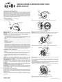
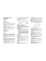
Contents of Carton:
• 1 Wireless Smoke Alarm Interconnect Base
• 2 2" long 10-32 Screws
• 1 CR 2032 3 Volt Coin Ba ery
Figure 1. 51000-300 Kit
IMPORTANT: This device must be tested and maintained regularly. This device is intended
for use with compa ble smoke alarms, but will not detect the presence of smoke, heat, or
re directly.
✓ Note: Each of the smoke alarms part of interconnected smoke alarms must be:
• Present in every required loca on per NFPA 72,11.5.1
• Con rmed as less than ten years from date of installa on (or manufacture). Please
check label on the device or original smoke detector device manual.
• Hardwired to a single, common 120V AC circuit designated for interconnected smoke
alarms.
• Pass the manufacturer's stated tes ng regimen to con rm proper interconnect
opera on.
• Have fresh back-up ba eries.
• On the list of compa ble models (any model not listed may work but has not been
compa bility tested).
• This device shall not be installed in loca ons where the normal ambient temperature
is below 40F(4.4C) or exceeds 100F (37.8C), unless the alarm has been determined
capable of being used at installa on points with higher or lower ambient temperatures.
• Please see sec on at the end regarding informa on on the proper installa on of smoke
alarms that are intended to work with the Wireless Smoke Alarm Interconnect Base.
This device is not intended to work with smoke alarms paired with smoke alarm guards,
unless the combina on has been evaluated and found suitable for this purpose.
Compatible Smoke Alarm Models
• BRK Brands Model 7010B: AC Powered Photoelectric Smoke Alarm with Ba ery
Backup
• Firex Kidde Model i4618: Hardwire Ioniza on Smoke Detector with Ba ery Backup
• First Alert BRK Model 9120B: Hardwired Smoke Alarm with Ba ery Backup
• Kidde Model i12040: 120V AC Wire-in Smoke Alarm with Ba ery Backup
• USI Electric Model 5304: Hardwired Ioniza on Smoke and Fire Alarm with Ba ery
Backup
CAUTION: Before a emp ng installa on, locate the primary electrical circuit that
powers the interconnected hardwired smoke alarm system and shut o or disconnect
power to this circuit. An electrical shock hazard is present if this electrical circuit is not
temporarily disabled during installa on.
AVERTISSEMENT: Avant de commencer l’installa on, trouver le circuit électrique
principal qui alimente le système câblé de détec on de fumée interconnecté
et l’éteindre ou couper l’alimenta on de ce circuit. Un risque d’électrocu on
est présent si ce circuit électrique n’est pas temporairement coupé pendant
l’installa on.
WARNING: Remember to turn on or reconnect power to the primary electrical circuit
that powers the interconnected hardwired smoke alarm system. The re warning system
may be disabled if electrical power is not restored to the system.
ATTENTION : Ne pas oublier d’établir ou de rétablir le courant du circuit électrique
principal qui alimente le système câblé de détec on de fumée interconnecté. Le
système d’alerte incendie serait inopérant si le courant électrique alimentant le
système n’était pas rétabli.
Install Wireless Interconnect Base
Select a smoke alarm that will be used to provide power and communicate to the
wireless interconnect base. Any smoke alarm that is within range of a compa ble
wireless receiver can be selected if the smoke alarm is part of an interconnected
hardwired system.
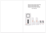
Remove the exis ng smoke alarm from the exis ng moun ng bracket. This is
usually done by twis ng the alarm counter clockwise or clockwise from where it
is mounted.
Figure 2. Remove Exis ng Smoke Alarm from Smoke Alarm Moun ng Base
Figure 3. Unplug Pigtail of Exis ng Smoke Alarm
Unplug the exis ng smoke alarm from the smoke alarm pigtail. Loosen the two screws
used to hold the exis ng moun ng bracket and remove it from the wall or ceiling.
Figure 4. Remove Exis ng Smoke Alarm Moun ng Bracket from Wall or Ceiling
Figure 5. Install Wireless Smoke Alarm Interconnect Base between Wall and
Moun ng Bracket
Place the interconnect base where the exis ng moun ng bracket was located. Make
sure the wire/wiretaps are inserted through the center opening of the smoke alarm
moun ng bracket.
Place the exis ng smoke alarm moun ng bracket on top of interconnect base. Align the
interconnect base and the smoke alarm moun ng bracket and replace the two screws
used to hold the bracket in place. Tighten all screws down.
✓ NOTE: It is suggested that the smoke alarm sensor LEDs be oriented towards the
bo om or in a manner that allows the LEDs on the unit to be visible.
Figure 6. Wiretaps/Wires, & Pigtail through Center
PRINTER’S INSTRUCTIONS:
INSTR,INSTL,APOLLO WIRELESS SMKE ALARM INTERCONNECT BASE - P/N: 10011636 X1- INK: BLACK - MATERIAL: 20 LB. MEAD BOND - SIZE: 8.500” X 11.000” - TOL. +/- .125”- SCALE: 1-1 - FOLDING: FOLD 1X TO FINAL SIZE: 8.500" X 5.500"- FINISH WITH LOGO
SHOWING
+
CR2032
3V
WIRELESS SMOKE ALARM
INTERCONNECT BASE
WIRETAPS
CR2032
COIN BATTERY
10-32 X 2”
SCREWS
SMOKE
EXISTING
SMOKE
ALARM
MOUNTING
BASE
EXISTING
SMOKE
ALARM
ROTAT E
COUNTER
CLOCKWISE
TO REMOVE
EXISTING SMOKE
ALARM
EXISTING SMOKE ALARM
MOUNTING BRACKET
UNPLUG
SMOKE ALARM
FROM EXISTING
POWER PIGTAIL
REMOVE EXISTING SMOKE
ALARM MOUNTING
BRACKET FROM WALL OR
CEILING
EXISTING
SMOKE
ALARM
POWER
PIGTAIL
ACCESS HOLE
IN WALL OR
CEILING
REMOVE
EXISTING
SCREWS
WIRELESS SMOKE
ALARM INTERCONNECT
BASE
EXISTING SMOKE ALARM
MOUNTING BRACKET
EXISTING
POWER
PIGTAIL
WALL ACCESS HOLE
WIRETAPS (3)
(NOT CONNECTED)
WIRELESS SMOKE
ALARM INTERCONNECT
BASE
EXISTING
SMOKE
ALARM
MOUNTING
BRACKET
EXISTING
POWER
PIGTAIL
WIRETAPS (3)
(NOT CONNECTED)
MOUNT BRACKET
WITH LED’S AT BOTTOM
Apollo
WIRELESS SMOKE ALARM INTERCONNECT BASE
MODEL 51000-300

APD0671 A160301
© 2016 Apollo Fire
2 Copyright © 2016
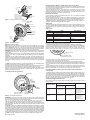
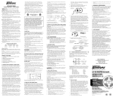
Figure 7. Crimping Wiretaps onto Wires
Figure 8. Wiretap Connec ons
Wiring the Connections
Before connec ng the wires from the interconnect base, iden fy the (+) line (hot)
120VAC wire and the neutral wire. Usually the (+) line (hot) 120VAC wire will be black
and the neutral wire white. Use a voltmeter or voltage sensor to verify that the proper
wires are selected. You may need to reconnect power to the electrical circuit powering
the interconnected hardwired smoke detectors in order to do this (Figure 8).
WARNING: Remember to disconnect or shut o electrical power to the interconnected
hardwired smoke detector if it was powered on in the previous step to iden fy the
120VAC wires.
Use an electrician’s linesman plier or equivalent tool (See Figure 8) and using the installed
wiretaps on the device, crimp the wiretap with the black wire onto the 120VAC line
(hot) wire.
ATTENTION : Ne pas oublier de déconnecter ou couper le courant électrique pour le
détecteur de fumée câblé s’il avait été alimenté auparavant pour iden er les ls 120 AC.
U liser une pince d’électricien ou un ou l équivalent (voir image 8) et en u lisant les
connecteurs installés sur l’appareil, ser r le connecteur avec le l noir sur la ligne 120VAC
(posi f).
✓ NOTE: Wiretaps must be used on a sec on of stranded wire. This is typically located
between the connector to the smoke detector and the wire nut.
The wiretap with the yellow wire should be a ached to the wire lead connected to the
interconnect wire of the smoke detector. This wire is typically yellow or orange.
Once all (3) three wiretaps have been installed (Figure 8), rea ach the electrical wire
pigtail to the back of the smoke detector unit and mount the smoke alarm on the
moun ng base (Refer to Figure 3).
Installing the Back-Up Battery
Figure 9. Installing Back-up Ba ery
WARNING: Ensure that the interconnect base has been wired correctly. Damage to
the interconnect base may occur if the 120 VAC line (hot) wire neutral wire are reversed.
The unit may fail to func on properly if incorrectly wired.
Turn on or reconnect power to the primary electrical circuit that powers the
interconnected hardwired smoke alarm system. The device should now power on.
Use a at bladed tool, slide out the ba ery tray that holds the backup ba ery. Insert
a CR2032A ba ery (included) into the ba ery slot. Slide the ba ery tray back into the
device (Figure 9).
ATTENTION : S’assurer que le détecteur de fumée a été branché correctement. Le capteur
du détecteur de fumée pourrait être endommagé si le l de la ligne 120AC (posi f) et
le l neutre sont inversés. L’appareil pourrait ne pas fonc onner correctement s’il était
mal branché. Etablir ou rétablir le courant du circuit électrique principal qui alimente
le système câblé de détec on de fumée. L’appareil devrait à présent s’allumer. U lisant
un ou l à lame plate, coulisser le roir de la pile de sécurité. Insérer une pile CR2032A
(incluse) dans l’emplacement. Coulisser à nouveau le roir pour le refermer (image 9).
✓ NOTE: Orient the (+) ba ery terminal up so that it is visible when facing the unit.
Programming the Wireless Smoke Alarm Interconnect Base
Follow the instruc ons on how to program a sensor into a compa ble control panel. See
the control panel’s Installa on & Programming Guide for more informa on on how to
learn a sensor into the control panel.
The device should learn in as a sensor device. Use a small paper clip or other sharp
object and carefully insert into the learn/test bu on hole. This will send out an alarm
transmission ID so the the sensor can be learned into a compa ble control panel or can
be used to test that the transmi er is working properly.
Replacing the Battery
If the compa ble control panel shows that this sensor has a low ba ery, the backup
ba ery may need to be replaced.
Use a at headed screw driver or other tool to slide the ba ery tray out of the device.
Remove the ba ery from the tray and replace with a new CR2032A ba ery. Slide the
ba ery tray back into the unit, making sure that the tray is fully inserted into the unit.
✓ NOTE: Use Panasonic CR2032A ba eries or equivalent. Use of another ba ery may
damage or nega vely a ect the opera on of the device.
End-of-Life
The Wireless Smoke Alarm Interconnect Base does not have an End-of-Life (EOL), however
the smoke alarm(s) that this device monitors may have an EOL condi on. Follow the
owner's manual for the smoke alarm regarding instruc ons on proper smoke alarm EOL
condi ons.
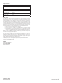
LED Status
Status LEDs Radio Signaling
PowerOn Sequential green, orange, red fl ashes N/A
Normal Green LED fl ash every 48s N/A
Alarm Red fl ash every 1s Alarm
Loss of AC Power
Fault
Orange fl ash every 20s Tamper
Low Battery Fault Orange fl ash every 4s Low Battery
Learn Button Sequential green, orange, red fl ashes Alarm
Testing the Smoke Alarm System
Figure 10. Loca on of LEDs and Learn/Test Bu on Hole
The device should be tested in accordance with NFPA 72 guidelines. The following
instruc ons are intended to provide a general guideline on how to test the smoke alarm
system, wireless smoke alarm interconnect base and communica ons to an alarm panel.
Follow the smoke alarm instruc on manual on tes ng the smoke alarm and any
interconnected units. There usually is a test bu on on the smoke alarm that can be
pressed to ini ate a test mode. This should cause the sounder to alarm and also any
smoke alarms that are interconnected to also alarm.
The interconnect base should send out a transmission to a compa ble alarm panel.
If this transmission is not received, rst check if the Smoke alarm is properly programmed
into a compa ble alarm panel. Please follow the alarm panel instruc ons on learning in
a sensor.
Also, check that the interconnect wire on the smoke alarm is properly connected to the
Wireless Smoke Alarm Interconnect Base. The LEDs on the interconnect base should
ash red indica ng that it has received the alarm signal from the smoke alarm .
Testing the Wireless Smoke Alarm Interconnect Base Radio Trans-
mission Only
The Wireless Interconnect Base incorporates a small test bu on. This test bu on can be
ac vated by inser ng a straightened paper clip or sharp object into the Learn/Test hole.
The Smoke Detector Sensor will then send an alarm signal transmission to a compa ble
alarm panel. This can be used to test that the Wireless Smoke Alarm Interconnect Base
will send a proper transmission to an alarm panel. This DOES NOT test if the wiring
between the smoke alarm and the interconnect base is correct.
Troubleshooting Installation Chart
When tes ng the Wireless Smoke Alarm Interconnect Base sensor, check for these
common issues.
Condition
Smoke Alarm
Result Resolution
Wireless Smoke Alarm
Interconnect Base LED
Alarm Panel
Smoke detector is in
alarm mode
LED on interconnect base
do not work properly
Alarm panel does not
receive alarm signals
Check to make sure
interconnect wire from
the smoke alarm is
properly connected to the
interconnect base
Smoke detector is in
alarm mode
LED on interconnect base
sensor works properly
Alarm panel does not
receive alarm signals
Check to make sure
the interconnect base
is properly learned or
programmed into a
compatible alarm panel
EXISTING
POWER
PIGTAIL
WIRETAPS (3)
CRIMPED
TO PRIMARY
CIRCUIT WIRES
WIRING CODE:
• BLACK TO BLACK (120 VAC)
• WHITE TO WHITE (NEUTRAL)
• YELLOW TO YELLOW OR
ORANGE (INTERCONNECT)
PRIMARY POWER
WIRING
WHT/WHT (NEUTRAL)
BLK/BLK (120VAC)
YEL/YEL OR
YEL/ORANGE
+
CR2032
3V
MOVE TO
FRESH AIR
SMOKE
+
CR2032
3V
STEP 1
PULL OUT
BATTERY TRAY
WITH FLATHEAD
SCREWDRIVER
STEP 2
INSERT
BATTERY + POLARITY
FACING UP
WIRELESS SMOKE ALARM
INTERCONNECT BASE
SMOKE ALARM
LEDS ON WIRELESS SMOKE
ALARM INTERCONNECT BASE
LEARN/TEST BUTTON
HOLE
1. PLACE WIRE
INTO
WIRETAP.
2. HINGE WIRETAP
UP AND OVER
WIRE STRAND
3. CRIMP
WIRETAP WITH
PLIERS
WIRING CODE:
•BLACK TO BLACK (120 VAC)
•WHITE TO WHITE (NEUTRAL)
•YELLOW TO YELLOW OR
ORANGE (INTERCONNECT)

APD0671 A160301
© 2016 Apollo Fire
Copyright © 2016 l 3
Specifi cations
Input Power 120VAC 50/60Hz 12W
Backup Power 3-Volt CR2032 Battery or Equivalent
Backup Battery Life >8 years
Operating Temperature 32°F to 122°F (0°C to 50°C)
Operating Humidity 5–95% RH non-condensing
Compatibility ADT Lynx and ADT Vista
Wireless Signal Range 350ft (110m)
Supervisory Interval 70 minutes
Certifi cation FCC/IC and ETL
FCC Notice
This device complies with Part 15 of the FCC’s Rules. Opera on is subject to the following two condi ons:
1 This device may not cause harmful interference, and 2 This device must accept any interference received,
including interference that may cause undesired opera on. This equipment has been tested and found to
comply with the limits for a Class B digital device, pursuant to Part 15 of the FCC Rules. These limits are
designed to provide reasonable protec on against harmful interference in a residen al installa on.
This equipment generates, uses and can radiate radio frequency energy and, if not installed and used in
accordance with the instruc ons, may cause harmful interference to radio communica ons. However, there is
no guarantee that interference will not occur in a par cular installa on. If this equipment does cause harmful
interference to radio or television recep on, which can be determined by turning the equipment o and on,
the user is encouraged to try to correct the interference by one or more of the following measures:
✓ Reorient or relocate the receiving antenna.
✓ Increase the separation between the equipment and receiver.
✓ Connect the equipment into an outlet on a circuit different from that to which the receiver is
connected.
✓ Consult the dealer or an experienced radio/TV technician for help. To satisfy FCC/IC RF exposure safety
requirements, a separation distance of 20 cm or more should be maintained between this device and
person’s body (excluding extremities: hands, wrists, feet, and ankles).
NOTE: Any changes or modi ca ons not expressly approved by the party responsible for compliance could
void the user’s authority to operate this equipment.
Industry Canada (IC) Compliance
This device complies with Industry Canada license-exempt RSS standard(s). Opera on is subject to the
following two condi ons: (1) this device may not cause interference, and (2) this device must accept any
interference, including interference that may cause undesired opera on of the device.
Le présent appareil est conforme aux CNR d’Industrie Canada applicables aux appareils radio exempts de
licence. L’exploita on est autorisée aux deux condi ons suivantes:
1 l’appareil ne doit pas produire de brouillage, et 2 l’u lisateur de l’appareil doit accepter tout brouillage
radioélectrique subi, même si le brouillage est suscep ble d’en comprome re le fonc onnement.
This Class B digital apparatus complies with Canadian ICES-003. Cet appareil numérique de la classe B est
conforme à la norme NMB-003 du Canada.
Apollo
25 Corporate Drive
Auburn Hills, MI 48326 USA
TEL: +1-248-332-3900
FAX: +1-248-332-8807
www.apollo- re.com
10011636 X1

APD0671 A160301
© 2016 Apollo Fire
25 Corporate Drive
Auburn Hills, Michigan 48326
+1 (248) 332-3900 FAX: +1 (248) 332-8807
www.apollo-re.com • SalesUSA@apollo-re.com
-
 1
1
-
 2
2
-
 3
3
-
 4
4


Apollo 2ACE9-51000300 Manuel utilisateur
- Catégorie
- Détecteur de fumée
- Taper
- Manuel utilisateur
- Ce manuel convient également à
dans d''autres langues
- English: Apollo 2ACE9-51000300 User manual
Documents connexes
Autres documents
-
Perixx PERIMICE-819 Manuel utilisateur
-
Perixx PERIMICE-813 Manuel utilisateur
-
Perixx PERIBOARD-813 Manuel utilisateur
-
 DMP Electronics 1166 Guide d'installation
-
 Qbic Luminen 10 Touch Panel PC Mode d'emploi
-
Kidde SM120X Manuel utilisateur
-
 American Sensor ASD200 Le manuel du propriétaire
-
 Tiiwee X1 XL Manuel utilisateur
-
BRK RM4 Manuel utilisateur
-
 American Sensor ESA5011 Manuel utilisateur


