
1-Page_entete
WARNING
ATTENTION
A11 OFF
NON
*
HOOD
PIN
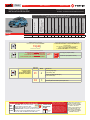
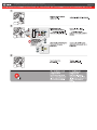
HOOD STATUS : THE HOOD PIN SWITCH (INCLUDED)
MUST BE INSTALLED IF THE VEHICLE CAN BE
REMOTE STARTED WITH THE HOOD OPEN, SET FUNCTION A11 TO OFF.
CONTACT
DE CAPOT
SECURITY STICKER
AUTOCOLLANT DE
SÉCURITÉ
MANDATORY INSTALL | INSTALLATION OBLIGATOIRE Notice: the installation of safety
elements are mandatory. The hood pin
and the sticker are essential security
elements and must be installed.
Notice: l'installation des éléments de
sécurité est obligatoire. Le contact de
capot et l'autocollant de sécurité sont
des éléments de sécurité essentiels et
doivent absolument être installés.
THIS MODULE MUST BE INSTALLED BY A
QUALIFIED TECHNICIAN. A WRONG
CONNECTION CAN CAUSE PERMANENT
DAMAGE TO THE VEHICLE.
CE MODULE DOIT ÊTRE INSTALLÉ PAR
UN TECHNICIEN QUALIFIÉ, TOUTE
ERREUR DANS LES BRANCHEMENTS
PEUT OCCASIONNER DES DOMMAGES
PERMANENTS AU VÉHICULE.
STATUT DE CAPOT : LE CONTACT DE CAPOT (INCLUS), DOIT ÊTRE
INSTALLÉ SI LE VÉHICULE PEUT DÉMARRER À DISTANCE, LORSQUE LE
CAPOT EST OUVERT, PROGRAMMEZ LA FONCTION A11 À NON.
Included
Inclus
ONE REV.: 20211013
ADDENDUM - SUGGESTED WIRING CONFIGURATION
ADDENDA - SCHÉMA DE BRANCHEMENT SUGGÉRÉ
32 3DK.Blue (GWR) Shut Down After
BleuFoncé (Masse d’activation) Sortie après l’arret.
Program remote
starter option:
Programmez l’option
démarreur à distance:
FUNCTION
FONCTION MODE DESCRIPTION
31 4
(+) Parking Light (E1)
(+) Accessory (E2)
(+) Feux de stationnement (E1)
(+) Accessoire (E2)
IF THE VEHICLE IS NOT EQUIPPED
WITH FUNCTIONAL HOOD PIN:
SI LE VÉHICULE N’EST PAS ÉQUIPÉ
D’UN CONTACT DE CAPOT FONCTIONNEL: A11 OFF
NON
Hood trigger (Output Status).
Contact de capot (état de sortie).
BYPASS FIRMWARE VERSION
VERSION LOGICIELLE CONTOURNEMENT
To add the rmware version and the options, use the
FLASH LINK UPDATER or FLASH LINK MOBILE tool,
sold separately.
Pour ajouter la version logicielle et les options,
utilisez l’outil FLASH LINK UPDATER
ou FLASH LINK MOBILE, vendu séparément.
72.[48]
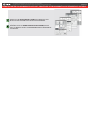
NISSAN/INFINITI MINIMUM
Vehicle functions supported in this diagram (functional if equipped) | Fonctions du véhicule supportées
dans ce diagramme (fonctionnelles si équipé)
VEHICLE
VEHICULES
YEARS
ANNÉES
Immobilizer bypass
T-Harness available (sold
separately)
Harnais en T disponible
(vendu séparément)
Lock
Arm
Unlock
Disarm
Parking Lights
Horn
Tachometer
Door Status
Trunk Status
Hood Status
Hand-Brake Status
Foot-Brake Status
NISSAN
Micra 2015-2018 • • ••••••••••••
Guide # 72051
Page 1 / 7
REGULAR INSTALLATION
INSTALLATION RÉGULIÈRE

This guide may change without notice. See www.fortin.ca for latest version.
Ce guide peut faire l’objet de changement sans préavis. Voir www.fortin.ca pour la récente version.
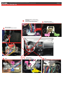
DESCRIPTION | DESCRIPTION
Ignition harness
Connecteur d'ignition
Transponder connector
Connecteur du transpondeur
BCM
(-)LOCK(-)UNLOCK
Driver kick panel
Panneau latérale côté conducteur
(+)PARKING
LIGHTS
OBDII
(+)ACCESSORY
(+)START
(+)IGNITION
(+)12V
TX
RX
At steering column * Test wire before
connecting
au conneteur à la colonne de direction
*testez le fil avant de branchement
(-)HORN
CAN
HIGH
CAN
LOW
Page 2 / 7

Yellow In A1
Purple Out A2
Purple/White Out A3
Green Out A4
White Out A5
Orange Out A6
Orange/Black Out A7
Dk.Blue Out A8
Red/Blue In A9
Lt.Blue/Black In/Out A10
Black In A11
Pink Out A12
Yellow/Black Out A13
Brown/White In A14
Pink/Black In A15
Purple/Yellow In/Out A16
Green/White In/Out A17
Green/Red In/Out A18
White/Black Out A19
Lt.Blue In/Out A20
C5 Brown
C4 Gray/Black
C3 Gray
C2 Orange/Brown
C1 Orange/Green
D6 White/Red
D5 White/Blue
D4 White/Green
D3 Yellow/Red
D2 Yellow/Blue
D1 Yellow/Green
White Out E1
Orange Out E2
Red In E3
Black In E4
Pink In/Out E5
Yellow Out E6
This guide may change without notice. See www.fortin.ca for latest version.
Ce guide peut faire l’objet de changement sans préavis. Voir www.fortin.ca pour la récente version.
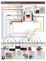
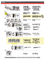
WIRING CONNECTION | GUIDE DE BRANCHEMENTS
(-) Hood pin
HOOD PIN
CONTACT CAPOT
CUT LOOP FOR AUTOMATIC
TRANSMISSION MODE.
COUPEZ LA BOUCLE POUR LE
MODE TRANSMISSION
AUTOMATIQUE.
CAN HIGH
CAN LOW
(+)Starter
(+)Ignion
(-)Ground
(+)12V
(+)Accessory
(+)Parking lights
(-)Horn
(-)Disarm
(-)Unlock
(-)Lock
(+)Ignion
A2
A3
A4
A5
A6
A7
A8
A9
A10
A11
A12
A13
A14
A15
A16
A17
A18
A19
A20
E1
E2
E3
E4
E5
E6
C5
C4
C3
C2
C1
D6
D5
D4
D3
D2
D1
A1
D2
D4
D5
D6
C1
C2
C5
A19
A18
A17
A14
A13
A12
A11
A9
A5
A4
A7
A3/A6
A3/A6
A2 A8 E1 C3 C4
(-)Driver door Pin
E3 E6 E5/A1 E2
Ground
Masse
D3
D1A10/A16
(~)TX
(~)RX
(~)TX
(~)TX
(~)TX
A20
MICRA
WITH OEN ALARM
AVEC ALARME
D'ORIGINE
BCM White
connector -
Back view
BCM -
Connecteur
Blanc - Vue de
dos
(-)LOCK (-)UNLOCK
Gray
Gris White
Blanc
67810 11 16 17 18
14 15
25 26 28 29 30 31 32 33 35 36 37 38 39 40
19 20
27
13
12
9
34
1 2 3 4 5
21 22 23 24
Driver kick panel -
Grey connector -
Back view
Panneau latérale
côté conducteur -
Connecteur gris -
Vue de dos
(+)PARKING
LIGHTS
Red
Rouge
10
4567
8 9 1614 15131211
1 2 3
14
61234567 8
9 10 11 12 13 14 15 16
OBDII
Front view
Vue de face
CAN
HIGH CAN
LOW
Pink
Rose
Blue
Bleu
Back vue. 15-pin
Black connector at
BCM.
Vue de dos.
Connecteur Noir de
15-pins au BCM.
(-)DRIVER
DOOR PIN
Lt.Blue
Bleu Pâle
or Blue
ou Bleu
For Autolight shut
down.
Pour la fermeture des
lumières automatique.
64
70
6362616059585756
6665 67 68 69
1
4
23
6
5
(+)ACCESSORY(+)START
(+)IGNITION
(+)12V
Yellow
Jaune
Gray
Gris
White
Blanc
Pink
Rose
Ignition harness
White connector -
Back view
Connecteur
d'ignition
Connecteur Blanc -
Vue de dos
21 3 4
LOCK
ON
START
Ignition
Barrel
Barillet
d'ignition
Transponder connector
White connector - Back
view
Connecteur du
transpondeur
Connecteur Blanc - Vue
de dos
(~)TX(~)RX
Lt.Green
Vert Pâle
Pink
Rose
CUT
6578
34 2 1
(-)HORN
Red
Rouge Steering column
Grey connector -
Back view
Colonne de
direction
Connecteur Gris - Vue
de dos
Page 3 / 7

This guide may change without notice. See www.fortin.ca for latest version.
Ce guide peut faire l’objet de changement sans préavis. Voir www.fortin.ca pour la récente version.
KEY BYPASS PROGRAMMING PROCEDURE 1/2 | PROCÉDURE DE PROGRAMMATION CONTOURNEMENT DE CLÉ 1/2
Page 4 / 7

This guide may change without notice. See www.fortin.ca for latest version.
Ce guide peut faire l’objet de changement sans préavis. Voir www.fortin.ca pour la récente version.
KEY BYPASS PROGRAMMING PROCEDURE 2/2 | PROCÉDURE DE PROGRAMMATION CONTOURNEMENT DE CLÉ 2/2
Page 5 / 7

This guide may change without notice. See www.fortin.ca for latest version.
Ce guide peut faire l’objet de changement sans préavis. Voir www.fortin.ca pour la récente version.
REMOTE STARTER PROGRAMMING PROCEDURE | PROCÉDURE DE PROGRAMMATION DU DÉMARREUR À DISTANCE
REFER TO THE QUICK INSTALL GUIDE INCLUDED WITH THE
MODULE FOR THE REMOTE STARTER PROGRAMMING.
RÉFÉREZ-VOUS AU GUIDE D’INSTALLATION RAPIDE INCLUS
AVEC LE MODULE POUR LA PROGRAMMATION DU DÉMARREUR
À DISTANCE.
Page 6 / 7

Service No : 000 102 04 2536
Date: xx-xx
INTERFACE MODULE
Made in Canada
PATENTS PENDING US: 2007-228827-A1
www.fortinbypass.com
HARDWARE VERSION
FIRMWARE VERSION
Module label | Étiquette sur le module
Notice: Updated Firmware and Installation Guides
Updated fi rmware and installation guides are posted on our web site on a regular
basis. We recommend that you update this module to the latest fi rmware and
download the latest installation guide(s) prior to the installation of this product.
Notice: Mise à jour microprogramme et Guides d’installations
Des mises à jour du Firmware (microprogramme) et des guides d’installation
sont mis en ligne régulièrement. Vérifi ez que vous avez bien la dernière version
logiciel et le dernier guide d’installation avant l’installation de ce produit.
WARNING
The information on this sheet is provided on an (as is) basis with no representation or warranty of accuracy whatsoever.
It is the sole responsibility of the installer to check and verify any circuit before connecting to it. Only a computer safe
logic probe or digital multimeter should be used. FORTIN ELECTRONIC SYSTEMS assumes absolutely no liability or
responsibility whatsoever pertaining to the accuracy or currency of the information supplied. The installation in every case
is the sole responsibility of the installer performing the work and FORTIN ELECTRONIC SYSTEMS assumes no liability
or responsibility whatsoever resulting from any type of installation, whether performed properly, improperly or any other
way. Neither the manufacturer or distributor of this module is responsible of damages of any kind indirectly or directly
caused by this module, except for the replacement of this module in case of manufacturing defects. This module must be
installed by qualifi ed technician. The information supplied is a guide only. This instruction guide may change without
notice. Visit www.fortinbypass.com to get the latest version.
MISE EN GARDE
L’information de ce guide est fournie sur la base de représentation (telle quelle) sans aucune garantie de précision et
d’exactitude. Il est de la seule responsabilité de l’installateur de vérifi er tous les fi ls et circuits avant d’effectuer les connexions.
Seuls une sonde logique ou un multimètre digital doivent être utilisés. FORTIN SYSTÈMES ÉLECTRONIQUES n’assume
aucune responsabilité de l’exactitude de l’information fournie. L’installation (dans chaque cas) est la responsabilité de
l’installateur effectuant le travail. FORTIN SYSTÈMES ÉLECTRONIQUES n’assume aucune responsabilité suite à
l’installation, que celle-ci soit bonne, mauvaise ou de n’importe autre type. Ni le manufacturier, ni le distributeur ne se
considèrent responsables des dommages causés ou ayant pu être causés, indirectement ou directement, par ce module,
excepté le remplacement de ce module en cas de défectuosité de fabrication. Ce module doit être installé par un technicien
qualifi é. L’information fournie dans ce guide est une suggestion. Ce guide d’instruction peut faire l’objet de changement
sans préavis. Consultez le www.fortinbypass.com pour voir la plus récente version.
Copyright © 2006-2018, FORTIN AUTO RADIO INC ALL RIGHTS RESERVED PATENT PENDING
TECH SUPPORT
Tél: 514-255-HELP (4357)
1-877-336-7797
ADDENDUM GUIDE WEB UPDATE | MISE À JOUR INTERNET
www.fortinbypass.com
ONE
Page 7 / 7
-
 1
1
-
 2
2
-
 3
3
-
 4
4
-
 5
5
-
 6
6
-
 7
7


dans d''autres langues
- English: Fortin 72051 Installation guide
Documents connexes
-
Fortin Nissan Micra Guide d'installation
-
-
Fortin 92011 Guide d'installation
-
Fortin 94911 Guide d'installation
-
Fortin 94791 Guide d'installation
-
Fortin 95101 Guide d'installation
-
-
-
Fortin 81851 Guide d'installation