Makita GA7070 Manuel utilisateur
- Catégorie
- Outils électroportatifs
- Taper
- Manuel utilisateur
Ce manuel convient également à

INSTRUCTION MANUAL
MANUEL D'INSTRUCTION
MANUAL DE INSTRUCCIONES
Angle Grinder
Meuleuse d’Angle
Esmeriladora Angular
GA7070
GA9070
IMPORTANT: Read Before Using.
IMPORTANT : Lire avant usage.
IMPORTANTE: Lea antes de usar.
DOUBLE INSULATION
DOUBLE ISOLATION
DOBLE AISLAMIENTO

2ENGLISH
ENGLISH (Original instructions)
SPECIFICATIONS
Model: GA7070 GA9070
Wheel diameter 180mm (7″) 230mm (9″)
Max. wheel thickness 7.2mm (9/32″) 6.5mm (1/4″)
Spindle thread 5/8″
Rated speed (n) 8,500/min 6,600/min
Overall length 506mm (20″)
Net weight 6.1 - 6.6 kg (13.4 - 14.6 lbs) 6.3 - 8.5 kg (13.9 - 18.7 lbs)
•
Due to our continuing program of research and development, the specications herein are subject to change without notice.
• Specications may dier from country to country.
• The weight may dier depending on the attachment(s). The lightest and heaviest combination, according to
EPTA-Procedure 01/2014, are shown in the table.
For Canada only
* If you install optional wheel guard indicated as 7″ on the tool, 180 mm (7″) wheels can be used.
SAFETY WARNINGS
General power tool safety warnings
WARNING: Read all safety warnings, instruc-
tions, illustrations and specications provided
with this power tool. Failure to follow all instructions
listed below may result in electric shock, re and/or
serious injury.
Save all warnings and instruc-
tions for future reference.
The term "power tool" in the warnings refers to your
mains-operated (corded) power tool or BATTERY-
operated (cordless) power tool.
Work area safety
1. Keep work area clean and well lit. Cluttered or
dark areas invite accidents.
2. Do not operate power tools in explosive atmo-
spheres, such as in the presence of ammable
liquids, gases or dust. Power tools create sparks
which may ignite the dust or fumes.
3. Keep children and bystanders away while
operating a power tool. Distractions can cause
you to lose control.
Electrical Safety
1.
Power tool plugs must match the outlet. Never modify
the plug in any way. Do not use any adapter plugs with
earthed (grounded) power tools. Unmodied plugs and
matching outlets will reduce risk of electric shock.
2. Avoid body contact with earthed or grounded
surfaces, such as pipes, radiators, ranges and
refrigerators. There is an increased risk of elec-
tric shock if your body is earthed or grounded.
3. Do not expose power tools to rain or wet con-
ditions. Water entering a power tool will increase
the risk of electric shock.
4. Do not abuse the cord. Never use the cord for
carrying, pulling or unplugging the power tool.
Keep cord away from heat, oil, sharp edges
or moving parts. Damaged or entangled cords
increase the risk of electric shock.
5. When operating a power tool outdoors, use an
extension cord suitable for outdoor use. Use of
a cord suitable for outdoor use reduces the risk of
electric shock.
6. If operating a power tool in a damp location is
unavoidable, use a Residual Current Device
(RCD) protected supply. Use of an RCD reduces
the risk of electric shock.
7.
Power tools can produce electromagnetic elds
(EMF) that are not harmful to the user. However,
users of pacemakers and other similar medical
devices should contact the maker of their device and/
or doctor for advice before operating this power tool.
8. Do not touch the power plug with wet hands.
9. If the cord is damaged, have it replaced by the
manufacturer or his agent in order to avoid a
safety hazard.
Personal Safety
1. Stay alert, watch what you are doing and use
common sense when operating a power tool.
Do not use a power tool while you are tired or
under the inuence of drugs, alcohol or med-
ication. A moment of inattention while operating
power tools may result in serious personal injury.
2. Use personal protective equipment. Always
wear eye protection. Protective equipment such
as dust mask, non-skid safety shoes, hard hat, or
hearing protection used for appropriate conditions
will reduce personal injuries.
3. Prevent unintentional starting. Ensure the
switch is in the o-position before connecting
to power source and/or BATTERY pack, pick-
ing up or carrying the tool. Carrying power tools
with your nger on the switch or energising power
tools that have the switch on invites accidents.

3ENGLISH
4.
Remove any adjusting key or wrench before turning
the power tool on. A wrench or a key left attached to a
rotating part of the power tool may result in personal injury.
5. Do not overreach. Keep proper footing and
balance at all times. This enables better control
of the power tool in unexpected situations.
6. Dress properly. Do not wear loose clothing or
jewellery. Keep your hair, clothing and gloves
away from moving parts. Loose clothes, jewel-
lery or long hair can be caught in moving parts.
7. If devices are provided for the connection of
dust extraction and collection facilities, ensure
these are connected and properly used. Use of
dust collection can reduce dust-related hazards.
8.
Do not let familiarity gained from frequent use
of tools allow you to become complacent and
ignore tool safety principles. A careless action can
cause severe injury within a fraction of a second.
9.
Always wear protective goggles to protect your
eyes from injury when using power tools. The
goggles must comply with ANSI Z87.1 in the USA.
It is an employer's responsibility to enforce the
use of appropriate safety protective equipment
by the tool operators and by other persons in
the immediate working area.
Power tool use and care
1. Do not force the power tool. Use the correct
power tool for your application. The correct
power tool will do the job better and safer at the
rate for which it was designed.
2.
Do not use the power tool if the switch does not turn
it on and o. Any power tool that cannot be controlled
with the switch is dangerous and must be repaired.
3.
Disconnect the plug from the power source and/
or remove the BATTERY pack, if detachable,
from the power tool before making any adjust-
ments, changing accessories, or storing power
tools. Such preventive safety measures reduce the
risk of starting the power tool accidentally.
4.
Store idle power tools out of the reach of children and
do not allow persons unfamiliar with the power tool
or these instructions to operate the power tool. Power
tools are dangerous in the hands of untrained users.
5. Maintain power tools and accessories. Check
for misalignment or binding of moving parts,
breakage of parts and any other condition that
may aect the power tool’s operation. If dam-
aged, have the power tool repaired before use.
Many accidents are caused by poorly maintained
power tools.
6. Keep cutting tools sharp and clean. Properly
maintained cutting tools with sharp cutting edges
are less likely to bind and are easier to control.
7. Use the power tool, accessories and tool bits
etc. in accordance with these instructions, tak-
ing into account the working conditions and
the work to be performed. Use of the power tool
for operations dierent from those intended could
result in a hazardous situation.
8. Keep handles and grasping surfaces dry,
clean and free from oil and grease. Slippery
handles and grasping surfaces do not allow for
safe handling and control of the tool in unexpected
situations.
9. When using the tool, do not wear cloth work
gloves which may be entangled. The entangle-
ment of cloth work gloves in the moving parts may
result in personal injury.
Service
1. Have your power tool serviced by a qualied
repair person using only identical replacement
parts. This will ensure that the safety of the power
tool is maintained.
2. Follow instruction for lubricating and chang-
ing accessories.
To reduce the risk of electric shock, this equipment has
a polarized plug (one blade is wider than the other).
This plug will t in a polarized outlet only one way. If the
plug does not t fully in the outlet, reverse the plug. If it
still does not t, contact a qualied electrician to install
the proper outlet. Do not change the plug in any way.
VOLTAGE WARNING: Before connecting the tool to a
power source (receptacle, outlet, etc.) be sure the volt-
age supplied is the same as that specied on the name-
plate of the tool. A power source with voltage greater
than that specied for the tool can result in SERIOUS
INJURY to the user- as well as damage to the tool. If in
doubt, DO NOT PLUG IN THE TOOL. Using a power
source with voltage less than the nameplate rating is
harmful to the motor.
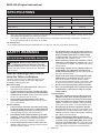
USE PROPER EXTENSION CORD. Make sure your
extension cord is in good condition. When using an
extension cord, be sure to use one heavy enough to
carry the current your product will draw. An undersized
cord will cause a drop in line voltage resulting in loss of
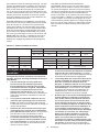
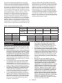
power and overheating. Table 1 shows the correct size
to use depending on cord length and nameplate ampere
rating. If in doubt, use the next heavier gage. The
smaller the gage number, the heavier the cord.
Table 1: Minimum gage for cord
Ampere Rating Volts Total length of cord in feet
120V 25 ft. 50 ft. 100 ft. 150 ft.
220V - 240V 50 ft. 100 ft. 200 ft. 300 ft.
More Than Not More Than AWG
0 A 6 A –18 16 16 14
6 A 10 A 18 16 14 12
10 A 12 A 16 16 14 12
12 A 16 A 14 12 Not Recommended

4ENGLISH
Grinder safety warnings
Safety Warnings Common for Grinding, Sanding,
Wire Brushing, or Abrasive Cutting-O Operations:
1. This power tool is intended to function as a
grinder, sander, wire brush or cut-o tool.
Read all safety warnings, instructions, illus-
trations and specications provided with this
power tool. Failure to follow all instructions listed
below may result in electric shock, re and/or
serious injury.
2.
Operations such as polishing are not recom-
mended to be performed with this power tool.
Operations for which the power tool was not designed
may create a hazard and cause personal injury.
3. Do not use accessories which are not speci-
cally designed and recommended by the tool
manufacturer. Just because the accessory can
be attached to your power tool, it does not assure
safe operation.
4. The rated speed of the accessory must be at
least equal to the maximum speed marked on
the power tool. Accessories running faster than
their rated speed can break and y apart.
5. The outside diameter and the thickness of your
accessory must be within the capacity rating
of your power tool. Incorrectly sized accessories
cannot be adequately guarded or controlled.
6.
Threaded mounting of accessories must match
the grinder spindle thread. For accessories
mounted by anges, the arbour hole of the
accessory must t the locating diameter of the
ange. Accessories that do not match the mounting
hardware of the power tool will run out of balance,
vibrate excessively and may cause loss of control.
7.
Do not use a damaged accessory. Before each
use inspect the accessory such as abrasive
wheels for chips and cracks, backing pad for
cracks, tear or excess wear, wire brush for loose
or cracked wires. If power tool or accessory
is dropped, inspect for damage or install an
undamaged accessory. After inspecting and
installing an accessory, position yourself and
bystanders away from the plane of the rotating
accessory and run the power tool at maximum
no-load speed for one minute. Damaged acces-
sories will normally break apart during this test time.
8. Wear personal protective equipment.
Depending on application, use face shield,
safety goggles or safety glasses. As appro-
priate, wear dust mask, hearing protectors,
gloves and workshop apron capable of stop-
ping small abrasive or workpiece fragments.
The eye protection must be capable of stopping
ying debris generated by various operations.
The dust mask or respirator must be capable of
ltrating particles generated by your operation.
Prolonged exposure to high intensity noise may
cause hearing loss.
9. Keep bystanders a safe distance away from
work area. Anyone entering the work area
must wear personal protective equipment.
Fragments of workpiece or of a broken accessory
may y away and cause injury beyond immediate
area of operation.
10.
Hold the power tool by insulated gripping sur-
faces only, when performing an operation where
the cutting accessory may contact hidden wiring
or its own cord. Cutting accessory contacting a "live"
wire may make exposed metal parts of the power tool
“live” and could give the operator an electric shock.
11. Position the cord clear of the spinning acces-
sory. If you lose control, the cord may be cut or
snagged and your hand or arm may be pulled into
the spinning accessory.
12. Never lay the power tool down until the acces-
sory has come to a complete stop. The spinning
accessory may grab the surface and pull the
power tool out of your control.
13. Do not run the power tool while carrying it at
your side. Accidental contact with the spinning
accessory could snag your clothing, pulling the
accessory into your body.
14. Regularly clean the power tool’s air vents. The
motor’s fan will draw the dust inside the housing
and excessive accumulation of powdered metal
may cause electrical hazards.
15. Do not operate the power tool near ammable
materials. Sparks could ignite these materials.
16. Do not use accessories that require liquid
coolants. Using water or other liquid coolants
may result in electrocution or shock.
Kickback and Related Warnings
Kickback is a sudden reaction to a pinched or snagged
rotating wheel, backing pad, brush or any other acces-
sory. Pinching or snagging causes rapid stalling of the
rotating accessory which in turn causes the uncon-
trolled power tool to be forced in the direction opposite
of the accessory’s rotation at the point of the binding.
For example, if an abrasive wheel is snagged or pinched
by the workpiece, the edge of the wheel that is entering into
the pinch point can dig into the surface of the material caus-
ing the wheel to climb out or kick out. The wheel may either
jump toward or away from the operator, depending on
direction of the wheel’s movement at the point of pinching.
Abrasive wheels may also break under these conditions.
Kickback is the result of power tool misuse and/or
incorrect operating procedures or conditions and can be
avoided by taking proper precautions as given below.
1. Maintain a rm grip on the power tool and
position your body and arm to allow you to
resist kickback forces. Always use auxiliary
handle, if provided, for maximum control over
kickback or torque reaction during start-up.
The operator can control torque reactions or kick-
back forces, if proper precautions are taken.
2. Never place your hand near the rotating acces-
sory. Accessory may kickback over your hand.
3. Do not position your body in the area where
power tool will move if kickback occurs.
Kickback will propel the tool in direction opposite
to the wheel’s movement at the point of snagging.
4. Use special care when working corners, sharp
edges etc. Avoid bouncing and snagging the
accessory. Corners, sharp edges or bouncing
have a tendency to snag the rotating accessory
and cause loss of control or kickback.
5. Do not attach a saw chain woodcarving blade
or toothed saw blade. Such blades create fre-
quent kickback and loss of control.

5ENGLISH
Safety Warnings Specic for Grinding and Abrasive
Cutting-O Operations:
1. Use only wheel types that are recommended
for your power tool and the specic guard
designed for the selected wheel. Wheels for
which the power tool was not designed cannot be
adequately guarded and are unsafe.
2. The grinding surface of centre depressed
wheels must be mounted below the plane of
the guard lip. An improperly mounted wheel that
projects through the plane of the guard lip cannot
be adequately protected.
3. The guard must be securely attached to the
power tool and positioned for maximum safety,
so the least amount of wheel is exposed
towards the operator. The guard helps to protect
the operator from broken wheel fragments, acci-
dental contact with wheel and sparks that could
ignite clothing.
4.
Wheels must be used only for recommended
applications. For example: do not grind with the
side of cut-o wheel. Abrasive cut-o wheels are
intended for peripheral grinding, side forces applied
to these wheels may cause them to shatter.
5. Always use undamaged wheel anges that are
of correct size and shape for your selected
wheel. Proper wheel anges support the wheel
thus reducing the possibility of wheel breakage.
Flanges for cut-o wheels may be dierent from
grinding wheel anges.
6. Do not use worn down wheels from larger
power tools. Wheel intended for larger power tool
is not suitable for the higher speed of a smaller
tool and may burst.
Additional Safety Warnings Specic for Abrasive
Cutting-O Operations:
1. Do not “jam“ the cut-o wheel or apply exces-
sive pressure. Do not attempt to make an
excessive depth of cut. Overstressing the wheel
increases the loading and susceptibility to twisting
or binding of the wheel in the cut and the possibil-
ity of kickback or wheel breakage.
2. Do not position your body in line with and
behind the rotating wheel. When the wheel, at
the point of operation, is moving away from your
body, the possible kickback may propel the spin-
ning wheel and the power tool directly at you.
3. When wheel is binding or when interrupting
a cut for any reason, switch o the power
tool and hold the power tool motionless until
the wheel comes to a complete stop. Never
attempt to remove the cut-o wheel from the
cut while the wheel is in motion otherwise
kickback may occur. Investigate and take correc-
tive action to eliminate the cause of wheel binding.
4.
Do not restart the cutting operation in the work-
piece. Let the wheel reach full speed and carefully
re-enter the cut. The wheel may bind, walk up or
kickback if the power tool is restarted in the workpiece.
5. Support panels or any oversized workpiece to
minimize the risk of wheel pinching and kick-
back. Large workpieces tend to sag under their
own weight. Supports must be placed under the
workpiece near the line of cut and near the edge
of the workpiece on both sides of the wheel.
6. Use extra caution when making a “pocket cut”
into existing walls or other blind areas. The
protruding wheel may cut gas or water pipes, elec-
trical wiring or objects that can cause kickback.
Safety Warnings Specic for Sanding Operations:
1. Do not use excessively oversized sanding
disc paper. Follow manufacturers recommen-
dations, when selecting sanding paper. Larger
sanding paper extending beyond the sanding
pad presents a laceration hazard and may cause
snagging, tearing of the disc or kickback.
Safety Warnings Specic for Wire Brushing
Operations:
1. Be aware that wire bristles are thrown by the
brush even during ordinary operation. Do not
overstress the wires by applying excessive
load to the brush. The wire bristles can easily
penetrate light clothing and/or skin.
2. If the use of a guard is recommended for wire
brushing, do not allow any interference of the
wire wheel or brush with the guard. Wire wheel
or brush may expand in diameter due to work load
and centrifugal forces.
Additional Safety Warnings:
1.
When using depressed centre grinding wheels,
be sure to use only berglass-reinforced wheels.
2. NEVER USE Stone Cup type wheels with this
grinder. This grinder is not designed for these
types of wheels and the use of such a product
may result in serious personal injury.
3. Be careful not to damage the spindle, the
ange (especially the installing surface) or the
lock nut. Damage to these parts could result in
wheel breakage.
4. Make sure the wheel is not contacting the
workpiece before the switch is turned on.
5. Before using the tool on an actual workpiece,
let it run for a while. Watch for vibration or
wobbling that could indicate poor installation
or a poorly balanced wheel.
6. Use the specied surface of the wheel to per-
form the grinding.
7. Do not leave the tool running. Operate the tool
only when hand-held.
8. Do not touch the workpiece immediately after
operation; it may be extremely hot and could
burn your skin.
9. Do not touch accessories immediately after
operation; it may be extremely hot and could
burn your skin.
10. Observe the instructions of the manufacturer
for correct mounting and use of wheels.
Handle and store wheels with care.
11. Do not use separate reducing bushings or
adaptors to adapt large hole abrasive wheels.
12. Use only anges specied for this tool.
13. For tools intended to be tted with threaded
hole wheel, ensure that the thread in the wheel
is long enough to accept the spindle length.
14. Check that the workpiece is properly
supported.
15. Pay attention that the wheel continues to
rotate after the tool is switched o.

6ENGLISH
16. If working place is extremely hot and humid,
or badly polluted by conductive dust, use a
short-circuit breaker (30 mA) to assure opera-
tor safety.
17. Do not use the tool on any materials contain-
ing asbestos.
18. When use cut-o wheel, always work with
the dust collecting wheel guard required by
domestic regulation.
19. Cutting discs must not be subjected to any
lateral pressure.
20. Do not use cloth work gloves during operation.
Fibers from cloth gloves may enter the tool, which
causes tool breakage.
21. Make sure there are no electrical cables, water
pipes, gas pipes etc. that could cause a hazard
if damaged by use of the tool.
SAVE THESE INSTRUCTIONS.
WARNING: DO NOT let comfort or familiarity
with product (gained from repeated use) replace
strict adherence to safety rules for the subject
product. MISUSE or failure to follow the safety
rules stated in this instruction manual may cause
serious personal injury.
Symbols
The followings show the symbols used for tool.
volts
amperes
hertz
alternating current
rated speed
Class II Construction
revolutions or reciprocation per minute
diameter
FUNCTIONAL
DESCRIPTION
CAUTION: Always be sure that the tool is
switched o and unplugged before adjusting or
checking function on the tool.
CAUTION: Return the switch trigger to the
"OFF" position in case of accidental unplugging,
blackout, or the power is cut unintentionally.
Otherwise the tool may start suddenly when the
power returns and it may result in personal injury.
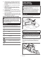
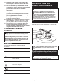
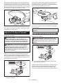
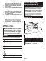
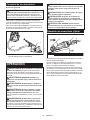
Shaft lock
Press the shaft lock to prevent spindle rotation when
installing or removing accessories.
1
► 1. Shaft lock
NOTICE: Never actuate the shaft lock when the
spindle is moving. The tool may be damaged.
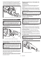
Switch handle mounting positions
CAUTION: Always make sure that the switch
handle is locked in the desired position before
operation.
The switch handle can be rotated to either 90° left or
right to t your work needs. First, unplug the tool. Press
the lock button and rotate the switch handle to left
or right fully. The switch handle will be locked in that
position.
1
2
3
► 1. Motor housing 2. Lock button 3. Handle

7ENGLISH
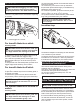
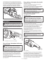
Switch action
CAUTION: Before plugging in the tool, always
check to see that the switch trigger actuates
properly and returns to the "OFF" position when
released.
There are three patterns of the switch action depending
on country.
B
C
2
1
A
► 1. Switch trigger 2. Lock lever
For tool with the lock-on switch
Country specic
CAUTION: Switch can be locked in "ON" posi-
tion for ease of operator comfort during extended
use. Apply caution when locking tool in "ON"
position and maintain rm grasp on tool.
To start the tool, simply pull the switch trigger (in the B
direction). Release the switch trigger to stop.
For continuous operation, pull the switch trigger (in the
B direction) and then push in the lock lever (in the A
direction).
To stop the tool from the locked position, pull the switch
trigger fully (in the B direction), then release it.
For tool with the lock-o switch
Country specic
To prevent the switch trigger from accidentally pulled, a
lock lever is provided.
To start the tool, push in the lock lever (in the A direc-
tion) and then pull the switch trigger (in the B direction).
Release the switch trigger to stop.
NOTICE: Do not pull the switch trigger hard
without pressing in the lock lever. This can cause
switch breakage.
For tool with the lock-on and lock-o
switch
Country specic
CAUTION: Switch can be locked in "ON" posi-
tion for ease of operator comfort during extended
use. Apply caution when locking tool in "ON"
position and maintain rm grasp on tool.
To prevent the switch trigger from accidentally pulled, a
lock lever is provided.
To start the tool, push in the lock lever (in the A direc-
tion) and then pull the switch trigger (in the B direction).
Release the switch trigger to stop.
For continuous operation, push in the lock lever (in the
A direction), pull the switch trigger (in the B direction)
and then pull the lock lever (in the C direction).
To stop the tool from the locked position, pull the switch
trigger fully (in the B direction), then release it.
NOTICE: Do not pull the switch trigger hard
without pressing in the lock lever. This can cause
switch breakage.
Indication lamp
1
► 1. Indication lamp
The indication lamp lights up green when the tool is plugged.
If the indication lamp does not light up, the mains cord
or the controller may be defective.
The indication lamp lights up but the tool does not start even if the
tool is switched on, the controller or the switch may be defective.
If the indicator lamp blinks in red, the carbon brushes
may be worn out or the motor may be defective.
Unintentional restart proof
The tool does not start with the switch being lock-on
even when the tool is plugged.
At this time, the indication lamp blinks in red to show the
unintentional restart proof device is working.
To cancel the unintentional restart proof, return the
switch to OFF position.
NOTE: Wait more than one second before restarting
the tool when unintentional restart proof works.
Active Feedback sensing Technology
CAUTION: Hold the tool rmly until the rota-
tion stops.
The tool electronically detects situations where the wheel
or accessory may be at risk to be bound. In such situation,
the tool automatically shuts o the power to prevent further
rotation of the spindle (this does not prevent kickback).
At this time, the indication lamp blinks in red and shows
the Active Feedback sensing Technology is working.
To restart the tool, switch o the tool rst, remove the
cause of sudden drop in the rotation speed, and then
turn the tool on.

8ENGLISH
Soft start feature
Soft start feature reduces starting reaction.
ASSEMBLY
CAUTION: Always be sure that the tool is
switched o and unplugged before carrying out
any work on the tool.
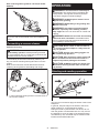
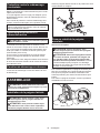
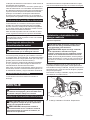
Installing side grip (handle)
CAUTION: Always be sure that the side grip is
installed securely before operation.
CAUTION: You can install the side grip on the
3 holes. Install the side grip on one of the holes
according to the operation.
Screw the side grip securely on the position of the tool
as shown in the gure.
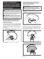
Installing or removing loop handle
Optional accessory
CAUTION: Always be sure the bolts on the
loop handle is securely tightened before use.
CAUTION: Hold the gripping area of the loop
handle specied in the gure. Also, keep the hand
away from the metal part of the grinder during
operation. Touching the metal part may result in
electric shock, if the cutting attachment cuts live wire
unexpectedly.
The loop handle can be more comfortable than the orig-
inal side grip for some applications. To install the loop
handle, mount it onto the tool as illustrated and tighten
two bolts to x it.
To remove the loop handle, follow the installation proce-
dure in reverse.
1
23
► 1. Loop handle 2. Bolt 3. Gripping area
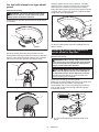
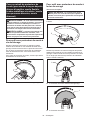
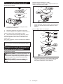
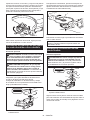
Installing or removing wheel guard
(For depressed center wheel, ap disc,
ex wheel, wire wheel brush / abrasive
cut-o wheel, diamond wheel)
WARNING: When using a depressed center
wheel, ap disc, ex wheel or wire wheel brush,
the wheel guard must be tted on the tool so that
the closed side of the guard always points toward
the operator.
WARNING: When using an abrasive cut-o
/ diamond wheel, be sure to use only the special
wheel guard designed for use with cut-o wheels.
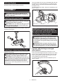
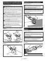
For tool with locking screw type
wheel guard
Mount the wheel guard with the protrusions on the
wheel guard band aligned with the notches on the bear-
ing box. Then rotate the wheel guard to such an angle
that it can protect the operator according to work. Be
sure to tighten the screw securely.
To remove wheel guard, follow the installation proce-
dure in reverse.
1
2
3
► 1. Wheel guard 2. Bearing box 3. Screw

9ENGLISH
For tool with clamp lever type wheel
guard
Optional accessory
WARNING: The wheel guard must be tted
on the tool so that the closed side of the guard
always points toward the operator.
Loosen the nut, and then pull the lever in the direction
of the arrow.
1
2
► 1. Nut 2. Lever
Mount the wheel guard with the protrusions on the
wheel guard band aligned with the notches on the bear-
ing box. Then rotate the wheel guard to such an angle
that it can protect the operator according to work.
1
2
► 1. Wheel guard 2. Bearing box
1
► 1. Wheel guard
Securely tighten the nut using a spanner, and then
close the lever in direction of the arrow to fasten the
wheel guard. If the lever is too tight or too loose to
fasten the wheel guard, open the lever and then loosen
or tighten the nut using the spanner to adjust the tight-
ening of the wheel guard band.
21
► 1. Nut 2. Lever
To remove wheel guard, follow the installation proce-
dure in reverse.
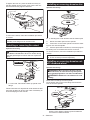
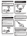
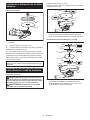
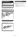
Installing or removing depressed
center wheel or ap disc
Optional accessory
WARNING: When using a depressed center
wheel or ap disc, the wheel guard must be tted
on the tool so that the closed side of the guard
always points toward the operator.
CAUTION: Make sure that the mounting part
of the inner ange ts into the inner diameter of
the depressed center wheel / ap disc perfectly.
Mounting the inner ange on the wrong side may
result in the dangerous vibration.
Mount the inner ange onto the spindle.
Make sure to t the dented part of the inner ange onto
the straight part at the bottom of the spindle.
Fit the wheel / disc on the inner ange and screw the
lock nut with its protrusion facing downward (facing
towards the wheel).
3
2
1
► 1. Lock nut 2. Depressed center wheel 3. Inner
ange

10 ENGLISH
To tighten the lock nut, press the shaft lock rmly so
that the spindle cannot revolve, then use the lock nut
wrench and securely tighten clockwise.
2
1
► 1. Lock nut wrench 2. Shaft lock
To remove the wheel, follow the installation procedure
in reverse.
NOTE: In countries other than United States and
Canada, Inner ange 45 can be also used.
Installing or removing ex wheel
Optional accessory
WARNING: Always use supplied guard when
ex wheel is on the tool. Wheel can shatter during
use and guard helps to reduce chances of personal
injury.
4
3
2
1
► 1. Lock nut 2. Flex wheel 3. Back up pad 4. Inner
ange
Follow instructions for depressed center wheel but also
use back up pad over wheel. See order of assembly on
accessories page in this manual.
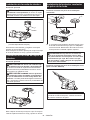
Installing or removing abrasive disc
Optional accessory
3
2
1
► 1. Sanding lock nut 2. Abrasive disc 3. Rubber pad
1. Mount the rubber pad onto the spindle.
2. Fit the disc on the rubber pad and screw the sand-
ing lock nut onto the spindle.
3.
Hold the spindle with the shaft lock, and securely tighten
the sanding lock nut clockwise with the lock nut wrench.
To remove the disc, follow the installation procedure in
reverse.
NOTE: Use sander accessories specied in this man-
ual. These must be purchased separately.
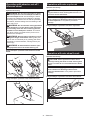
Installing or removing abrasive cut-
o / diamond wheel
Optional accessory
WARNING: When using an abrasive cut-o
/ diamond wheel, be sure to use only the special
wheel guard designed for use with cut-o wheels.
WARNING: NEVER use cut-o wheel for side
grinding.
Mount the inner ange onto the spindle.
Fit the wheel / disc on the inner ange and screw the
lock nut onto the spindle.
3
4
2
1
► 1. Lock nut 2. Abrasive cut-o wheel / diamond
wheel 3. Inner ange 4. Wheel guard for abrasive
cut-o wheel / diamond wheel

11 ENGLISH
For United States and Canada
ø45
ø78
ø78
1
2
3
4
5
► 1. Lock nut 2. Outer ange 78 3. Abrasive cut-o
wheel / diamond wheel 4. Inner ange 78 5. Wheel
guard for abrasive cut-o wheel / diamond wheel
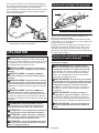
Installing wire cup brush
Optional accessory
CAUTION: Do not use brush that is damaged,
or which is out of balance. Use of damaged brush
could increase potential for injury from contact with
broken brush wires.
1
2
► 1. Wire cup brush 2. Urethane washer (included
depending on the country)
Unplug tool and place it upside down allowing easy
access to spindle.
Remove any accessories on spindle. Thread wire cup
brush onto spindle and tighten with the wrench.
Installing wire wheel brush
Optional accessory
CAUTION: Do not use wire wheel brush that
is damaged, or which is out of balance. Use of
damaged wire wheel brush could increase potential
for injury from contact with broken wires.
CAUTION: ALWAYS use guard with wire
wheel brushes, assuring diameter of wheel ts
inside guard. Wheel can shatter during use and
guard helps to reduce chances of personal injury.
1
► 1. Wire wheel brush
Remove any accessories on spindle. Thread wire wheel
brush onto spindle and tighten with the wrench.
Installing dust collecting wheel
guard
Dust collecting wheel guard for grinding
1
2
4
5
6
3
► 1. Lock nut 2. Cup-type diamond wheel 3. Hubbed
cup-type diamond wheel 4. Inner ange 5. Dust
collecting wheel guard 6. Bearing box
WARNING: Dust collecting wheel guard for
grinding is only for use in grinding at concrete
with a cup-type diamond wheel. Do not use it with
grinding stones or for any purpose other than
mentioned.

12 ENGLISH
Dust collecting wheel guard for cut-o (for model
GA9070)
NOTE: For information how to install the dust collect-
ing cover, refer to the manual of the dust collecting
cover.
Connecting a vacuum cleaner
Optional accessory
WARNING: Never vacuum metal particles
generated by operation. Metal particles generated
by such operation are so hot that they ignite dust and
the lter inside the vacuum cleaner.
To avoid dusty environment caused by masonry cut-
ting, use a dust collecting wheel guard and a vacuum
cleaner.
Refer to the instruction manual attached to the dust
collecting wheel guard for assembling and using it.
1
2
► 1. Dust collecting wheel guard for cut-o 2. Hose of
the vacuum cleaner
OPERATION
WARNING: It should never be necessary to
force the tool. The weight of the tool applies ade-
quate pressure. Forcing and excessive pressure
could cause dangerous wheel breakage.
WARNING: ALWAYS replace wheel if tool is
dropped while grinding.
WARNING: NEVER bang or hit grinding disc
or wheel onto work.
WARNING: Avoid bouncing and snagging
the wheel, especially when working corners,
sharp edges etc. This can cause loss of control and
kickback.
WARNING: NEVER use tool with wood cutting
blades and other saw blades. Such blades when
used on a grinder frequently kick and cause loss of
control leading to personal injury.
CAUTION: Never switch on the tool when it
is in contact with the workpiece, it may cause an
injury to operator.
CAUTION: Always wear safety goggles or a
face shield during operation.
CAUTION: After operation, always switch o
the tool and wait until the wheel has come to a
complete stop before putting the tool down.
CAUTION: ALWAYS hold the tool rmly with
one hand on housing and the other on the side
grip (handle).
Grinding and sanding operation
Turn the tool on and then apply the wheel or disc to the
workpiece.
In general, keep the edge of the wheel or disc at an
angle of about 15° to the workpiece surface.
During the break-in period with a new wheel, do not
work the grinder in forward direction or it may cut into
the workpiece. Once the edge of the wheel has been
rounded o by use, the wheel may be worked in both
forward and backward direction.

13 ENGLISH
Operation with abrasive cut-o /
diamond wheel
Optional accessory
WARNING: Do not "jam" the wheel or apply
excessive pressure. Do not attempt to make an
excessive depth of cut. Overstressing the wheel
increases the loading and susceptibility to twisting
or binding of the wheel in the cut and the possibility
of kickback, wheel breakage and overheating of the
motor may occur.
WARNING: Do not start the cutting operation
in the workpiece. Let the wheel reach full speed
and carefully enter into the cut moving the tool
forward over the workpiece surface. The wheel
may bind, walk up or kickback if the power tool is
started in the workpiece.
WARNING: During cutting operations, never
change the angle of the wheel. Placing side pres-
sure on the cut-o wheel (as in grinding) will cause
the wheel to crack and break, causing serious per-
sonal injury.
WARNING: A diamond wheel shall be oper-
ated perpendicular to the material being cut.
Usage example: operation with abrasive cut-o
wheel
Usage example: operation with diamond wheel
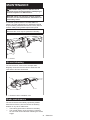
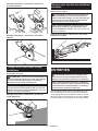
Operation with wire cup brush
Optional accessory
CAUTION: Check operation of brush by run-
ning tool with no load, insuring that no one is in
front of or in line with brush.
NOTICE: Avoid applying too much pressure
which causes over bending of wires when using
the wire cup brush. It may lead to premature
breakage.
Usage example: operation with wire cup brush
Operation with wire wheel brush
Optional accessory
CAUTION: Check operation of wire wheel
brush by running tool with no load, insuring that
no one is in front of or in line with the wire wheel
brush.
NOTICE: Avoid applying too much pressure
which causes over bending of wires when
using wire wheel brush. It may lead to premature
breakage.
Usage example: operation with wire wheel brush

14 ENGLISH
MAINTENANCE
CAUTION: Always be sure that the tool is
switched o and unplugged before attempting to
perform inspection or maintenance.
NOTICE: Never use gasoline, benzine, thinner,
alcohol or the like. Discoloration, deformation or
cracks may result.
To maintain product SAFETY and RELIABILITY,
repairs, any other maintenance or adjustment should
be performed by Makita Authorized or Factory Service
Centers, always using Makita replacement parts.
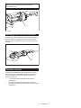
NOTE: Do not loosen the screw on the cover.
Otherwise the cover may be opened accidentally.
1
► 1. Screw
Air vent cleaning
The tool and its air vents have to be kept clean.
Regularly clean the tool's air vents or whenever the
vents start to become obstructed.
1
2
► 1. Exhaust vent 2. Inhalation vent
Brake maintenance
The tool should be immediately repaired by Makita
Authorized or Factory Service Centers in following
situation or any other malfunction;
— The braking performance declines noticeably.
— The inertial rotation of the accessory continues
for more than 6 seconds after releasing the switch
trigger.

15 ENGLISH
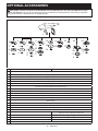
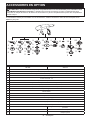
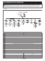
OPTIONAL ACCESSORIES
CAUTION: These accessories or attachments are recommended for use with your Makita tool spec-
ied in this manual. The use of any other accessories or attachments might present a risk of injury to persons.
Only use accessory or attachment for its stated purpose.
If you need any assistance for more details regarding these accessories, ask your local Makita Service Center.
1
2
3
5
4
6
33
8
59
7
8
5
6
11
10
5
12
13
14
21
19
20
5
18 22
3
23
5
22
15
16
17
-180 mm 230 mm
1Side grip / Loop handle
2Wheel guard for depressed center grinding wheel / ap disc / wire wheel brush
3Inner ange 45 / Inner ange 89 *1
4Depressed center grinding wheel / Flap disc
5Lock nut 5/8 - 45
6Wheel guard for abrasive cut o wheel / diamond wheel
7Inner ange 78 (United States and Canada only)*2
8Abrasive cut-o wheel / Diamond wheel
9Outer ange 78 (United States and Canada only) *2
10 Back up pad
11 Flex wheel
12 Rubber pad
13 Abrasive disc
14 Sanding lock nut
15 Wire wheel brush
16 Urethane washer 14 (included depending on the country)
17 Wire cup brush
18 -Side grip for dust collecting wheel guard
19 -Dust collecting wheel guard for cut-o
20 -Special ange
21 -Diamond wheel
22 Dust collecting wheel guard for oset diamond wheel

16 ENGLISH
-180 mm 230 mm
23 Oset diamond wheel
-Lock nut wrench
-Dust cover attachment
NOTE: *1 In countries other than United States and Canada, Inner ange 45 can be also used.
NOTE: *2 Use inner ange 78 and outer ange 78 together (United States and Canada only).
NOTE: Some items in the list may be included in the tool package as standard accessories. They may dier from
country to country.
MAKITA LIMITED WARRANTY
Please refer to the annexed warranty sheet for the
most current warranty terms applicable to this product.
If annexed warranty sheet is not available, refer to the
warranty details set forth at below website for your
respective country.
United States of America: www.makitatools.com
Canada: www.makita.ca
Other countries: www.makita.com

17 FRANÇAIS
FRANÇAIS (Mode d’emploi original)
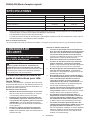
SPÉCIFICATIONS
Modèle : GA7070 GA9070
Diamètre de la meule 180 mm (7″) 230 mm (9″)
Épaisseur de meule max. 7,2 mm (9/32″) 6,5 mm (1/4″)
Filetage de l’arbre 5/8″
Vitesse nominale (n) 8 500 /min 6 600 /min
Longueur totale 506 mm (20″)
Poids net 6,1 - 6,6 kg (13,4 - 14,6 lbs) 6,3 - 8,5 kg (13,9 - 18,7 lbs)
• Étant donné l’évolution constante de notre programme de recherche et de développement, les spécications
contenues dans ce manuel sont sujettes à modication sans préavis.
• Les spécications peuvent varier suivant les pays.
• Le poids peut varier suivant les accessoires. La plus légère et la plus lourde des combinaisons, selon la procé-
dure EPTA 01/2014, sont indiquées dans le tableau.
Pour le Canada uniquement
* Si vous installez sur l’outil un protecteur de meule 7″ en option, les meules de 180 mm (7″) pourront être utilisées.
CONSIGNES DE
SÉCURITÉ
Consignes de sécurité générales
pour outils électriques
MISE EN GARDE : Veuillez lire toutes les
mises en garde, instructions, illustrations et
spécications qui accompagnent cet outil élec-
trique. Ne pas suivre toutes les instructions de la liste
ci-dessous peut entraîner une décharge électrique,
un incendie et/ou une grave blessure.
Conservez toutes les mises en
garde et instructions pour réfé-
rence future.
Le terme « outil électrique » qui gure dans les avertis-
sements fait référence à un outil électrique branché sur
une prise de courant (par un cordon d’alimentation) ou
alimenté par batterie (sans l).
Sécurité de la zone de travail
1.
Maintenez la zone de travail propre et bien éclai-
rée. Les zones de travail encombrées ou sombres
ouvrent toute grande la porte aux accidents.
2. N’utilisez pas les outils électriques dans les
atmosphères explosives, telles que celles où
sont présents des liquides, gaz ou poussières
inammables. Les outils électriques génèrent
des étincelles qui peuvent allumer les poussières
ou les vapeurs.
3. Gardez les enfants et personnes présentes
à l’écart pendant l’utilisation d’un outil élec-
trique. Toute distraction peut vous faire perdre la
maîtrise de l’outil.
Sécurité en matière d’électricité
1.
Les ches d’outil électrique doivent correspondre à la
prise de courant. Ne modiez jamais la che, de quelque
façon que ce soit. N’utilisez aucune che d’adaptation
avec les outils électriques mis à la terre (à la masse).
Les ches non modiées et les prises de courant correspon-
dantes réduisent le risque de décharge électrique.
2. Évitez tout contact avec les surfaces mises
à la terre ou à la masse, telles que celles des
tuyaux, radiateurs, cuisinières et réfrigéra-
teurs. Le risque de décharge électrique augmente
si votre corps est mis à la terre ou à la masse.
3. N’exposez pas les outils électriques à la pluie
ou à des surfaces mouillées. La pénétration
d’eau dans un outil électrique augmente le risque
de décharge électrique.
4. Ne maltraitez pas le cordon. N’utilisez jamais
le cordon pour transporter, tirer sur ou débran-
cher l’outil électrique. Gardez le cordon à
l’écart de la chaleur, de l’huile, des bords
tranchants ou des pièces en mouvement. Les
cordons endommagés ou enchevêtrés augmen-
tent le risque de décharge électrique.
5.
Lorsque vous utilisez un outil électrique à l’extérieur,
faites-le avec un cordon prolongateur conçu pour
l’usage extérieur. Utiliser un cordon conçu pour l’usage
extérieur réduit le risque de décharge électrique.
6.
Si l’utilisation d’un outil électrique dans un
emplacement humide est inévitable, utilisez une
source d’alimentation protégée par un disjonc-
teur diérentiel de fuite à la terre (DDFT). Utiliser
un DDFT réduit le risque de décharge électrique.
7. Les outils électriques peuvent produire des
champs électromagnétiques (CEM) qui ne sont
pas préjudiciables à l’utilisateur. Les utilisa-
teurs de stimulateur cardiaque ou autres appareils
médicaux similaires doivent toutefois demander
conseil au fabricant et/ou à leur médecin avant
d’utiliser cet outil électrique.

18 FRANÇAIS
8. Ne touchez pas la che d’alimentation avec les
mains mouillées.
9. Si le cordon est endommagé, faites-le rempla-
cer par le fabricant ou son représentant, pour
éviter les risques d’accident.
Sécurité personnelle
1.
Restez vigilant, attentif à vos gestes et faites
preuve de bon sens pendant l’utilisation d’un
outil électrique. N’utilisez pas un outil électrique
lorsque vous êtes fatigué ou sous l’inuence
d’une drogue, de l’alcool ou d’un médicament.
Tout moment d’inattention pendant l’utilisation des
outils électriques peut entraîner une grave blessure.
2.
Utilisez l’équipement de protection individuel.
Portez toujours un protecteur pour la vue. Utilisé
dans les conditions adéquates, l’équipement de
protection - masque antipoussière, chaussures de
sécurité antidérapantes, casque de protection ou
protecteur auditif - réduit le risque de blessures.
3. Évitez le démarrage accidentel. Assurez-vous
que l’interrupteur est sur la position d’arrêt
avant de connecter la source d’alimentation et/
ou la batterie, de saisir l’outil ou de le trans-
porter. Transporter les outils électriques avec le
doigt sur l’interrupteur, ou les connecter à une
source d’alimentation alors que l’interrupteur est
en position de marche ouvre toute grande la porte
aux accidents.
4. Retirez toute clé de serrage ou de réglage
avant de mettre l’outil électrique en marche.
Une clé laissée en place sur une pièce rotative de
l’outil électrique peut entraîner une blessure.
5. Ne vous étirez pas trop. Assurez-vous d’une
bonne prise au sol et d’une bonne position
d’équilibre en tout temps. Cela procure une
meilleur maîtrise de l’outil électrique dans les
situations imprévues.
6.
Portez des vêtements adéquats. Ne portez ni
vêtements amples ni bijoux. Gardez vos cheveux,
vêtements et gants à l’écart des pièces en mouve-
ment. Les vêtements amples, bijoux ou cheveux longs
peuvent être happés par les pièces en mouvement.
7. Si des accessoires sont fournis pour raccor-
der un appareil d’aspiration et de collecte
des poussières, assurez-vous qu’ils sont
correctement raccordés et qu’ils sont utilisés
de manière adéquate. L’utilisation d’un appareil
de collecte des poussières permet de réduire les
risques liés à la présence de poussières dans l’air.
8. Ne vous laissez pas abuser, au point d’être sûr
de vous et d’ignorer les principes de sécurité,
par un sentiment de familiarité acquis par l’uti-
lisation fréquente des outils électriques. Un
geste irrééchi peut entraîner une grave blessure
en une fraction de seconde.
9. Portez toujours des lunettes à coques de pro-
tection pour protéger vos yeux contre les bles-
sures lors de l’utilisation d’outils électriques.
Les lunettes à coques doivent être conformes
à ANSI Z87.1 aux États-Unis.
L’employeur a la responsabilité d’imposer
l’utilisation d’équipements de protection de
sécurité adéquats aux utilisateurs des outils
électriques et à toute autre personne se trou-
vant dans la zone de travail immédiate.
Utilisation et entretien des outils électriques
1. Ne forcez pas l’outil électrique. Utilisez l’outil
électrique qui convient à votre application. Si
vous utilisez l’outil électrique adéquat et respectez
le régime pour lequel il a été conçu, il eectuera
un travail de meilleure qualité et plus sécuritaire.
2.
N’utilisez pas l’outil électrique s’il n’est pas pos-
sible de l’allumer et de l’éteindre avec son inter-
rupteur. Tout outil électrique dont l’interrupteur est
défectueux représente un danger et doit être réparé.
3.
Débranchez la che de la source d’alimentation
et/ou retirez la BATTERIE de l’outil électrique, si
elle est amovible, avant d’eectuer tout réglage,
de remplacer les accessoires ou de ranger les
outils électriques. De telles mesures de sécurité
préventives réduisent le risque de démarrage
accidentel de l’outil électrique.
4. Mettez les outils électriques sous tension
hors de la portée des enfants et ne laissez
aucune personne les utiliser si elle n’est pas
familiarisée avec l’outil électrique ou avec les
présentes instructions d’utilisation. Les outils
électriques représentent un danger entre les
mains de personnes qui n’en connaissent pas le
mode d’utilisation.
5. Veillez à l’entretien des outils électriques et
des accessoires. Assurez-vous que les pièces
mobiles ne sont pas désalignées ou coincées,
qu’aucune pièce n’est cassée et que l’outil
électrique n’a subi aucun dommage aectant
son bon fonctionnement. Si un outil électrique
est endommagé, faites-le réparer avant de
l’utiliser. De nombreux accidents sont causés par
des outils électriques mal entretenus.
6. Maintenez les outils tranchants bien aiguisés
et propres. Les outils tranchants dont l’entretien
est eectué correctement et dont les bords sont
bien aiguisés risquent moins de se coincer et sont
plus faciles à maîtriser.
7. Utilisez l’outil électrique, ses accessoires, ses
embouts, etc., en respectant les présentes
instructions et en tenant compte des condi-
tions de travail et du type de travail à eectuer.
L’utilisation d’un outil électrique pour d’autres
usages que ceux prévus peut entraîner une situa-
tion dangereuse.
8. Gardez les poignées et surfaces de saisie
sèches, propres et exemptes d’huile et de
graisse. Les poignées et surfaces de saisie glis-
santes ne permettent pas la manipulation sécu-
ritaire et une bonne maîtrise de l’outil dans les
situations imprévues.
9. Lors de l’utilisation de l’outil, ne portez pas
de gants de travail en tissu qui risquent de
s’enchevêtrer dans l’outil. L’enchevêtrement de
gants de travail en tissu dans les pièces en mou-
vement peut entraîner une blessure.
Réparation
1. Faites réparer votre outil électrique par un
réparateur qualié qui utilise des pièces de
rechange identiques aux pièces d’origine. Le
maintien de la sûreté de l’outil électrique sera ainsi
assuré.
2. Suivez les instructions de lubrication et de
remplacement des accessoires.

19 FRANÇAIS
Pour réduire le risque de décharge électrique, cet équi-
pement est doté d’une che polarisée (une des lames
est plus large que l’autre). Cette che ne s’insère que
dans un seul sens dans une prise de courant polari-
sée. Si la che ne pénètre pas à fond dans la prise de
courant, insérez-la dans l’autre sens. Si elle ne s’insère
toujours pas à fond, contactez un électricien qualié
pour faire installer une prise de courant adéquate. Ne
modiez la che d’aucune façon.
MISE EN GARDE SUR LA TENSION : Avant de bran-
cher l’outil sur une source d’alimentation (prise murale,
prise de courant, etc.), assurez-vous que la tension
fournie est la même que celle spéciée sur la plaque
signalétique de l’outil. Une source d’alimentation dont
la tension est supérieure à celle spéciée pour l’outil
peut entraîner une GRAVE BLESSURE pour l’utilisa-
teur, ainsi qu’endommager l’outil. En cas de doute, NE
BRANCHEZ PAS L’OUTIL. L’utilisation d’une source
d’alimentation dont la tension est inférieure à celle
indiquée sur la plaque signalétique endommagera le
moteur.
UTILISEZ UN CORDON PROLONGATEUR
APPROPRIÉ. Assurez-vous que votre cordon prolon-
gateur est en bonne condition. Lorsque vous utilisez
un cordon prolongateur, assurez-vous qu’il est assez
robuste pour transporter le courant exigé par le produit.
Un cordon trop petit entraînera une baisse dans la
tension composée, ce qui causera une perte d’énergie
et une surchaue. Le tableau 1 indique la dimension de
cordon à utiliser, en fonction de la longueur du cordon
et de l’intensité nominale gurant sur la plaque signalé-
tique. En cas de doute, utilisez un calibre plus robuste.
Plus le numéro de calibre est bas, plus le cordon est
robuste.
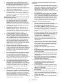
Tableau 1 : Calibre minimum du cordon
Intensité nominale Volts Longueur totale du cordon en pieds
120 V 25 ft. 50 ft. 100 ft. 150 ft.
220 V - 240 V 50 ft. 100 ft. 200 ft. 300 ft.
Plus de Pas plus de Calibre américain des ls
0 A 6 A –18 16 16 14
6 A 10 A 18 16 14 12
10 A 12 A 16 16 14 12
12 A 16 A 14 12 Non recommandé
Consignes de sécurité pour
meuleuse
Consignes de sécurité communes aux travaux de
meulage, ponçage, brossage métallique et tronçon-
nage abrasif :
1. Cet outil électrique est conçu pour fonc-
tionner en tant que meuleuse, ponceuse,
brosse métallique ou outil de tronçonnage.
Lisez toutes les mises en garde, instructions,
illustrations et spécications qui accom-
pagnent cet outil électrique. Il y a risque de
décharge électrique, d’incendie et/ou de blessure
grave si les instructions ci-dessous ne sont pas
respectées.
2. Il n’est pas recommandé d’eectuer des tra-
vaux tels que le polissage avec cet outil élec-
trique. Les travaux pour lequel l’outil électrique
n’a pas été conçu peuvent engendrer un danger et
causer des blessures.
3. N’utilisez pas d’accessoires non conçus spé-
ciquement pour l’outil et non recommandés
par le fabricant de l’outil. Même si un accessoire
peut être xé à votre outil électrique, cela ne
garantit pas son fonctionnement sécuritaire.
4. La vitesse nominale de l’accessoire doit être
au moins égale à la vitesse maximale inscrite
sur l’outil électrique. En tournant plus vite que
leur vitesse nominale, les accessoires peuvent
casser et voler en éclats.
5.
Le diamètre extérieur et l’épaisseur de votre
accessoire ne doivent pas dépasser la capacité
nominale de votre outil électrique. Il est impos-
sible de protéger ou de contrôler adéquatement les
accessoires d’une dimension inappropriée.
6. Le montage leté des accessoires doit corres-
pondre au letage de l’arbre de la meuleuse.
Pour les accessoires montés à l’aide de
asques, le diamètre intérieur de l’accessoire
doit correspondre au diamètre de positionne-
ment du asque. Les accessoires non adaptés
aux pièces de montage de l’outil électrique se
déséquilibreront, vibreront excessivement et
risqueront d’entraîner une perte de contrôle.
7.
N’utilisez pas un accessoire endommagé. Avant
chaque utilisation, inspectez les accessoires
pour vérier l’absence de copeaux et ssures
sur les accessoires tels que les meules abra-
sives, l’absence de ssures ou d’usure exces-
sive sur le tampon d’appoint, et l’absence de ls
lâches ou ssurés sur la brosse métallique. Si
vous échappez l’outil électrique ou un acces-
soire, assurez-vous de l’absence de dommages
ou installez un accessoire non endommagé.
Après avoir vérié et installé un accessoire,
assurez-vous que personne, y compris vous-
même, ne se trouve dans la trajectoire de
l’accessoire en rotation, et faites tourner l’outil
électrique à vide et à vitesse maximale pendant
une minute. Si l’accessoire est endommagé, il
devrait normalement se casser pendant cet essai.

20 FRANÇAIS
8. Portez des dispositifs de sécurité personnelle.
Suivant le type d’utilisation, portez un écran
facial, des lunettes à coques ou des lunettes
de sécurité. Au besoin, portez un masque
antipoussières, des protections d’oreilles,
des gants et un tablier de travail assez épais
pour arrêter les petits fragments abrasifs ou
les fragments de pièce. La protection oculaire
utilisée doit pouvoir protéger contre les débris
projetés lors des divers travaux. Le masque anti-
poussières ou le respirateur doit pouvoir ltrer les
particules générées par votre travail. L’exposition
trop longue à un bruit très intense peut entraîner
des lésions de l’ouïe.
9. Tenez toutes les personnes présentes à une
distance sécuritaire de votre zone de travail.
Toute personne pénétrant dans votre zone de
travail doit porter des dispositifs de protection
personnelle. Des fragments de pièce ou d’un
accessoire cassé peuvent s’envoler et blesser
quelqu’un même au-delà de la zone de travail
immédiate.
10. Tenez l’outil électrique uniquement par ses
surfaces de prise isolées pendant tout travail
où l’accessoire de coupe pourrait venir en
contact avec un câblage dissimulé ou avec
son propre cordon. En cas de contact de l’acces-
soire de coupe avec un conducteur sous tension,
les pièces métalliques à découvert de l’outil élec-
trique risqueraient de transmettre une décharge
électrique à l’utilisateur.
11. Positionnez le cordon loin de l’accessoire en
rotation. Si vous perdez la maîtrise de l’outil, le
cordon risque d’être coupé ou accroché, et votre
main ou bras risque d’être entraîné vers l’acces-
soire en rotation.
12. Ne reposez jamais l’outil électrique tant que
l’accessoire ne s’est pas complètement immo-
bilisé. L’accessoire en rotation risquerait d’accro-
cher la surface et d’entraîner la perte de maîtrise
de l’outil électrique.
13. Ne faites pas fonctionner l’outil électrique
lorsque vous le transportez. Un contact acci-
dentel avec l’accessoire en rotation pourrait accro-
cher vos vêtements et entraîner l’accessoire vers
votre corps.
14. Nettoyez régulièrement les orices d’aération
de l’outil électrique. Le ventilateur du moteur
aspire les poussières à l’intérieur du boîtier, et
l’accumulation excessive de métal en poudre peut
entraîner un risque électrique.
15. N’utilisez pas l’outil électrique près de maté-
riaux inammables. Les étincelles risqueraient
de faire prendre en feu ces matériaux.
16. N’utilisez pas d’accessoires qui requièrent un
liquide de refroidissement. L’utilisation d’eau
ou autre liquide de refroidissement peut entraîner
une électrocution ou une décharge électrique.
Recul et mises en gardes connexes
Le recul est une réaction brusque qui se produit lors-
qu’une meule en rotation, un tampon d’appoint, une
brosse ou autre accessoire se coince ou accroche. Le
coincement ou l’accrochage entraîne l’arrêt rapide de
l’accessoire en rotation, ce qui en retour propulse l’outil
électrique hors de contrôle dans le sens opposé à la
rotation de l’accessoire au point de grippage.
Par exemple, si une meule abrasive accroche dans la
pièce ou s’y coince, le bord de la meule, au point où elle
se coince, plongera dans le matériau, faisant du même
coup remonter ou reculer la meule hors de la pièce.
La meule peut alors bondir vers l’utilisateur ou dans
le sens opposé, selon la direction du mouvement de
la meule au point de coinçage. Les meules abrasives
peuvent également se casser dans ces conditions.
Le recul est le résultat d’une mauvaise utilisation de
l’outil électrique et/ou de mauvaises méthodes ou
conditions d’utilisation ; on peut l’éviter en prenant les
précautions adéquates indiquées ci-dessous.
1.
Maintenez une prise ferme sur l’outil électrique,
et placez votre corps et votre bras de manière à
pouvoir résister aux forces de recul. Utilisez tou-
jours la poignée auxiliaire, le cas échéant, pour
contrôler au maximum le recul ou la réaction de
couple durant le démarrage. Si les précautions
adéquates sont prises, l’utilisateur peut contrôler les
réactions de couple ou les forces de recul.
2. Ne mettez jamais votre main près de l’acces-
soire en rotation. L’accessoire pourrait reculer
sur votre main.
3. Ne placez pas votre corps dans la zone où
l’outil électrique se déplacera en cas de recul.
Le recul propulsera l’outil dans le sens opposé au
mouvement de la meule au point d’accrochage.
4. Soyez tout particulièrement prudent lorsque
vous travaillez dans les coins, sur les rebords
aigus, etc. Évitez de faire bondir ou accrocher
l’accessoire. Les coins, les rebords aigus ou les
rebondissements ont tendance à provoquer un
accrochage de l’accessoire en rotation et à causer
une perte de contrôle ou un recul.
5. Ne xez pas de chaîne de scie, de lame de
sculpture ou de lame de scie dentée. De telles
lames créent fréquemment un recul et une perte
de contrôle.
Consignes de sécurité spéciques aux travaux de
meulage et de tronçonnage abrasif :
1. Utilisez uniquement des meules du type
recommandé pour votre outil électrique, et les
protecteurs spéciquement conçus pour la
meule sélectionnée. Les meules pour lesquelles
l’outil électrique n’a pas été conçu ne peuvent être
adéquatement protégées et sont dangereuses.
2. La surface de meulage des meules à moyeu
déporté doit être montée sous le plan de la
lèvre du protecteur. Une meule mal montée qui
dépasse le plan de la lèvre ne peut être adéquate-
ment protégée.
3.
Le protecteur doit être solidement xé à l’outil
électrique et positionné pour un maximum de
sécurité, an qu’un minimum de meule soit
exposé vers l’utilisateur. Le protecteur aide à
protéger l’utilisateur des fragments cassés de
meule, d’un contact accidentel avec la meule et des
étincelles qui peuvent mettre feu aux vêtements.
4. Les meules ne doivent être utilisées que pour
les applications recommandées. Exemple :
ne meulez pas avec le côté de la meule tron-
çonneuse. Les meules tronçonneuses abrasives
sont conçues pour le meulage périphérique. Elles
peuvent voler en éclats sous l’eet d’une force
latérale.
La page est en cours de chargement...
La page est en cours de chargement...
La page est en cours de chargement...
La page est en cours de chargement...
La page est en cours de chargement...
La page est en cours de chargement...
La page est en cours de chargement...
La page est en cours de chargement...
La page est en cours de chargement...
La page est en cours de chargement...
La page est en cours de chargement...
La page est en cours de chargement...
La page est en cours de chargement...
La page est en cours de chargement...
La page est en cours de chargement...
La page est en cours de chargement...
La page est en cours de chargement...
La page est en cours de chargement...
La page est en cours de chargement...
La page est en cours de chargement...
La page est en cours de chargement...
La page est en cours de chargement...
La page est en cours de chargement...
La page est en cours de chargement...
La page est en cours de chargement...
La page est en cours de chargement...
La page est en cours de chargement...
La page est en cours de chargement...
La page est en cours de chargement...
La page est en cours de chargement...
La page est en cours de chargement...
La page est en cours de chargement...
-
 1
1
-
 2
2
-
 3
3
-
 4
4
-
 5
5
-
 6
6
-
 7
7
-
 8
8
-
 9
9
-
 10
10
-
 11
11
-
 12
12
-
 13
13
-
 14
14
-
 15
15
-
 16
16
-
 17
17
-
 18
18
-
 19
19
-
 20
20
-
 21
21
-
 22
22
-
 23
23
-
 24
24
-
 25
25
-
 26
26
-
 27
27
-
 28
28
-
 29
29
-
 30
30
-
 31
31
-
 32
32
-
 33
33
-
 34
34
-
 35
35
-
 36
36
-
 37
37
-
 38
38
-
 39
39
-
 40
40
-
 41
41
-
 42
42
-
 43
43
-
 44
44
-
 45
45
-
 46
46
-
 47
47
-
 48
48
-
 49
49
-
 50
50
-
 51
51
-
 52
52


Makita GA7070 Manuel utilisateur
- Catégorie
- Outils électroportatifs
- Taper
- Manuel utilisateur
- Ce manuel convient également à
dans d''autres langues
- English: Makita GA7070 User manual
- español: Makita GA7070 Manual de usuario