Küppersbusch IKD18560.0 Instructions For Use And Installation Instructions
- Catégorie
- Hottes
- Taper
- Instructions For Use And Installation Instructions

IKD15560.0 - IKD18560.0
BEDIENUNGSANWEISUNG
mit Montageanweisungen
GB
Instructions for use and installation instructions
Instructions d'utilisation et avis de montage
Gebruiksaanwijzing en montagehandleiding
Istruzioni di uso e di montaggio
Instrucciones de uso y de montaje
Instruções de uso e de montagem
F
NL
I
E
P

vorgegebenen Geschwindigkeit ein. Drückt man diese Taste während der Anzeige des ALARM FILTER, so erzielt
man die Rückstellung (RESET) des Zählwerks der Betriebsstunden, das in der Folge neu anläuft. Taste E:
Erhöhen der Motorgeschwindigkeit. Nach etwa 1 Minute schaltet die Haube automatisch wieder auf die vom
Sensor vorgegebene Geschwindigkeit um.
Einstellen der Sensorsensibilität: Die Sensibilität des Sensors kann folgendermaßen eingestellt werden:
- Die Haube durch Drücken der Taste B ausschalten. Gleichzeitig die Tasten D und E drücken (auf dem Display
erscheint die Anzeige der Sensorsensibilität). Taste D oder E drücken, um die Sensibilität des Sensors zu
erhöhen bzw. zu vermindern (1: geringste Sensibilität / 9: höchste Sensibilität). - Bei einem Stromausfall stellt
sich der Sensor automatisch auf Sensibilitätsstufe 5 ein.
Achtung: Verwenden Sie in der Nähe der Haube keine Silikonprodukte, weil diese den Sensor beschädigen
könnten!
BETRIEB ALS HERKÖMMLICHE ABZUGSHAUBE:
Taste A: Ein- und Ausschalten der Lampen. Display C: - Zeigt die gewählte Motorgeschwindigkeit an (von
1 bis 4); das Blinken der Zahl zeigt den Betrieb des Timers an. Das Einschalten bzw. Blinken des mittleren
Teiles deutet auf einen Filteralarm hin. Taste D: Vermindern der Motorgeschwindigkeit / Anhalten / Reset. Die
Motorgeschwindigkeit wird bis auf Null vermindert (Anhalten). Drückt man diese Taste während der Anzeige des
Filteralarms, so erzielt man die Rückstellung (RESET) des Zählwerks der Betriebsstunden, das neu anläuft. Taste
E: Einschalten des Motors / Erhöhen der Motorgeschwindigkeit / TIMER. Durch Drücken dieser Taste wird der
Motor eingeschaltet (mit der letzten gewählten Geschwindigkeit). Durch erneutes Drücken erhöht man die
Motorgeschwindigkeit. Hält man die Taste einige Sekunden lang gedrückt, so aktiviert man den TIMER, durch
den der Motor nach 5 Minuten angehalten wird (gleichzeitig blinkt auf dem Display die der gewählten Geschwindigkeit
entsprechende Nummer). Der Timer bleibt bei Ändern der Motorgeschwindigkeit in Betrieb und kann durch
erneutes Drücken der Taste ausgeschaltet werden.
Fettfilter: Die Fettfilter müssen in regelmäßigen Abständen sorgfältig gereinigt werden. Auf der Haube wird durch
den “Alarm Filter” angezeigt, wann eine Reinigung der Fettfilter erforderlich ist (nach etwa 30 Betriebsstunden). Die
Fettfilter sind in jedem Fall, abhängig vom Gebrauch, durchschnittlich alle 2 Monate zu reinigen. Entfernung der Filter:
Den Halter in der Nähe des Griffs nach innen drücken und den Filter nach unten ziehen (Abb. 3). Die Filter mit einem
neutralen Reiniger waschen.
Kohlefilter: Wird die Haube als Umluftversion installiert und verwendet, so müssen in regelmäßigen Zeitabständen
die Kohlefilter ersetzt werden. Auf der Haube wird durch den “Alarm Filter” angezeigt, wann diese ersetzt werden müssen
(nach etwa 120 Betriebsstunden). Diese geschieht durch Blinken des mittleren Teiles des Displays (C). Die Kohlefilter
sind in jedem Fall, abhängig vom Gebrauch, durchschnittlich alle 6 Monate zu ersetzen. Ersatz der Kohlefilter: Den
Festhalter nach innen drücken (Abb. 18) und nach unten drehen, bis die beiden Filterzungen aus ihrem Sitz entfernt werden
können.
Beleuchtung: Abb. 20: Zur Entfernung der Halogenbirnen ist die Fassung entgegen dem Uhrzeigersinn zu drehen.
Setzen Sie Ersatzbirnen desselben Typs ein.
Dieses Elektrohaushaltsgerät ist entsprechend der EU-Richtlinie 2002/96/CE über Elektro- und Elektronik-
Altgeräte (WEEE) gekennzeichnet. Bitte sorgen Sie dafür, dass das Gerät ordnungsgemäß entsorgt wird, damit
mögliche negative Auswirkungen auf Umwelt und Gesundheit vermieden werden, die bei einer unsachgemäßen
Entsorgung des Altgerätes entstehen könnten. Das Symbol auf dem Produkt bedeutet, dass dieses Gerät nicht
in den normalen Hausmüll gehört, sondern den jeweiligen kommunalen Rücknahmesystemen für Elektro- und
Elektronik-Altgeräte übergeben werden muss. Die Entsorgung muss im Einklang mit den geltenden Umweltrichtlinien
für die Abfallentsorgung erfolgen. Für nähere Informationen über Entsorgung und Recycling dieses Produktes
wenden Sie sich bitte an Ihre kommunalen Einrichtungen (Umweltamt) oder an die Abfallentsorgungsgesellschaft
Ihrer Stadt bzw. an Ihren Händler.
ENGLISH
WARNING
The distance between the supporting surface for the cooking vessels on the hob and the lower part of the hood must
be at least 65 cm. If the instructions for installation for the hob specify a greater distance, this has to be taken into
account.
The air collected must not be conveyed into a duct used to blow off smokes from appliances fed with an energy other
than electricity (central heating systems, thermosiphons, water-heaters, etc.).
Comply with the official instructions provided by the competent authorities in merit when installing the disposal duct.
In addition, exhaust air should not be discharged into a wall cavity, unless the cavity is designed for that purpose.
The room must be well aerated in case a hood and some other heat equipment fed with an energy other than electricity

(gas, oil, coal heaters, etc) operate at the same time.
In fact the intake hood, disposing of air, could create a vacuum in the room. The vacuum should not exceed 0,04mbar.
This prevents the gas exhausted by the heat source from being intaken again. It is therefore advisable to ensure
the room contains air taps able to ensure a steady flow of fresh air.
Check the data label inside the appliance; if the symbol ( ) is printed, read the following: this appliance has
such technical particulars that it belongs to class II insulation, therefore it must not be earthed.
The following warning is valid in the United Kingdom only: in case your cable is not furnished with a plug, read the
following instructions; as the colours of the wires in the mains lead of this appliance may not correspond with the
coloured markings identifying the terminals in your plug, proceed as follows: – the wire which is coloured blue must
be connected to the terminal which is marked with the letter N or coloured black; – the wire which is coloured brown
must be connected to the terminal which is marked with the letter L or coloured red. – terminal of a three-pin plug.
Check the data label inside the appliance; if the symbol ( ) is NOT printed, read the following: ATTENTION:
This appliance must be earthed. When making the electrical connections, check that the current socket has a ground
connection.
The following warning is valid in the United Kingdom only: in case your cable is not furnished with a plug, read the
following instructions; as the colours of the wires in the mains lead of this appliance may not correspond with the
coloured markings identifying the terminals in your plug, proceed as follows:
– the wire which is coloured green and yellow must be connected to the terminal in the plug which is marked with the
letter E or by the earth symbol [ ], or coloured green or green and yellow; – the wire which is coloured blue must
be connected to the terminal which is marked with the letter N or coloured black; – the wire which is coloured brown
must be connected to the terminal which is marked with the letter L or coloured red.
When making the electrical connections, check that the voltage values correspond to those indicated on the data
plate inside the appliance itself. In case your appliance is not furnished with a non separating flexible cable and has
no plug, or has not got any other device ensuring omnipolar disconnection from the electricity main, with a contact
opening distance of at least 3 mm, such separating device ensuring disconnection from the main must be included
in the fixed installation. If your unit features a power lead and plug, position this so the plug is accessible.
Always switch off the electricity supply before carrying out any cleaning or servicing operations on the appliance.
USE
Avoid using materials which could cause spurts of flame (flambées) near the appliance.
When frying, take particular care to prevent oil and grease from catching fire. Already used oil is especially dangerous
in this respect. Do not use uncovered electric grates.
To avoid possible risks of fire always comply with the indicated instructions when cleaning anti-grease filters and
when removing grease deposits from the appliance.
MAINTENANCE
Thorough servicing guarantees correct and long-lasting operation.
Any fat deposits should be removed from the appliance periodically depending on amount of use (at least every 2
months). Avoid using abrasive or corrosive products. To clean painted appliances on the outside, use a cloth dipped
in lukewarm water and neutral detergent. To clean steel, copper or brass appliances on the outside, it is always best
to use specific products, following the instructions on the products themselves. To clean the inside of the appliance,
use a cloth (or brush) dipped in denatured ethyl alcohol.
DESCRIPTION
This appliance is equipped with a completely automatic system (Advanced Sensor Control) capable to manage
all the functions of your hood. Thanks to the ASC, the air in the kitchen is costantly clean and odour free
without any manual intervention. The advanced sensor catches all sort of vapours, smokes and odours caused
by the cooking process. The ASC also captures an abnormal presence of GAS.
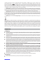
The unit can be found in filtering hoods or in ducting hoods. In the Filtering version the air and the kitchen fumes
that are conveyed by the apparatus are depurated by the charcoal filters and put back into the room through the small
grilles of the ventilation flues (Fig. 1). ATTENTION: When using the filtering version, 2 charcoal filters and an 2 air baffles
(Fig. 1A) must be used, which placed at the top of the structure, allows the air to recycle back into the room. In the Ducting
version, cooking vapours and odours are conveyed straight outside by 2 disposal ducts which pass through the ceiling
(Fig. 2).
INSTALLATION
ATTENTION: Three people are required for proper installation; the unit should be installed by a qualified operator.
Also follow carefully each step of the assembly instructions, and once installation has been completed, make sure
that the hood is firmly secured in place.
To facilitate installation, before starting remove the grease filters: press inward on the clamp at the handle and pull
the filter downward (Fig. 3).
For assembling it is essential to: – Prepare the connection to the mains within the telescopic flues. – If your unit is

installed in a ducting hood, prepare the air exhaust hole.
When installing ducting hoods, to achieve the best possible conditions use an air exhaust pipe that : is as short
as possible, has a minimum of curves (maximum angle: 90°), is made of a material that complies with the standards (which
vary from nation to nation) and is smooth on the inside. It is also advisable to avoid any drastic changes in pipe section
(diameter: 150 mm).
ASSEMBLING - Using the special drilling template, drill the holes for fixing to the ceiling on the vertical side of your
hob. Carefully observe all the indications for final positioning of the apparatus. Take into account that one of the template
axes must correspond to the axis of the hood controls. Fix the brackets to the ceiling using the screws and screw anchors
provided (Fig. 4). Be careful, because the position of the brackets determines the final position of the apparatus: the side
with the slot B corresponds to the side opposite the commands. Assemble the plates of the electrical system fixing it
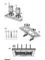
with 6 screws and 4 metal washers (Fig. 5).
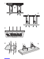
Ducting version: Fix the telescopic structures to the brackets by means of 4+4 screws (provided), running the air evacuation
pipes through the telescopic structures and the electric power cables through the special holes in the brackets (Fig. 6).
Adjust the height of the telescopic structures by means of the 4+4 retaining screws C (Fig. 7), taking into account that
the height of the hood is 80 mm and that the distance between the hood and the hob must be at least 650 mm (Fig. 8).
Take the upper pipes (with the round slots) and fit them on the telescopic structures with the slots facing downwards;
fit the pipes to the brackets with 4 screws (Fig. 9). Take the lower pipes and fit them in the same manner as before; slide
them to the top and stop them in that position using a screw inserted in the hole of the upper pipe as a catch (Fig. 10).
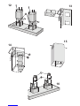
Take the flanges with the metal valves (Fig. 11H) and assemble them onto the opening of the hood for air venting, pressing
slightly. Fit the hood to the telescopic structures by means of 4 +4 screws (provided) – Fig. 12.
Through openings D (Fig. 12) fix the air evacuation pipe to flange H.
Make the electrical connection by means of the power cable. Remove the screw used as catch and slide the lower pipes
downwards, placing them gently on the apparatus. Installation is now complete and the anti-grease filters can be
reassembled.
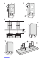
Filtering version: Fix the telescopic structures to the brackets by means of 4+4 screws (provided), running the electric
power cable through the special hole in the bracket (Fig. 6). Adjust the height of the telescopic structures by means of
the 4+4 retaining screws C (Fig. 7), taking into account that the height of the hood is 80 mm and that the distance between
the hood and the hob must be at least 650 mm (Fig. 8). Insert the air baffles (F) in the structure (Fig.13). Through the
openings E (Fig.14), fit the flanges (G) to the baffles (F) locking them with a turning movement. Fix a flexible pipe to the
flanges (G) for air evacuation (Fig. 14). Take the upper pipes (with the round slots) and fit them on the telescopic structure
with the slots facing upwards; fit the pipes to the bracket with 2+2 screws (Fig. 15). Take the lower pipes and fit them
in the same manner as before; slide them to the top and stop them in that position using a screw inserted in the hole of
the upper pipe as a catch (Fig. 10).
Take the flanges (Fig. 16H) with the metal valves and assemble them onto the air venting opening of the hood, pressing
slightly.
Fit the hood to the telescopic structures by means of 4+4 screws (provided) – Fig. 17.
Fix the air evacuation pipes onto the reductions (L).
Make the electrical connection by means of the power cable. Remove the screw used as catch and slide the lower pipes
downwards, placing them gently on the apparatus. Install the charcoal filters clipping the 2 filters clips into place (Fig.18)
and turn the filters upwards. Installation is now complete and the anti-grease filters can be reassembled.
OPERATION
Controls (Fig. 19):
AUTOMATIC OPERATION WITH SENSOR:
Key A: switches the lights on/off. Key B: enables/disables “Automatic” function. When this function is selected,
an “A” appears on the display C, and the speed of the motor increases or decreases depending on the smoke,
odours and gas present in the kitchen. Display C: - indicates the automatic operation of the sensor (the letter
“A” appears);- indicates the motor speed selected automatically by the sensor; indicates the FILTER ALARM
whenever the central segment is illuminated or flashing. Key D: decreases motor speed / Reset; decreases
motor speed to zero (stopping); in any case however, after approximately 1 minute, the hood resumes automatic
operation at the speed set by the sensor. Whenever the key is pressed during the display of FILTER ALARM,
a RESET occurs, and the counting of the hours resumes again. Key E: increases motor speed; in any case
however, after approximately 1 minute, the hood resumes automatic operation at the speed set by the sensor.
Modification of sensor sensitivity: sensor sensitivity can be modified by operating as follows:
- stop the hood by pressing key B. – Simultaneously press keys D and E (the sensor’s sensitivity index will
appear on the display) - Pressing keys D or E, the sensor’s sensitivity will either increase or decrease (1
: minimum sensitivity / 9: maximum sensitivity). – whenever the power supply is interrupted, the sensor will
resume operation with a sensitivity index of 5.
Warning: in order to avoid damaging the sensor, never use silicone products near the hood!
OPERATION AS TRADITIONAL HOOD:
Key A: switches the lights on/off. Display C: - indicates the motor speed selected (from 1 to 4); - indicates
the operation of the Timer when the number is flashing; - indicates filter alarms whenever the central segment
is illuminated or flashing. Key D: decreases motor speed / Stop / Reset; decreases motor speed to zero

(stopping). Whenever the key is pressing during filter alarm display, a RESET occurs, and the counting of the
hours resumes again. Key E: enables the motor / increases motor speed /TIMER. Pressing this key starts
the motor (at the latest speed set); pressing the key again increases motor speed, while keeping the key pressed
down for a few seconds enables the TIMER, and 5 minutes later the motor will stop (while the number of speed
setting selected will simultaneously begin flashing on the display); the Timer will remain enabled if motor speed
is changed. In order to disable the Timer, press the key again.
Grease Filters: special care must be given to the grease filters, which require regular cleaning. The hood indicates
the moment when the grease filters must be cleaned (after approx. 30 hours of operation) by showing the “Ffilter Alarm”
message. Clean these filters as required by use every two months on the average. To remove the filters: press inward
on the clamps at the handles and pull the filter downward (Fig. 3). Wash out the filter using a neutral soap.
Charcoal filters: whenever the unit is supplied with charcoal filters, these filters must be regularly replaced. The
hood indicates the moment when the charcoal filters must be replaced (after approx. 120 hours of operation) by showing
the “Filters Alarm” message. Replace these charcoal filters as required by use every 6 months on the average. Replacing
the charcoal filters: to remove them press inward on the clamp (Fig. 18) and rotate the filter downward until the 2 tabs
can be removed from the housing.
Lighting: Fig. 20: to remove the halogen lamps, turn the locknut counter-clockwise. Replace with the same type of
lamp.
This appliance is marked according to the European directive 2002/96/EC on Waste Electrical and Electronic
Equipment (WEEE). By ensuring this product is disposed of correctly, you will help prevent potential negative
consequences for the environment and human health, which could otherwise be caused by inappropriate waste
handling of this product. The symbol on the product indicates that this product may not be treated as household
waste. Instead it shall be handed over to the applicable collection point for the recycling of electrical and
electronic equipment. Disposal must be carried out in accordance with local environmental regulations for waste
disposal. For more detailed information about treatment, recovery and recycling of this product, please contact
your local city office, your household waste disposal service or the shop where you purchased the product.
FRANCAIS
ATTENTION
La distance minimum entre la surface de support des casseroles sur le plan de cuisson et la partie inférieure de la
hotte doit être de 65 cm. Si les consignes, pour l’installation du plan de cuisson, indiquent une plus grande distance,
il faut en tenir compte.
L'air aspiré ne doit pas être canalisé dans un conduit qui est utilisé pour évacuer les fumées produites par des appareils
alimentés par des sources d'énergies autres que l'énergie électrique (installations de chauffage central, radiateurs,
chauffe-eau, etc.).
Pour évacuer l'air qui doit être éliminé respectez les prescriptions des autorités compétentes. De plus l'air qui doit
être évacué ne doit pas être déchargé dans une cavité du mur, à moins que cette cavité soit prévue pour ce but.
Prévoyez une aération de la pièce adéquate quand une hotte et des appareils alimentés par une énergie autre que
l'énergie électrique (poêle à gaz, à huile, à charbon etc.) sont utilisés en même temps. En effet, en évacuant l'air,
la hotte pourrait créer une dépression dans la pièce. La pression négative de la pièce ne doit pas dépasser 0,04mbar,
évitant ainsi que la source de chaleur provoque un appel des gaz qui doivent être évacués. Il est donc nécessaire
d'équiper la pièce de prises d'air alimentant un flux d'air frais constant.
Contrôler la plaque des caractéristiques techniques se trouvant à l’intérieur de l’appareil; si le symbole ( )
figure sur la plaque suivre les instructions suivantes: cet appareil est construit pour appartenir à la classe
d’isolation II ; il ne doit donc pas être relié à la terre.
Contrôler la plaque des caractéristiques techniques se trouvant à l’intérieur de l’appareil; si le symbole ( )
NE figure pas sur la plaque suivre les instructions suivantes: ATTENTION: cet appareil doit être relié à la terre.
Lors du raccordement électrique s’assurer que la prise de courant est équipée d’une connexion de mise à la terre.
Lors du raccordement électrique assurez-vous que les valeurs de tension correspondent à celles qui sont indiquées
sur la plaque des caractéristiques de l’appareil, qui se trouve à l'intérieur de celui-ci. Si votre appareil, n'a pas de
câble flexible qui ne peut pas être séparé ni de prise, ou bien d'autre dispositif qui garantisse le débranchement de
tous les pôles du réseau, avec une distance d'ouverture entre les contacts d'au moins 3 mm, ces dispositifs de
séparation du réseau doivent alors être prévus dans l'installation fixe. Si votre appareil est muni d’un câble
d’alimentation, positionner l’appareil de manière à ce que la fiche soit accessible.
Avant de procéder à une opération d’entretien ou de nettoyage quelconque, débranchez l’appareil.
UTILISATION
Evitez d'utiliser des matériaux qui provoquent des flammes à proximité de l'appareil.


-
 1
1
-
 2
2
-
 3
3
-
 4
4
-
 5
5
-
 6
6
-
 7
7
-
 8
8
-
 9
9


Küppersbusch IKD18560.0 Instructions For Use And Installation Instructions
- Catégorie
- Hottes
- Taper
- Instructions For Use And Installation Instructions
dans d''autres langues
- English: Küppersbusch IKD18560.0
