Daikin FVXS09NVJU Guide d'installation
- Catégorie
- Climatiseurs split-system
- Taper
- Guide d'installation
Ce manuel convient également à


1
■English
Safety Considerations
• ReadtheseSafety Considerationscarefullytoensure
correctinstallation.
• ThismanualclassiestheprecautionsintoDANGER,
WARNINGandCAUTION.
Besuretofollowalltheprecautionsbelow:theyareall
importantforensuringsafety.
DANGER ����������� Indicatesanimminentlyhazardous
situationwhich,ifnotavoided,will
resultindeathorseriousinjury.
WARNING ��������� FailuretofollowanyofWARNING
islikelytoresultinsuchgrave
consequencesasdeathorserious
injury.
CAUTION ���������� FailuretofollowanyofCAUTION
mayinsomecasesresultingrave
consequences.
• Aftercompletinginstallation,testtheunittocheckfor
installationerrors.Givetheuseradequateinstructions
concerningtheuseandcleaningoftheunitaccordingtothe
OperationManual.
DANGER
• Refrigerantgasisheavierthanairandreplacesoxygen.
Amassiveleakcouldleadtooxygendepletion,especially
inbasements,andanasphyxiationhazardcouldoccur
leadingtoseriousinjuryordeath.
• Iftherefrigerantgasleaksduringinstallation,ventilatethe
areaimmediately.
Refrigerantgasmayproduceatoxicgasifitcomes
incontactwithresuchasfromafanheater,stoveor
cookingdevice.
Exposuretothisgascouldcausesevereinjuryordeath.
• Aftercompletingtheinstallationwork,checkthatthe
refrigerantgasdoesnotleak.
Refrigerantgasmayproduceatoxicgasifitcomes
incontactwithresuchasfromafanheater,stoveor
cookingdevice.
Exposuretothisgascouldcausesevereinjuryordeath.
• Donotgroundunitstowaterpipes,telephonewiresor
lightningrodsbecauseincompletegroundingcouldcause
asevereshockhazardresultinginsevereinjuryordeath,
andtogaspipesbecauseagasleakcouldresultinan
explosionwhichcouldleadtosevereinjuryordeath.
• Safelydisposeofthepackingmaterials.
Packingmaterials,suchasnailsandothermetalor
woodenparts,maycausestabsorotherinjuries.
Tearapartandthrowawayplasticpackagingbagssothat
childrenwillnotplaywiththem.
Childrenplayingwithplasticbagsfacethedangerofdeath
bysuffocation.
• Donotinstallunitinanareawhereammablematerials
arepresentduetoriskofexplosionresultinginserious
injuryordeath.
• Donotgroundunitstotelephonewiresorlightningrods
becauselightningstrikescouldcauseasevereshock
hazardresultinginsevereinjuryordeath,andtogas
pipesbecauseagasleakcouldresultinanexplosion
whichcouldleadtosevereinjuryordeath.
Contents
Safety Considerations ������������������������������������ 1
Accessories ����������������������������������������������������� 3
Choosing an Installation Site ������������������������ 3
1. Indoorunit.............................................................3
2. Wirelessremotecontroller....................................3
Indoor Unit Installation Drawings ����������������� 4
Indoor Unit Installation ����������������������������������� 5
1. Refrigerantpiping.................................................5
2. Drillingawallholeandinstallingwallembedded
pipe.......................................................................7
3. Drainpiping...........................................................7
4. Installingindoorunit..............................................8
4-1. Preparation...................................................8
4-2. Installation.....................................................9
5. Flaringthepipeend..............................................1 2
6. Connectingtherefrigerantpipe............................12
6-1. Cautiononpipinghandling...........................13
6-2. Selectionofcopperandheatinsulation
materials.......................................................13
7. Checkingforgasleakage.....................................1 4
8. Attachingtheconnectionpipe..............................1 4
9. Connectingthedrainhose....................................14
10. Wiring...................................................................1 5
11. WhenconnectingtoanHAsystem......................1 6
12. Howtosetthedifferentaddresses.......................1 7
Trial Operation and Testing ���������������������������� 18
1. Trialoperationandtesting.....................................1 8
2. Testitems..............................................................18
01_EN_3P379970-3.indd 1 10/29/2014 11:23:09 AM

2
■English
WARNING
• Installationshallbelefttotheauthorizeddealeroranother
trainedprofessional.
Improperinstallationmaycausewaterleakage,electrical
shock,re,orequipmentdamage.
• Installtheairconditioneraccordingtotheinstructions
giveninthismanual.
Incompleteinstallationmaycausewaterleakage,
electricalshock,reorequipmentdamage.
• Besuretousethesuppliedorexactspeciedinstallation
parts.
Useofotherpartsmaycausetheunittocometofall,
waterleakage,electricalshock,reorequipmentdamage.
• Installtheairconditioneronasolidbasethatisleveland
cansupporttheweightoftheunit.
Aninadequatebaseorincompleteinstallationmaycause
injuryorequipmentdamageintheeventtheunitfallsoff
thebaseorcomesloose.
• Electricalworkshallbecarriedoutinaccordancewith
theinstallationmanualandthenational,stateandlocal
electricalwiringcodes.
Insufcientcapacityorincompleteelectricalworkmay
causeelectricalshock,reorequipmentdamage.
• Besuretouseadedicatedpowercircuit.Neverusea
powersupplysharedbyanotherappliance.
Followallappropriateelectricalcodes.
• Forwiring,useawireorcablelongenoughtocoverthe
entiredistancewithnosplicesifpossible.
Donotuseanextensioncord.Donotputotherloadson
thepowersupply.
Useonlyaseparatededicatedpowercircuit.
(Failuretodosomaycauseabnormalheat,electricshock,
reorequipmentdamage.)
• Usethespeciedtypesofwiresforelectricalconnections
betweentheindoorandoutdoorunits.
Followallstateandlocalelectricalcodes.
Firmlyclamptheinter-unitwiresotheirterminalsreceive
noexternalstresses.
Incompleteconnectionsorclampingmaycauseterminal
overheating,reorequipmentdamage.
• Afterconnectingallwiresbesuretoshapethecablesso
thattheydonotputunduestressontheelectricalcovers,
panelsorterminals.
Installcoversoverthewires.Incompletecoverinstallation
maycauseterminaloverheating,electricalshock,reor
equipmentdamage.
• Wheninstallingorrelocatingthesystem,besuretokeep
therefrigerantcircuitfreefromallsubstancesotherthan
thespeciedrefrigerant(R410A),suchasair.
(Anypresenceofairorotherforeignsubstanceinthe
refrigerantcircuitcausesanabnormalpressurerisewhich
mayresultinrupture,resultingininjury.)
• Duringpumpdown,stopthecompressorbeforeremoving
therefrigerantpiping.
Ifthecompressorisstillrunningandthestopvalveis
openduringpumpdown,airwillbesuckedinwhenthe
refrigerantpipingisremoved,causingabnormallyhigh
pressurewhichcouldleadtoequipmentdamageorand
personalinjury.
• Duringinstallation,attachtherefrigerantpipingsecurely
beforerunningthecompressor.
Iftherefrigerantpipesarenotattachedandthestopvalve
isopenduringinstallation,airwillbesuckedinwhenthe
compressorisrun,causingabnormallyhighpressure
whichcouldleadtoequipmentdamageandpersonal
injury.
• Besuretoinstallagroundfaultcircuitinterrupter.
Failuretoinstallagroundfaultcircuitinterruptermay
resultinelectricallyshocks,orrepersonalinjury.
CAUTION
• Donotinstalltheairconditionerwheregasleakagewould
beexposedtoopenames.
Ifthegasleaksandbuildsuparoundtheunit,itmaycatch
re.
• Establishdrainpipingaccordingtotheinstructionsofthis
manual.
Inadequatepipingmaycausewaterdamage.
• Tightenthearenutaccordingtothespeciedtorque.A
torquewrenchshouldbeused.
Ifthearenutistightenedtoomuch,thearenutmay
crackovertimeandcauserefrigerantleakage.
• Donottouchtheheatexchangerns.
Improperhandlingmayresultininjury.
• Beverycarefulaboutproducttransportation.
SomeproductsusePPbandsforpackaging.Donot
useanyPPbandsforameansoftransportation.Itis
dangerous.
• Electricalworkmustbeperformedinaccordancewiththe
NEC/CECbyauthorizedpersonnelonly.
English
01_EN_3P379970-3.indd 2 10/29/2014 11:23:09 AM

3
■English
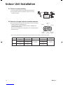
Accessories
A Mountingplate 1 B Titaniumapatitephotocatalytic
air-purifyinglter 2C Drainhose 1
DInsulationtape 2 E Wirelessremotecontroller 1 F Remotecontrollerholder 1
G
Fixingscrewforremote
controllerholder1/8”×13/16”
(M3×20mm)
2HDrybatteryAAA.LR03
(alkaline) 2 J Operationmanual 1
KInstallationmanual 1
Choosing an Installation Site
• Beforechoosingtheinstallationsite,obtainuserapproval.
1� Indoor unit
Theindoorunitshouldbepositionedinaplacewhere:
1)therestrictionsoninstallationrequirementsspeciedin“Indoor Unit Installation Drawings”onpage4aremet,
2)boththeairinletandairoutletareunobstructed,
3)theunitisnotexposedtodirectsunlight,
4)theunitisawayfromthesourceofheatorsteam,
5)thereisnosourceofmachineoilvapour(thismayshortentheindoorunitservicelife),
6)cool/warmairiscirculatedthroughouttheroom,
7)theunitisawayfromelectronicignitiontypeuorescentlamps(inverterorrapidstarttype)astheymayaffecttheremote
controllerrange,
8)theunitisatleast3.3ft(1m)awayfromanytelevisionorradioset(theunitmaycauseinterferencewiththepictureor
sound),
9)nolaundryequipmentisnearby.
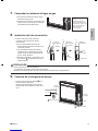
2� Wireless remote controller
Turnonalltheuorescentlampsintheroom,ifany,andndalocationwhereremotecontrollersignalsareproperly
receivedbytheindoorunit(within23ft(7m)).
01_EN_3P379970-3.indd 3 10/29/2014 11:23:09 AM

4
■English
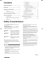
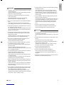
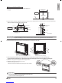
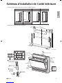
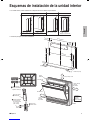
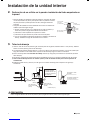
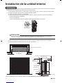
Indoor Unit Installation Drawings
• Theindoorunitmaybemountedinanyofthethreestylesshownhere.
Exposed Half concealed
Floor Installation Wall Installation
Concealed
Grid (field supply)
Mounting
plate
A
Molding
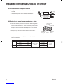
• Locationforsecuringtheinstallationpanel.
unit: inch (mm)
(27-9/16 (700))
2-1/2 (64)
5-1/4
(134)
1 (26)
(23-5/8 (600))
22-5/8 (574)
5-1/2 (140)
9-13/16 (250) 5-7/8 (150)
9-1/16 (230)
25-3/8 (644)
8-1/4
(210)
6-5/16
(160)
1-3/8 (35)
1-3/8 (35)
Titanium apatite photocatalytic
air-purifying filter (2)
B
Front grille
Air filter
Front panel
1-15/16” (50mm)
or more
from walls
2-3/4” (70mm) or more
1-15/16” (50mm)
or more
from walls
Caulk pipe
hole gap
with putty.
Wireless remote
controller
Fixing screw
for remote
controller holder
1/8” × 13/16”
(M3 × 20mm) Remote controller
holder
E
F
G
English
01_EN_3P379970-3.indd 4 10/29/2014 11:23:10 AM

5
■English
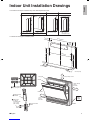
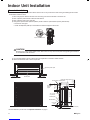
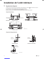
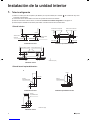
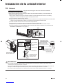
Indoor Unit Installation
1� Refrigerant piping
1)Drillahole(φ2-9/16inch(65mm)indiameter)inthespotindicatedbythe symbolintheillustrationasbelow.
2)Thelocationoftheholeisdifferentdependingonwhichsideofthepipeistakenout.
3)Forpiping,see“6� Connecting the refrigerant pipe”onpage12.
4)Allowspacearoundthepipeforaeasierindoorunitpipeconnection.
<Bottom piping>
1-3/4 (45)
1-3/4
(45)
1-3/4
(45)
1-3/4
(45)
2-3/8 (60)
2-15/16 (75)2-15/16 (75)
2-15/16 (75)2-15/16 (75)
1-3/4 (45)
Left back piping
Left bottom piping Right bottom piping
Wall
Right back piping Left/right piping
Left bottom piping Right bottom piping
2-15/16 (75)
1-15/16
(50)
1-3/8 (35)
Wall
2-15/16 (75)
Exposed installation Half concealed installation
Left bottom piping Right bottom piping
1-3/4 (45)
2-3/8 (60)
2-15/16 (75)
Left/right piping
1-3/4
(45)
1-3/4 (45)
2-15/16 (75)
unit:inch(mm)
Concealed installation
<Left/Right -side piping>
1-3/4 (45)
1-3/4
(45)
1-3/4
(45)
1-3/4
(45)
2-3/8 (60)
2-15/16 (75)2-15/16 (75)
2-15/16 (75)2-15/16 (75)
1-3/4 (45)
Left back piping
Left bottom piping Right bottom piping
Wall
Right back piping Left/right piping
1-3/4(45)
1-15/16 (50)
Wall
Left/right piping
Exposed installation Half concealed installation
Left bottom piping Right bottom piping
1-3/4 (45)
2-3/8 (60)
2-15/16 (75)
Left/right piping
1-3/4
(45)
1-3/4 (45)
2-15/16 (75)
unit:inch(mm)
Concealed installation
01_EN_3P379970-3.indd 5 10/29/2014 11:23:12 AM

6
■English
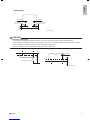
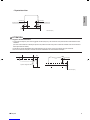
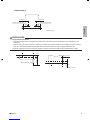
<Back piping>
1-3/4 (45)
1-3/4
(45)
1-3/4
(45)
1-3/4
(45)
2-3/8 (60)
2-15/16 (75)2-15/16 (75)
2-15/16 (75)2-15/16 (75)
1-3/4 (45)
Left back piping
Left bottom piping Right bottom piping
Wall
Right back piping
Left/right piping
unit:inch(mm)
CAUTION
Minimum allowable length
• Thesuggestedshortestpipelengthis8.2ft(2.5m),inordertoavoidnoisefromtheoutdoorunitandvibration.
(Mechanicalnoiseandvibrationmayoccurdependingonhowtheunitisinstalledandtheenvironmentinwhichitisused.)
• Seetheinstallationmanualfortheoutdoorunitforthemaximumpipelength.
• Formulti-connections,seetheinstallationmanualforthemulti-outdoorunit.
13-3/4 (350)
2-15/16 (75)
1-3/4 (45)
Wall
Refrigerant pipe
Floor
unit: inch (mm)
English
01_EN_3P379970-3.indd 6 10/29/2014 11:23:12 AM

7
■English
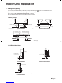
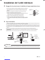
Indoor Unit Installation
2� Drilling a wall hole and installing wall embedded pipe
• Formetalframeormetalboardwalls,besuretouseawallembedded
pipeandwallholecoverinthefeed-throughholetopreventpossibleheat,
electricalshock,orre.
• Besuretocaulkthegapsaroundthepipeswithcaulkingmaterialtoprevent
waterleakage.
1)Drillafeed-throughholewithaφ2-9/16inch(65mm)diameterthroughthe
wallatadownwardangletowardtheoutside.
2)Insertawallembeddedpipeintothehole.
3)Insertawallholecoverintowallpipe.
4)Aftercompletingrefrigerantpiping,wiring,anddrainpiping,caulkthepipe
holegapwithputty.
Inside Outside
Caulking
(field supply)
Wall embedded
pipe
(field supply)
Wall hole cover
(field supply)
φ2-9/16”
(65mm)
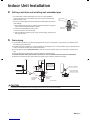
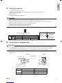
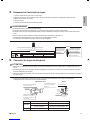
3� Drain piping
1)Usecommercialrigidpolyvinylchloridepipe(generalVP20pipe,outerdiameter1inch(26mm),innerdiameter13/16
inch(20mm))forthedrainpipe.
2)Thedrainhose(outerdiameterφ11/16inch(φ18mm)atconnectingend,8-11/16inch(220mm)long)issuppliedwiththe
indoorunit.Preparethedrainpipepicturebelowposition.
3)
Thedrainpipeshouldbeinclined downwardsothatwaterwillowsmoothlywithoutanyaccumulation.(Shouldnotbe
trap.)
4)Insertthedrainhosetothisdepthsoitwon’tbepulledoutofthedrainpipe.
5)Insulate the indoor drain pipe with 3/8 inch (10mm) or more of insulation material to prevent condensation�
6)Removetheairltersandpoursomewaterintothedrainpantocheckthewaterowssmoothly.
1-15/16
(50)
8-11/16 (220)
5-7/8
(150)
3-15/16
(100)
3-15/16 (100)
Reducer Vinyl chloride
drain pipe
(VP-30)
Vinyl chloride
drain pipe
(VP-20)
Drain hose
C
unit: inch (mm)
Insert drain hose
to this depth so
it won’t be pulled
out of drain pipe. No trap is permitted.
Do not put the end
of the hose in water.
CAUTION
Usepolyvinylchlorideadhesiveagentforgluing.Failuretodosomaycausewaterleakage.
01_EN_3P379970-3.indd 7 10/29/2014 11:23:13 AM

8
■English
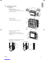
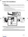
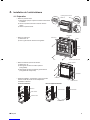
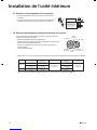
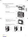
4� Installing indoor unit
4-1� Preparation
• Removethefrontpanel.
1)Slideuntilthe2stoppersclickinside.
2)Openthefrontpanelforwardandremovethestring.
3)Removethefrontpanel.
1)Slide the stoppers.
2)Remove the string.
String
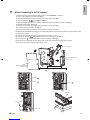
• Removethefrontgrille.
1)Removethe4screws.
2)Pullthefrontgrilleandremovethe3tabs.
Casing
3 tabs
Front grille
4 screws
Remove
front grille
Open the front panel
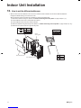
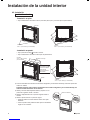
• Removetheupperandthesidecasings.
1)Removethe7screws.
2)Slideandremovetheuppercasing(2tabs).
3)Slideandremovetheleftandrightcasings(2tabson
eachside).
Slit portions
Upper casing
7 screws
Side casing
Side
casing
• Duringinstallation,ifneeded,cuttheslitportionsusing
nippersasshowintheillustrationbelow.
<For moldings> <For side piping>
Side casing
Bottom frame
Slit portions
Side casing
Bottom frame
Slit portions
English
01_EN_3P379970-3.indd 8 10/29/2014 11:23:18 AM

9
■English
Indoor Unit Installation
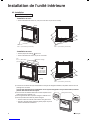
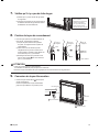
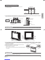
4-2� Installation
Exposed installation
1)Securetheindoorunit
<Floor Installation>
• Securetheindoorunitusing6screws.(2screwsforoorand4screwsforrearwall)
Casing
2 screws
3/16” × 1” (M4 × 25mm) (field supply)
5 screws
3/16” × 1” (M4 × 25mm)
(field supply)
Mounting plate
A
Molding
The mounting
plate should be
installed on a wall
which can support
the weight of the
indoor unit.
A
4 screws
3/16” × 1” (M4 × 25mm) (field supply)
<Wall Installation>
• Securethe Amountingplateusing5screws.
• Securetheindoorunitusing4screwsforrearwall.
Casing
2 screws
3/16” × 1” (M4 × 25mm) (field supply)
5 screws
3/16” × 1” (M4 × 25mm)
(field supply)
Mounting plate
A
Molding
The mounting
plate should be
installed on a wall
which can support
the weight of the
indoor unit.
A
4 screws
3/16” × 1” (M4 × 25mm) (field supply)
2)Oncerefrigerantpipinganddrainpipingconnectionsarecomplete,llinthegapofthethroughholewithputty.
A gap can lead to condensation on the refrigerant pipe, and drain pipe, and the entry of insects into the pipes�
3)Attachandscrewstheeachsidecasingsanduppercasingintheiroriginalpositionusing7screws.
4)Attachthefrontgrillintheiroriginalpositionusing4screws.
5)Attachthefrontpanelintheiroriginalposition.
• Attachthestringtotheright,inner-sideofthefrontgrille.
• Closethefrontpanelandslideuntilthestoppersclickoutside.
Slide the stoppers
01_EN_3P379970-3.indd 9 10/29/2014 11:23:26 AM

10
■English
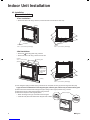
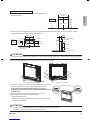
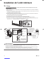
Half concealed installation
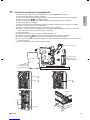
1)Thesizeofawallopeningspaceshownintheillustrationon
theright.
26-3/8 – 27-3/16
(670-690)
23-1/16 – 23-7/16
(585 – 595)
unit: inch (mm)
Open size
Opening space
Floor
2)Therearoftheunitcanbexedwithscrewsatthepointsshownintheillustrationasbelow.Besuretoinstallthesupplemental
plateinaccordancewiththedepthoftheinnerwall.
Fixing point
on the back
Supplemental plate
(field supply)
5-1/2 (140)
9-1/16 (230)
25-3/8 (644)
Screw hole
Screw hole
Opening hole
5-7/8 (150)
9-13/16 (250)
3-3/4 (95)
Supplemental plate
(field supply)
9-13/16 (250)
7-7/8 (200)
unit: inch (mm)
CAUTION
Thesupplementalplateforinstallingthemainunitmustbeused,ortherewillbeagapbetweentheunitandthewall.
3)Securetheindoorunitusing6screws.(2screwsforoorand4screwsforrearwall)
Side casing
Upper casing
Remove 7 screws.
2 screws
(3/16” × 1” (M4 × 25mm))(field supply)4 screws
3/16” × 1” (M4 × 25mm) (field supply)
4)Oncerefrigerantpipinganddrainpipingconnectionsarecomplete,llinthegapofthethroughholewithputty.
A gap can lead to condensation on the refrigerant pipe, and drain pipe, and the entry of insects into the pipes�
5)Attachthefrontgrillintheiroriginalpositionusing4screws.
6)Attachthefrontpanelintheiroriginalposition.
•Attachthestringtothehook.
•Closethefrontpanelandslideuntilthestoppersclickoutside.
Slide the stoppers
CAUTION
• Usedrainpanedgeforhorizontalprojectionoftheindoorunit.
• Installtheindoorunitushagainstwall.
English
01_EN_3P379970-3.indd 10 10/29/2014 11:23:33 AM

11
■English
Indoor Unit Installation
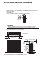
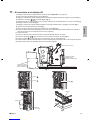
Concealed installation
• Installtheunitaccordingtotheinstructionsbelow.Failuretodosomaycauseleadtobothcoolingandheatingfailureandthe
condensationinsidethehouse.
1)Allowenoughspacebetweenthemainunitandceilingnottoobstructtheowofcool/warmair.
2)Placeapartitionplatebetweenoutletandinletsections.
3)Placeapartitionplateontherightside.
4)Changetheupwardairowdipswitch(SW2-4)toONtolimittheupwardairow.(Factorydefault:OFF)
• Removethefrontgrille.
• Switchthedipswitch(SW2-4)onthePCBintheelectricalequipmentboxtoON.
Upward airflow dipswitch
CAUTION
Besuretoturnontheupwardairowswitch.Failuretodosomaycauseincompletecooling/heatingandformation
ofcondensationinsidethehouse.
5)Useamovablelatticeattheairoutlettoallowtheadjustmentofcool/warmairowdirection.
6)Latticesizeshouldbe70%ormoreofopenrate.
Right side partition plate
Partition plate
1-15/16 (50)
or more
1-15/16 (50)
or more
Partition plate
Movable lattice
9/16 – 13/16
(15 – 20)
16-1/8 (410)
4-3/4
(120)
70% or more
of open rate
1-9/16 (40)
or less
13/16
–
1-3/16 (20-30)
Upper lattice
must not
project
Right side partition plate
Partition plate
Movable lattice
2-3/4 (70)
or more
unit: inch (mm)
• Fortheinstallationprocessreferto“Exposed installation”onpage9.
01_EN_3P379970-3.indd 11 10/29/2014 11:23:35 AM

12
■English
5� Flaring the pipe end
1)Cutthepipeendwithapipecutter.
2)Removeburrswiththecutsurfacefacingdownwardsothatthechipsdonotenterthepipe.
3)Putthearenutonthepipe.
4)Flarethepipe.
5)Checkthatthearingisproperlymade.
WARNING
• Donotusemineraloilonaredpart.
• Preventmineraloilfromgettingintothesystemasthiswouldreducethelifetimeoftheunits.
• Neverusepipingwhichhasbeenusedforpreviousinstallations.Onlyusepartswhicharedeliveredwiththeunit.
• NeverinstalladriertothisR410Aunitinordertoguaranteeitslifetime.
• Thedryingmaterialmaydissolveanddamagethesystem.
• Incompletearingmaycauserefrigerantgasleakage.
Flare’s inner
surface must
be flaw-free.
The pipe end must
be evenly flared in
a perfect circle.
Make sure that the
flare nut is fitted.
Set exactly at the position shown below.
A
Flaring
Die A0-0.020 inch (0-0.5mm)
Clutch-type
Flare tool for R410A
0.039-0.059 inch (1.0-1.5mm)
Clutch-type (Rigid-type)
0.059-0.079 inch (1.5-2.0mm)
Wing-nut type (Imperial-type)
Conventional flare tool
Cut exactly at right angles.
Remove burrs Check
6� Connecting the refrigerant pipe
CAUTION
• Usethearenutxedtothemainunit.(Thisistopreventcrackingofthearenutasaresultofdeteriorationovertime.)
• Topreventgasleakage,applyrefrigerationoilonlytotheinnersurfaceoftheare.(UserefrigerationoilforR410A.)
• Useatorquewrenchwhentighteningthearenutstopreventdamagetothearenutsandgasleakage.
• Alignthecenterofbotharesandtightenthearenuts3or4turnsbyhand.Thentightenthemfullywithaspanneranda
torquewrench.
Torque wrench
Piping union
Flare nut
Do not apply refrigeration
oil to the outer surface.
Flare nut
Apply refrigeration oil to
the inner surface of the
flare.
Do not apply refrigeration oil to
the flare nut to avoid tightening
with excessive torque.
Spanner
Apply oil Tighten
Pipingsize Flarenuttighteningtorque
Gasside 3/8inch(9.5mm) 24.1-29.4ft•Ibf(32.7-39.9N•m)
1/2inch(12.7mm) 36.5-44.5ft•lbf(49.5-60.3N•m)
Liquidside 1/4inch(6.4mm) 10.5-12.7ft•lbf(14.2-17.2N•m)
English
01_EN_3P379970-3.indd 12 10/29/2014 11:23:36 AM

13
■English
Indoor Unit Installation
6-1� Caution on piping handling
1)Protecttheopenendofthepipeagainstdustandmoisture.
2)Allpipebendsshouldbeasgentleaspossible.Useapipe
benderforbending.
Wall
If no flare cap is
available, cover
the flare mouth
with tape to keep
dirt or water out.
Be sure to
place a cap.
Rain
6-2� Selection of copper and heat insulation materials
Whenusingcommercialcopperpipesandttings,observethefollowing:
• Insulationmaterial:Polyethylenefoam
Heattransferrate:0.041to0.052W/mK(0.024to0.030Btu/fth°F
(0.035to0.045kcal/mh°C))
BesuretouseinsulationthatisdesignedforusewithHVACSystems.
• ACRCopperonly.
Liquid pipe
Gas pipe
Gas pipe
insulation
Liquid pipe
insulation
Finishing tape
Inter-unit
wiring
• Besuretoinsulateboththegasandliquidpipingandobservetheinsulationdimensionsasbelow.
Gas side
Piping size
O.D. 3/8 inch
(9.5mm)
O.D. 1/2 inch
(12.7mm)
O.D. 1/4 inch
(6.4mm)
1-3/16 inch (30mm)
or more
1-9/16 inch (40mm)
or more
1-3/16 inch (30mm)
or more
0.031 inch (0.8mm)
(C1220T-O)
I.D. 15/32-19/32 inch
(12-15mm)
I.D. 9/16-5/8 inch
(14-16mm)
I.D. 5/16-13/32 inch
(8-10mm)
13/32 inch
(10mm) Min.
Minimum bend radius Piping thickness Thermal insulation size Thermal insulation
thickness
Liquid side
• Useseparatethermalinsulationpipesforgasandliquidrefrigerantpipes.
01_EN_3P379970-3.indd 13 10/29/2014 11:23:37 AM

14
■English
7� Checking for gas leakage
1)Checkforleakageofgasafterairpurging.
2)Seethesectionsonairpurgesandgasleak
checksintheinstallationmanualforthe
outdoorunit.
Check for leakage here.
•Apply soapy water and
check carefully for leaking
gas.
•Wipe soapy water off after
the check is complete.
8� Attaching the connection pipe
• Attachthepipeaftercheckingforgasleakage,
describedabove.
1)Cuttheinsulatedportionoftheon-sitepiping,
matchingitupwiththeconnectingportion.
2)Securetheslitontherefrigerantpipingside
withthebuttjointontheauxiliarypipingusing
thetape,makingsuretherearenogaps.
3)Wraptheslitandthebuttjointwiththe
Dinsulationtape,makingsurethereareno
gaps.
Refrigerant
pipe
Refrigerant
pipe
Refrigerant
pipe
2)1) 3)
Auxiliary pipe
Slit Slit
Tape
Insulation
tape
D
CAUTION
• Insulatethejointofthepipessecurely.
Incompleteinsulationmayleadtowaterleakage.
• Pushthepipeinsidesoitdoesnotplaceundueforceonthefrontgrille.
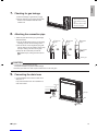
9� Connecting the drain hose
• Insertthe Cdrainhoseintothesocketofthe
drainpan.
Fullyinsertthedrainhoseuntilitadherestoa
sealofthesocket.
Drain pan
Drain pan
Seal
Seal
Drain hose
C
Drain hose
C
English
01_EN_3P379970-3.indd 14 10/29/2014 11:23:40 AM

15
■English
Indoor Unit Installation
10� Wiring
With a Multi indoor unit , install as described in the installation manual supplied with the Multi outdoor unit�
• Livethesensorsecuringplate,removethefrontmetalplatecover,andconnectthebranchwiringtotheterminalblock.
1)Asshownintheillustration,insertthewiresincludingthegroundwireintotheconduitandsecurethemwithlocknut
ontotheconduitmountingplate.
2)Stripwireends(3/4inch(20mm)).
3)Matchwirecolourswithterminalnumbersonindoorandoutdoorunit’sterminalblocksandrmlysecurethewiresin
thecorrespondingterminalswiththescrews.
4)Connectthegroundwirestothecorrespondingterminals.
5)Pullthewireslightlytomakesuretheyaresecurelyconnected.
6)Makesurethatthewiresdonotcomeincontactwiththemetalconduitfortheheatexchanger.
7)Incaseofconnectingtoanadaptersystem.RuntheremotecontrollercableandattachtheS21.(Referto“11� When
connecting to an HA system”onpage16.)
Conduit
mounting
plate
Conduit
Lock nut
Back
1
2
3
1 2 3
L
2
123
L
1
Use AWG 14 wires.
Firmly fix the wires with
the terminal screws.
Outdoor unit
Indoor
unit
Firmly fix the wires with
the terminal screws.
Use AWG16 if the connection wire
length is less than 33ft (10m), or
AWG14 if it is 33ft (10m) or more.
Terminal block
Electrical
component
box
Wire retainer
Use the specified
wire type.
Make sure that the wires
do not come in contact
with the metal conduit
for the heat exchanger.
Shape wires so
that the front metal
plate cover will fit
securely.
Front metal
plate electrical
wiring box cover
Sensor securing plate
WARNING
• Donotusetappedwires,strandedwires,extensioncords,orstarburstconnections,astheymaycauseoverheating,
electricalshock,orre.
• Donotuselocallypurchasedelectricalpartsinsidetheproduct.(Donotbranchthepowerforthedrainpump,etc.,fromthe
terminalblock.)Doingsomaycauseelectricshockorre.
• Donotconnectthepowerwiretotheindoorunit.Doingsomaycauseelectricshockorre.
01_EN_3P379970-3.indd 15 10/29/2014 11:23:42 AM

16■English
11� When connecting to an HA system
1)Removethefrontpanelandthefrontgrille.(Referto“4-1� Preparation”onpage8.)
2)Openupthesensorsecuringplate.(SeeFig� 1)
3)Removethefrontmetalplateelectricalwiringboxcover(4tabs).(SeeFig� 1)
4)Removeconnectors 123.(SeeFig� 2andFig� 3)
5)Afterremovingthegroundwires(2screws),removetheelectricalwiringbox(1screw).(SeeFig� 4)
6)Removethethermistor.(SeeFig� 5)
7)Removethesidemetalplateelectricalwiringboxcover(7tabs).(SeeFig� 1)
8)Cutoffthepinsusinganipper.(SeeFig� 1)
9)WireandconnecttheHAconnectioncordtotheS21connector.(SeeFig� 1)
10)
InstallthesidemetalplateelectricalwiringboxcoverwhilebeingcarefulnottopinchtheHAconnectioncordorgroundwires(7tabs).
11)Attachthethermistor.
12)Installthegroundwires(2screws)andtheelectricalwiringbox(1screw).
13)Installtheconnectors 12andguidethecordasshowninthegure.(SeeFig� 2)
14)Installconnector 3andguidethecordasshowninthegure.(SeeFig� 3)
15)Attachthefrontmetalplateelectricalwiringboxcover(4tabs),andclosethesensorsecuringplate.
16)Attachthefrontpanelandthefrontgrilleastheywere.
S21
Sensor securing plate
Front metal plate electrical
wiring box cover
Side metal plate electrical
wiring box cover Cut off the pins using a nipper.
Be careful not to pinch the HA connection cord or ground wire.
Fig� 1
Connector 1
Connector 2Connector 3
Fig� 2 Fig� 3
Screws
Ground wires
Thermistor
Fig� 4 Fig� 5
English
01_EN_3P379970-3.indd 16 10/29/2014 11:23:48 AM

17 ■English
Indoor Unit Installation
12� How to set the different addresses
• When2indoorunitsareinstalledinoneroom,the2wirelessremotecontrollerscanbesetfordifferentaddresses.
Changetheaddresssettingofoneofthetwounits.
Whencuttingthejumperbecarefulnottodamageanyofthesurroundingparts.
1)Removetheelectricalwiringbox.(Referto“11� When connecting to an HA system”onpage16steps1)-7).)
2)Cuttheaddressjumper(JA)ontheprintedcircuitboard.
3)Cuttheaddressjumper(J4)intheremotecontroller.
4)
Attachtheelectricalwiringboxastheywere.(Referto“11� When connecting to an HA system”onpage16steps10)-15).)
5)Attachthefrontpanelandthefrontgrilleastheywere.
Jumper
(J8) (J4)
J4
ADRESS
EXIST
1
CUT 2
JA
ADRESS
EXIST
1
CUT 2
JA
Front metal plate cover
Side metal plate cover
Sensor
securing plate
01_EN_3P379970-3.indd 17 10/29/2014 11:23:49 AM

18■English
Trial Operation and Testing
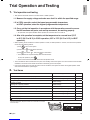
1� Trial operation and testing
• TrialoperationshouldbecarriedoutineitherCOOLorHEAToperation.
1-1� Measure the supply voltage and make sure that it is within the specied range.
1-2� In COOL operation, select the lowest programmable temperature;
in HEAT operation, select the highest programmable temperature�
1-3� Carry out the trial operation in accordance with the operation manual to ensure
that all functions and parts, such as ap movement, are working properly.
• Forprotection,thesystemdisablesrestartoperationfor3minutesafteritisturnedoff.
1-4� After trial operation is complete, set the temperature to a normal level (78°F
to 82°F (26°C to 28°C) in COOL operation, 68°F to 75°F (20°C to 24°C) in HEAT
operation)�
• WhenoperatingtheairconditionerinCOOLoperationinwinter,orHEAToperationinsummer,setittothetrialoperation
modeusingthefollowingmethod.
1)Press toturnonthesystem.
2)Pressbothof and atthesametime.
3)Press ,thenselect“ ”,andpress forconrmation.
• Trialoperationwillstopautomaticallyafterabout30minutes.
Tostoptheoperation,press .
• Someofthefunctionscannotbeusedinthetrialoperationmode.
• Theairconditionerdrawsasmallamountofpowerinitsstandbymode.Ifthesystemisnottobeusedforsometimeafter
installation,shutoffthecircuitbreakertoeliminateunnecessarypowerconsumption.
• Ifthecircuitbreakertripstoshutoffthepowertotheairconditioner,thesystemwillrestoretheoriginaloperationmode
whenthecircuitbreakerisopenedagain.
2� Test items
TestItems Symptom Check
Indoorandoutdoorunitsareinstalledproperlyonsolidbases. Fall,vibration,noise
Norefrigerantgasleaks. Incompletecooling/heatingfunction
Refrigerantgasandliquidpipesandindoordrainhoseextensionare
thermallyinsulated. Waterleakage
Draininglineisproperlyinstalled. Waterleakage
Systemisproperlygrounded. Electricalleakage
Thespeciedwiresareusedforinter-unitwiringconnections. Nooperationorburndamage
Indoororoutdoorunit’sairinletorairoutletareunobstructed. Incompletecooling/heatingfunction
Stopvalvesareopened. Incompletecooling/heatingfunction
Indoorunitproperlyreceivesremotecontrolcommands. Nooperation
willbedisplayedwhentheMODEbuttonispressed.* Noheating
*Checkthatthejumper(J8)hasnotbeencut.Ifithasbeencut,contact
theserviceshop. Jumper (J8)
English
01_EN_3P379970-3.indd 18 10/29/2014 11:23:52 AM

1
■Français
Considérations sur la sécurité
• LisezattentivementcesConsidérations sur la sécurité
pourassureruneinstallationcorrecte.
• Cemanuelclasselesprécautionsdelamanièresuivante,
DANGER,AVERTISSEMENTetATTENTION.
Assurez-vousdesuivretouteslesprécautionsci-dessous:
ellessonttoutesessentiellespourassurerlasécurité.
DANGER ����������� Indiqueunesituationextrêmement
dangereusequi,siellen'estpas
évitée,entraîneralamortoudes
blessuresgraves.
AVERTISSEMENT
��� Lenon-respectdel'unedes
précautionsAVERTISSEMENT
estsusceptibled'entraînerdes
conséquencesaussidramatiques
quelamortoudegravesblessures.
ATTENTION ������ Lenon-respectdel'unedes
précautionsATTENTIONpeut,dans
certainscas,entraînerdegraves
conséquences.
•
Aprèsavoirterminél'installation,testezl'unitépourvérier
qu'iln'yapasd'erreurdansl'installation.Donnezàl'utilisateur
lesinstructionsadéquatesconcernantl'utilisationetle
nettoyagedel'unitéconformémentaumanueld'utilisation.
DANGER
• Legazréfrigérantestpluslourdquel'airetremplace
l'oxygène.Unefuiteimportantepeutconduireàun
appauvrissementenoxygène,enparticulierensous-sol,
etunrisqued'asphyxiepeutsurveniretentraînerdes
blessuresgravesoulamort.
•
Sivousconstatezdesfuitesdegazréfrigérantpendant
l'installation,aérezimmédiatementlazone.
Legazréfrigérantpeutproduireungaztoxiques'ilentreen
contactavecuneammecommeàpartird'unventilateur
dechauffage,unecuisinièreouunappareildecuisson.
L'expositionàcegazpeutprovoquerdesblessuresgraves
oulamort.
•
Aprèsl'achèvementdestravauxd'installation,vériezque
legazréfrigérantnefuitpas.
Legazréfrigérantpeutproduireungaztoxiques'ilentreen
contactavecuneammecommeàpartird'unventilateur
dechauffage,unecuisinièreouunappareildecuisson.
L'expositionàcegazpeutprovoquerdesblessuresgraves
oulamort.
• Nereliezpaslesunitésàdesconduitesd'eau,àdes
câblestéléphoniquesouàdesparatonnerres,carune
miseàlaterreincomplètepeutprovoquerunrisque
d'électrocutionimportantpouvantentraînerdesblessures
gravesoulamort;nelesreliezpasnonplusàdestuyaux
degazcarunefuitedegazpeutprovoqueruneexplosion
etentraînerdesblessuresgravesoulamort.
• Mettezprudemmentaurebutlesmatériauxd'emballage.
Lesmatériauxd'emballage,telsquelesclousetautres
piècesenmétalouenbois,peuventcauserdescoupures
oud'autresblessures.
Déchirezetjetezlessacsd'emballageenplastiquepour
quelesenfantsnepuissentpasjoueravec.
Lesenfantsquijouentavecdessacsenplastiquerisquent
demourirparsuffocation.
• N'installezpasuneunitédansunendroitoùdes
matériauxinammablessontprésentsenraisondurisque
d'explosionpouvantentraînerdesblessuresgravesoula
mort.
•
Nereliezpaslesunitésàdescâblestéléphoniquesouà
desparatonnerrescardeséclairspeuventprovoquerun
risqued'électrocutionimportantpouvantentraînerdes
blessuresgravesoulamort;nelesreliezpasnonplusà
destuyauxdegazcarunefuitedegazpeutprovoquerune
explosionetentraînerdesblessuresgravesoulamort.
Sommaire
Considérations sur la sécurité ���������������������� 1
Accessoires ����������������������������������������������������� 3
Choix du site de l’installation ������������������������ 3
1. Unitéintérieure.....................................................3
2. Télécommandesansl.........................................3
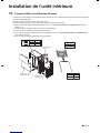
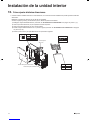
Schémas d'installation de l’unité intérieure ���
4
Installation de l'unité intérieure ��������������������� 5
1. Tuyauteriederéfrigérant.......................................5
2. Perçaged'untroudanslemuretinstallationdu
tuyauencastrédanslemur..................................7
3. Tuyaud’évacuation...............................................7
4. Installationdel’unitéintérieure.............................8
4-1. Préparation...................................................8
4-2. Installation.....................................................9
5. Évasementdel'extrémitédutuyau.......................12
6. Connexiondutuyauderéfrigérant.......................12
6-1.
Attentionàlamanipulationdelatuyauterie
...13
6-2. Sélectiondesmatériauxd'isolationthermique
etencuivre...................................................13
7. Vériezqu'iln'yapasdefuitedegaz...................14
8. Fixationdutuyauderaccordement......................14
9. Connexiondutuyaud’évacuation.........................14
10. Câblage................................................................15
11. LorsdelaconnexionàunsystèmeHA................1 6
12. Commentdénirlesdifférentesadresses............17
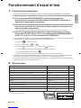
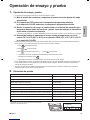
Fonctionnement d’essai et test ��������������������� 18
1. Fonctionnementd’essaiettest.............................18
2. Élémentstestés....................................................18
02_FR_3P379970-3.indd 1 10/29/2014 11:52:26 AM
La page charge ...
La page charge ...
La page charge ...
La page charge ...
La page charge ...
La page charge ...
La page charge ...
La page charge ...
La page charge ...
La page charge ...
La page charge ...
La page charge ...
La page charge ...
La page charge ...
La page charge ...
La page charge ...
La page charge ...
La page charge ...
La page charge ...
La page charge ...
La page charge ...
La page charge ...
La page charge ...
La page charge ...
La page charge ...
La page charge ...
La page charge ...
La page charge ...
La page charge ...
La page charge ...
La page charge ...
La page charge ...
La page charge ...
La page charge ...
La page charge ...
La page charge ...
-
 1
1
-
 2
2
-
 3
3
-
 4
4
-
 5
5
-
 6
6
-
 7
7
-
 8
8
-
 9
9
-
 10
10
-
 11
11
-
 12
12
-
 13
13
-
 14
14
-
 15
15
-
 16
16
-
 17
17
-
 18
18
-
 19
19
-
 20
20
-
 21
21
-
 22
22
-
 23
23
-
 24
24
-
 25
25
-
 26
26
-
 27
27
-
 28
28
-
 29
29
-
 30
30
-
 31
31
-
 32
32
-
 33
33
-
 34
34
-
 35
35
-
 36
36
-
 37
37
-
 38
38
-
 39
39
-
 40
40
-
 41
41
-
 42
42
-
 43
43
-
 44
44
-
 45
45
-
 46
46
-
 47
47
-
 48
48
-
 49
49
-
 50
50
-
 51
51
-
 52
52
-
 53
53
-
 54
54
-
 55
55
-
 56
56


Daikin FVXS09NVJU Guide d'installation
- Catégorie
- Climatiseurs split-system
- Taper
- Guide d'installation
- Ce manuel convient également à
dans d''autres langues
- English: Daikin FVXS09NVJU Installation guide
- español: Daikin FVXS09NVJU Guía de instalación
Documents connexes
Autres documents
-
Mitsubishi Electric PEAD-A36AA Guide d'installation
-
Haier HSU12VHJDBW Guide d'installation
-
-
Friedrich MR36TQY3JM Mode d'emploi
-
LG LMU18CHV.AWGBEUS Guide d'installation
-
-
BUT Table basse SQUARE Imitation chêne et noir Mode d'emploi