Chief FMSCAO Guide d'installation
- Catégorie
- Supports de projecteur
- Taper
- Guide d'installation

INSTALLATION INSTRUCTIONS
Fusion Ceiling Mount Offset
Spanish Product Description
German Product Description
Portuguese Product Description
Italian Product Description
Dutch Product Description
French Product Description
FMSCAO

FMSCAO Installation Instructions
2
DISCLAIMER
Milestone AV Technologies and its affiliated corporations and
subsidiaries (collectively “Milestone”), intend to make this
manual accurate and complete. However, Milestone makes no
claim that the information contained herein covers all details,
conditions or variations, nor does it provide for every possible
contingency in connection with the installation or use of this
product. The information contained in this document is subject
to change without notice or obligation of any kind. Milestone
makes no representation of warranty, expressed or implied,
regarding the information contained herein. Milestone assumes
no responsibility for accuracy, completeness or sufficiency of
the information contained in this document.
Chief® is a registered trademark of Milestone AV Technologies.
All rights reserved.
DEFINITIONS
MOUNTING SYSTEM: A MOUNTING SYSTEM is the
primary Chief product to which an accessory and/or component
is attached.
ACCESSORY: AN ACCESSORY is the secondary Chief
product which is attached to a primary Chief product, and may
have a component attached or setting on it.
COMPONENT: A COMPONENT is an audiovisual item
designed to be attached or resting on an accessory or mounting
system such as a video camera, CPU, screen, display,
projector, etc.
WARNING: A WARNING alerts you to the possibility of
serious injury or death if you do not follow the instructions.
CAUTION: A CAUTION alerts you to the possibility of
damage or destruction of equipment if you do not follow the
corresponding instructions.
IMPORTANT SAFETY INSTRUCTIONS
WARNING: Failure to read, thoroughly understand, and
follow all instructions can result in serious personal injury,
damage to equipment, or voiding of factory warranty! It is the
installer’s responsibility to make sure all mounting systems /
accessories are properly assembled and installed using the
instructions provided.
WARNING: Exceeding the weight capacity can result in
serious personal injury or damage to equipment! It is the
installer’s responsibility to make sure the combined weight of
all components attached to mounting system does not
exceed 500 lbs (226.8 kg).
IMPORTANT ! : These installation instructions must be
used in conjunction with the Fusion Modular Systems
installation instructions.
--SAVE THESE INSTRUCTIONS--

Installation Instructions FMSCAO
3
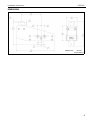
DIMENSIONS
DIMENSIONS: INCHES
[MILLIMETERS]

FMSCAO Installation Instructions
4
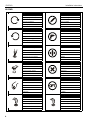
LEGEND
Tighten Fastener
Apretar elemento de fijación
Befestigungsteil festziehen
Apertar fixador
Serrare il fissaggio
Bevestiging vastdraaien
Serrez les fixations
Loosen Fastener
Aflojar elemento de fijación
Befestigungsteil lösen
Desapertar fixador
Allentare il fissaggio
Bevestiging losdraaien
Desserrez les fixations
Phillips Screwdriver
Destornillador Phillips
Kreuzschlitzschraubendreher
Chave de fendas Phillips
Cacciavite a stella
Kruiskopschroevendraaier
Tournevis à pointe cruciforme
Open-Ended Wrench
Llave de boca
Gabelschlüssel
Chave de bocas
Chiave a punte aperte
Steeksleutel
Clé à fourche
By Hand
A mano
Von Hand
Com a mão
A mano
Met de hand
À la main
Hex-Head Wrench
Llave de cabeza hexagonal
Sechskantschlüssel
Chave de cabeça sextavada
Chiave esagonale
Zeskantsleutel
Clé à tête hexagonale
Pencil Mark
Marcar con lápiz
Stiftmarkierung
Marcar com lápis
Segno a matita
Potloodmerkteken
Marquage au crayon
Drill Hole
Perforar
Bohrloch
Fazer furo
Praticare un foro
Gat boren
Percez un trou
Adjust
Ajustar
Einstellen
Ajustar
Regolare
Afstellen
Ajuster
Remove
Quitar
Entfernen
Remover
Rimuovere
Verwijderen
Retirez
Optional
Opcional
Optional
Opcional
Opzionale
Optie
En option
Security Wrench
Llave de seguridad
Sicherheitsschlüssel
Chave de segurança
Chiave di sicurezza
Veiligheidssleutel
Clé de sécurité

Installation Instructions FMSCAO
5
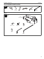
TOOLS REQUIRED FOR INSTALLATION
PARTS
1/2"
1/2"
1/2"
nut driver
5/32"
(included) 7/32"
(included)
A (1)
[Array offset]
B (4)
5/16-18 x 1/2" C (8)
5/16-18 x 1" D (8)
5/16"
E (8)
5/16"
F (1)
5/32" G (1)
7/32"

FMSCAO Installation Instructions
6
INSTALLATION
IMPORTANT ! : Be sure to also reference ceiling system
attachment guidelines in the Fusion Modular Systems
installation instructions.
NOTE: The following procedure assumes that Chief ceiling
plates (not included) and extension columns (not
included) have been properly installed following
instructions provided with ceiling plates and extension
columns.
•The ceiling plates and columns should be installed
approximately spaced at center of outside
screens.
IMPORTANT ! : The weight of the system should be
evenly distributed across ceiling plates.
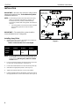
Installing Array Offset
1. Measure depth of screens to be installed and compare to
offset position information. (Table 1)
Table 1: Offset Position for Screen Depth
NOTE: The array offset (A) ships in the centered position. If the
screen depth is 2.5" to 4.5" leave the array offset as is,
and proceed to Attaching Array Offset to Installed
Column section.
2. Loosen and remove fastener and washer from center hole
on each side of array offset (A). (See Figure 1)
3. Loosen two outside fasteners on each side of array offset (A).
4. Slide offset to appropriate position. (See Figure 1)
5. Tighten two outside fasteners on each side of offset.
6. Install and tighten fastener with washer (removed in Step 2)
into appropriate hole on each side of offset. (See Figure 1)
Figure 1
ARRAY
OFFSET Forward
Position Center
Position Rear
Position
Screen
Depth < 2.5" depth 2.5" to 4.5"
depth > 4.5" depth
6
2
(A)
44
Towards front
of menu board
5
3
Forward Rear position
Centered
position
position
center hole

Installation Instructions FMSCAO
7
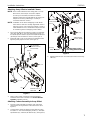
Attaching Array Offset to Installed Column
NOTE: If the column attached to the ceiling plate is a 1-1/2"
NPT column, the Chief pin connection adapter
accessory (not included) must first be installed
following instructions included with the accessory. No
adapter is necessary if attaching to a Chief pin
connection extension column.
NOTE: Installation of hex head self-tapping screws will be
easier when screws are carefully aligned with holes in
extension column, and a drill and nut driver is used. If
a drill will NOT be used, a small amount of pressure will
be needed to get the self-tapping screws started.
1. Secure array offset (A) to extension column (not included)
using four 5/16-18 x 1" hex head self-tapping screws (C),
four 5/16" split lock washers (D) and four 5/16" flat washers
(E) through holes in extension column. (See Figure 2)
2. Install two 5/16" x 1/2" set screws (B) into threaded holes,
tightening firmly against column. (See Figure 2)
Figure 2
3. Attach ceiling heads to extension columns following
installation instructions included in the Fusion Modular
Systems installation manual.
Attaching Column Assembly to Array Offset
1. Arrange column assembly so that the open side of the
ceiling head is facing the back of the menu board. (See
Figure 3)
2.
Loosely fasten column assembly to array offset (A) using
four 5/16" x 1" hex head self-tapping screws (C), four 5/16"
split washers (D), and four 5/16" washers (E). (See Figure 3)
Figure 3
3. Add two 5/16-18 x 1/2" set screws (B) to lower end of array
offset (A).
2
1
Pin connection
(A)
(B) x 2
(C) x 4
(D) x 4
(E) x 4
Towards rear of
video wall
(not included)
extension column
Towards front
of menu board
Towards back
of menu board
2
(C) x 4
(E) x 4
(D) x 4
(A)
(Installed upper column
and ceiling plate not shown)
3
(B) x 2
(Ceiling
head)

FMSCAO Installation Instructions
USA/International A 6436 City West Parkway, Eden Prairie, MN 55344
P800.582.6480 / 952.225.6000
F877.894.6918 / 952.894.6918
Europe A Franklinstraat 14, 6003 DK Weert, Netherlands
P+31 (0) 495 580 852
F+31 (0) 495 580 845
Asia Pacific A Office No. 918 on 9/F, Shatin Galleria
18-24 Shan Mei Street
Fotan, Shatin, Hong Kong
P852 2145 4099
F852 2145 4477
Chief, a products division of
Milestone AV Technologies
8800-003028 Rev00
2018 Milestone AV Technologies
www.milestone.com
02/18
-
 1
1
-
 2
2
-
 3
3
-
 4
4
-
 5
5
-
 6
6
-
 7
7
-
 8
8


Chief FMSCAO Guide d'installation
- Catégorie
- Supports de projecteur
- Taper
- Guide d'installation
dans d''autres langues
- English: Chief FMSCAO Installation guide
Documents connexes
-
Chief KTA1001B Guide d'installation
-
-
Chief FCA540 Guide d'installation
-
Chief FCA4U Guide d'installation
-
Chief FCA3U Guide d'installation
-
-
-
Chief LCM1U Guide d'installation
-
Chief CPA330 Guide d'installation
-
Chief Manufacturing CMA105-OB Manuel utilisateur