La page est en cours de chargement...

Integral
Horticulture LED Lighting System
Installation Guide
HORT166 | DOC-2001858
BEFORE YOU BEGIN / AVANT DE COMMENCER
Read these instructions completely and carefully. Lisez attentivement ces instructions dans leur intégralité.
0°C
40°C
Suitable for operation in an ambient temperature between
32°F (0°C) and 104°F (40°C).
A mechanical ventilation or cooling system is required to
maintain the temperature within the growing space below
104°F (40°C) when the light module is in operation.
Opération compatible avec un environnement à temperature
ambiante controlée entre 32°F (0°C) et 104°F (40°C).
L’utilisation d’un système de contrôle de la température sera
nécessaire pour garder la serre sous les 104°F (40°C) lorsque le
luminaire est en function.
Visit www.LED.com
Call us today! 1-888-694-3533
Email us:
horticulture.info@gecurrent.com
WARNING / AVERTISSEMENT
RISK OF ELECTRIC SHOCK
• Turn power o before installation, inspection, cleaning or removal.
• Do NOT make or break connections under load.
• Follow appropriate lock out/tag out safety procedure.
• Follow all National Electric Codes (NEC) and local codes.
• This product must be installed in accordance with the applicable
installation code by a person familiar with the construction and oper-
ation of the product and the hazards involved.
• The installation and associated structures are subject to approval by
the authority having jurisdiction.
• Use only with components identied in this document.
• Suitable for dry, damp, and wet locations; Do not immerse any
component.
• For commercial or industrial use only.
RISK OF FIRE
• The luminaire shall be installed with a minimum of 5 inches between
the light module and any highly reective surface.
• All cables including connectors shall not be concealed or extended
through a wall, oor, ceiling, or other parts of the building structure;
located above a suspended ceiling or dropped ceiling; permanently
axed to the building structure.
• Cables shall be routed so that they are not subject to strain and are
protected from physical damage; visible over their entire length; and
used within their rated ampacity as determined for the maximum
temperature of the installed environment specied in the instructions.
• Before applying power, ensure that any open female connectors in the
installation are sealed with an end cap.
• For safe operation, and to maximize the longevity of the luminaire;
ensure that the luminaire is clean and free of dirt, dust, oil, or any other
debris. Do not apply any kind of lm on the lens or otherwise cover
the luminaire in any way.
RISQUE DE CHOC ELECTRIQUE
• Coupez l’alimentation avant l’inspection, l’installation ou le déplacement.
• Ne PAS brancher ou débrancher si le système est sous tension.
• Suivez la procédure de sécurité appropriée de verrouillage/étiquetage.
• Suivre tous les codes électriques locaux applicables.
• Ce produit doit être installé selon le code d’installation pertinent, par
une personne qui connaît bien le produit et son fonctionnement ainsi
que les risques inhérents.
• L’installation et les structures associées sont soumises à l’approbation
des autorités compétentes.
• Utilisez uniquement avec les composants identiés dans ce document.
• Convient aux endroits secs, humides et mouillés; Ne doit pas être immergé.
• Pour usage commercial ou industriel seulement.
RISQUE D’INCENDIE
• Le luminaire doit être installé avec un minimum de 5 pouces entre le module
d'éclairage et toute surface hautement rééchissante.
• Tous les câbles, y compris les connecteurs, ne doivent pas être dissimulés
ou prolongés à travers un mur, un sol, un plafond ou d'autres parties de
la structure du bâtiment ; situé au-dessus d'un plafond suspendu ou d'un
plafond suspendu ; xé de façon permanente à la structure du bâtiment
• Les câbles doivent être acheminés de manière à ne pas être soumis à des
contraintes et à être protégés des dommages physiques ; visibles sur toute
leur longueur ; et utilisés dans leur capacité nominale telle que déterminée
pour la température maximale de l'environnement d'installation spéciée
dans les instructions.
• Avant de mettre sous tension, assurez-vous que tous les connecteurs
femelles ouverts dans l'installation sont scellés avec un capuchon
d'extrémité.
• Pour un fonctionnement sûr et pour maximiser la longévité du luminaire ;
assurez-vous que le luminaire est propre et exempt de saleté, de poussière,
d'huile ou de tout autre débris. N'appliquez aucun type de lm sur la lentille
et ne couvrez pas le luminaire de quelque manière que ce soit.

Arize® Integral Installation Guide
2
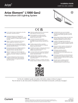
SKU Part Number Description Weight
System Input
Current (A)
IEC 62471
Risk Group
93150990 GEHI-HPPR-8S7N-1 LV Integral PPR, HE 8 foot, GL-LV, Non-dim 2.5 Kg
(5.5 lbs)
120/208/277VAC,
0.85/0.49/0.39A RG1
93151001 GEHI-HPPR-8S8N-1 HV Integral PPR, HE 8 foot, GL-HV, Non-dim 2.5 Kg
(5.5 lbs)
277/347/480VAC,
0.36/0.28/0.20A RG1
SKU Part Number Description
93151002 GECA60E14-OR22B Integral Leader cable 6.5 m/21.3 ft, UL
93151003 GECA60E14-GR08B Integral Jumper cable 2.4 m/7.87 ft
93151004 GECA60E14-GR02B Integral Jumper cable 0.6 m/1.96 ft
93151005 GECA60E14-GS02B Integral Y-splitter cable 0.6 m/1.96 ft
93151006 GECA60E14-DR06B Integral Jumper cable 1.8 m/5.9 ft, Wieland to LLT (Wieland is 3 pin)
93151008 GECA60FNA-NT00B Cap for female connector
93152175 GECA60C14-8R06B Leader cable, 6 ft, M25 to Nema L8-20P, UL
93152176 GECA60C14-7R06B Leader cable, 6 ft, M25 to Nema L7-15P, NA
93152177 GECA60C14-5R06B Leader cable, 6 ft, M25 to Nema 5-15P, NA
SKU Part Number Description
93151009 GEMB-CBH3 Suspension cable, 6.7 m/22 ft, adjustable end loop
93151010 GEMB-WAT3 Hook, wire form, 138 mm/5.43"
93151011 GEMB-WAT4 Hook, wire form, 238 mm/9.37"
93151012 GEMB-WAT5 Bracket, wire form, 58 mm/2.2 in diameter
Integral
Leader cable with connector cap (accessory)
Bracket (2X)
Hook (2X) (accessory)
Suspension cable (2X) (accessory)
Paper ruler (fold carton using the outlines to create a
triangle, then fold the tips into the designated holes)
Interconnection Cable Specications
Light Module Specications
Mounting Accessories Specications
Typical Kit Components
1
1
6
2
2
3
3
4
4
5
6
5
CAUTION / ATTENTION
Installation instructions and specications for accessories can be
found in the accessory package.
Les instructions d'installation et spécications pour les accessoires se
retrouvent dans le kit d'accessoires.

Arize® Integral Installation Guide
3
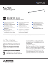
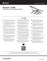
Sample Base Installation Diagram
Wiring Diagrams
> 65 cm (25.6")
from top crop leaf
Structural
members
40 cm (15.74")
50 cm (19.68")
60 cm (23.62")
between modules
Single-layer Installation Double-layer Installation
> 40 cm (15.7")
from lowest crop leaf
Optimal area to apply
the Arize Integral
The Integral should be
mounted 1 meter (39.3")
below the ceiling or away
from the wall.
3-Phase ∆
Black
Black
Black
White
White
White
Fixture
A1 Fixture
B1 Fixture
C1
* * *
Fixture
A1
N G
3-Phase Y
L3 L3
L2 L2
L1 L1
Black
Black
Black
White
White
White
Fixture
B1 Fixture
C1
Fixture
A2 Fixture
A2
Fixture
B2 Fixture
B2
Fixture
C2 Fixture
C2
Fixture
AN Fixture
AN
Fixture
BN Fixture
BN
Fixture
CN Fixture
CN

Arize® Integral Installation Guide
4
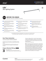
Put bracket on Inegral and push to lock. Slide brackets to end cap.
Wrap loop end of cable over
structural member, insert
gripper end through loop
end.
Attach hooks to suspension
cables. Adjust the height of
gripper end to make sure the
Integral is horizontal after
installation.
Hang Integral on suspension
cables with male connector
facing leader power cable.
Leader power cable
Male connector
Use paper ruler gauge to
ensure uniform spacing
between suspension cables.
Check orientation.
Attach a hook to each end
bracket.
Repeat steps 3-5 for remaining
Integrals. Connect modules
together with jumper cable and
ensure the male and female
connectors are snapped together
correctly.
CAUTION: Do not exceed the
maximum run length specied in
the Maximum Loading table (left).
SNAP!
Install Integral Bracket
One-layer Installation to the Mounting Unistrut
93.3 in.
(2.37 m)
93.3 in.
(2.37 m)
Paper ruler
CLICK!
Maximum Loading of Integral
Model Voltage (V) Current (A) Maximum Run Length (pcs)
GEHI-HPPR-8S7N-1 LV
120 0.85 11
208 0.49 19
240 0.43 23
277 0.39 26
GEHI-HPPR-8S8N-1 HV
277 0.36 26
347 0.28 33
480 0.20 46
12
1
4 5
2
3
3
6

Arize® Integral Installation Guide
5
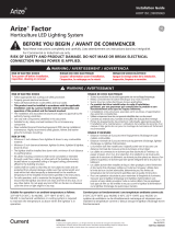
NOTE: To disassemble connectors,
rotate blue ring and pull to separate
connectors.
NOTE: Relieve the stress from the cable
connections by introducing a loop and
using cable ties. The lowest point of the
power cable should be just below the
lowest point of the male connector.
Electrical Connections
Connect AC Input Leader Cable to Integral
Rotate and remove the
connector cap from the
leader cable.
Recommended: secure AC
input leader cable.
Align keying features of
the male connector on the
1st Integral with female
connector on leader cable.
Put connector cap on the
female connector of the last
Integral in each chain. Rotate
the cap and make sure the
cap is installed to female
connector to comply to IP66.
Push connectors together
until a click is heard.
CLICK!
Align keying features
1
4
2
5
3
WARNING / AVERTISSEMENT
RISK OF ELECTRIC SHOCK OR PRODUCT DAMAGE
Turn power OFF before inspection, installation or removal.
RISQUE DE CHOC ÉLECTRIQUE OU DE DOMMAGE AU PRODUIT
Coupez l’alimentation avant l’inspection, l’installation ou la désinstallation.

Arize® Integral Installation Guide
6
Connect the black wire to Line 1
and white wires to Neutral or
Line 2 of the incoming AC line
either within a suitable junction
box or raceway provided with
a suitable strain relief; or by
means of a suitably rated plug
to a receptacle.
AC line
To driver input
Leader Cable with
Open Wire
Leader Cable with
NEMA Plug
Leader Cable with
Wieland Connector
Connecting to AC Line
Install the left and right Integral line with their own suspension cables and separate power cables. The horizontal
distance between the rst suspension cables of both Integral lines must be 180 mm. Follow all previous applicable
steps to build and complete both Integral lines.
Conguration When a Central Power Supply is Used
7 in.
(180 mm)
M25 Female
SOW
14AWG*2
NEMA
Plug 5-15P L7-15P L8-20P
NEMA
Receptacle 5-15R L7-15R L8-20R
M25 Female
AC Line
SOW
14AWG*2
Wieland Male
Wieland Female

Arize® Integral Installation Guide
This device complies with part 15 of the FCC Rules. Operation is subject to the following two conditions: (1) This device may not cause harmful interference,
and (2) this device must accept any interference received, including interference that may cause undesired operation.
NOTE: This equipment has been tested and found to comply with the limits for a Class A digital device, pursuant to part 15 of the FCC Rules. These limits
are designed to provide reasonable protection against harmful interference when the equipment is operated in a commercial environment. This equipment
generates, uses, and can radiate radio frequency energy and, if not installed and used in accordance with the instruction manual, may cause harmful
interference to radio communications. Operation of this equipment in a residential area is likely to cause harmful interference in which case the user will be
required to correct the interference at his own expense.
This Class [A] RFLD complies with the Canadian standard ICES-005. /CeDEFR de la classe [A] est conforme à la NMB-005 du Canada.
Horticultural lighting. Not suitable for household illumination.
Save These Instructions
Use only in the manner intended by the manufacturer. If you have any questions, contact the manufacturer.
Electrical products must not be thrown out with domestic waste. They must be taken to a communal collecting point for environmentally friendly disposal
in accordance with local regulations. Contact your local authorities or stockist for advice on recycling. The packaging material is recyclable. Dispose of the
packaging in an environmentally friendly manner and make it available for the recyclable material collection-service.
When mounting a second Integral line below the rst line, attach hooks to the bottom of the upper line bracket
and the top of the lower line bracket. The vertical center to center distance between lines may be customized by
choosing dierent combinations of mounting hooks. Follow all previous applicable steps to build and complete
second Integral line. NOTE: No more than two lines of Integrals may be suspended from a suspension cable.
Two-layer Installation
Use dierent combinations
of mounting hooks to
produce desired vertical
distance between Integrals
(see table below)
Hook
Hook
Hook Option 1 Hook Option 2 Distance between Integral
lines (center to center)
Hook 1 (138 mm/5.43") Hook 1 (138 mm/5.43") 400 mm (15.74")
Hook 1 (138 mm/5.43") Hook 2 (238 mm/9.37") 500 mm (19.68")
Hook 2 (238 mm/9.37") Hook 2 (238 mm/9.37") 600 mm (23.62")
IP66
gecurrent.com/arize
© 2022 Current Lighting Solutions, LLC. All rights reserved. Information and specications subject to change
without notice. All values are design or typical values when measured under laboratory conditions.
Page 7 of 7
(Rev 11/09/22)
HORT166 | DOC-2001858
1/7